For 1990-2009 cars only
Special Tools
J-42188-B Ball Joint Separator
Removal Procedure
- Raise and support the vehicle. Refer to Lifting and Jacking the Vehicle.
- Remove the tire and wheel assembly. Refer to Tire and Wheel Removal and Installation.
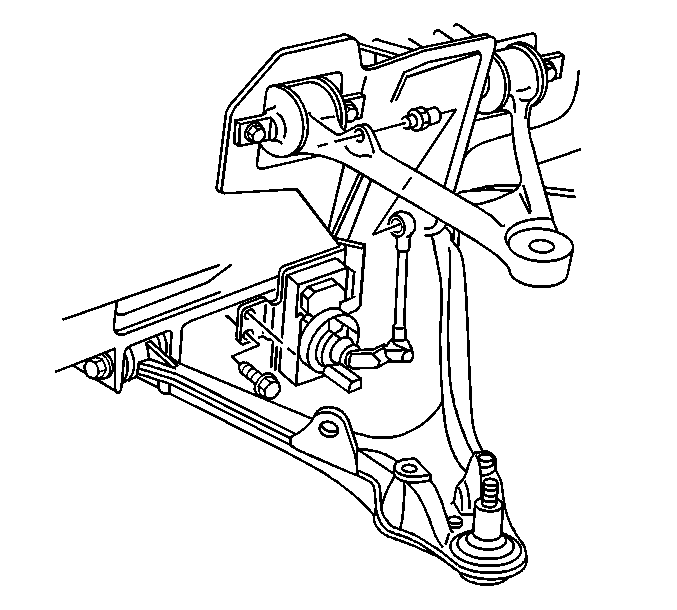
- Disconnect the electronic suspension control (ESC) sensor link.
- Support the lower control arm with a jackstand.
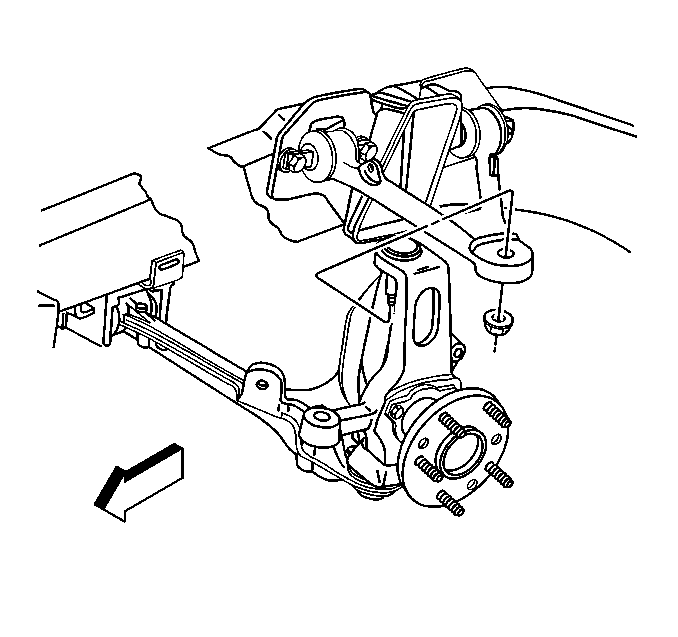
- Loosen the ball joint stud nut but do not remove the nut.
- Using tool J-42188-B separate the upper ball joint stud from the upper control arm.
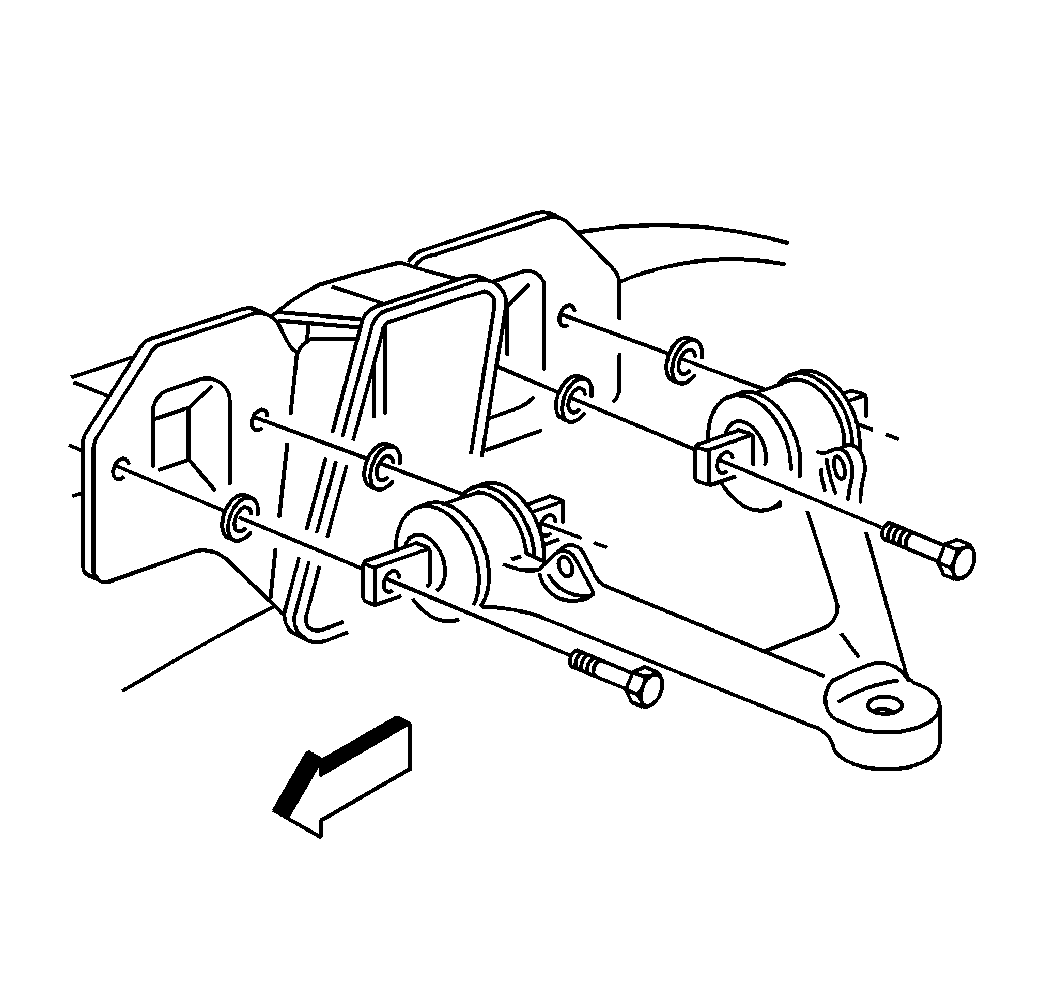
- Remove the upper control arm bolts and shims. Note the number and position of the shims for installation purposes.
- Remove the upper control arm from the vehicle.


Note: The upper control arm shims will have an effect on the camber and the caster. Make sure to use an equal thickness of shims on both sides of each individual upper control arm bushing.
Installation Procedure
- Install the upper control arm to the vehicle.
- Install the upper control arm shims.
- Install the upper control arm mounting bolts to the upper control arm and frame rail.
- Install the upper ball joint stud into the upper control arm. It will be necessary to use an allen wrench to keep the ball joint stud from spinning while tightening the ball joint stud nut.
- Connect the ESC sensor link.
- Remove the jackstand.
- Install the tire and wheel assembly. Refer to Tire and Wheel Removal and Installation.
- Lower the vehicle.

Note: The upper control arm shims will have an effect on the camber and the caster. Make sure to use an equal thickness of shims on both sides of each individual upper control arm bushing.
Caution: Refer to Fastener Caution in the Preface section.
Tighten
Tighten the upper control arm mounting bolts to 65 N·m (48 lb ft).

Tighten
Tighten the upper control arm ball joint stud nut to 20 N·m (15 lb ft) plus 250 degrees.

