Special Tools
| • | DT-47596 Bearing Cup Remover |
| • | J 25070 Heat Gun -- 500-750F |
| • | J 41623-B Cooler Quick Connect Tool |
| • | J 42155 Getrag Axle Differential Housing Lifting Tool |
| • | J 42173 Getrag Axle Ring Gear Holder |
| • | J-42173-10 Fixture Modification Template |
For equivalent regional tools, refer to
Special Tools.
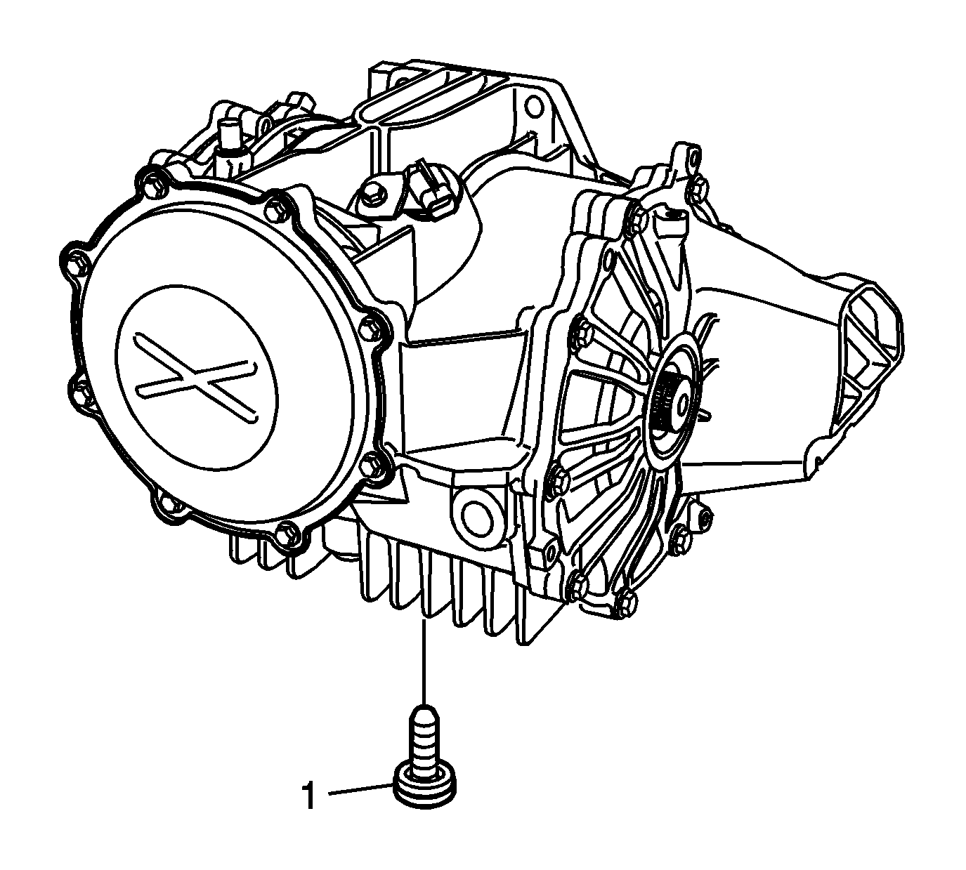
- Remove the drain plug and washer (1) and allow the fluid to drain.
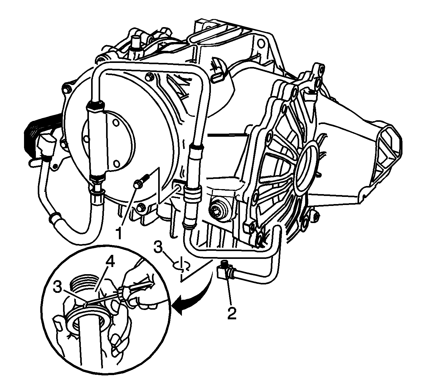
- To drain the fluid from models equipped with a pump and cooler, perform the following steps:
| 2.1. | Remove the bolt (1) retaining the lower inlet pipe clamp. |
| 2.2. | Using a bent tip screwdriver, remove the quick connect fitting retaining ring (3) from the quick connect fitting (4), and discard the retaining ring. |
| 2.3. | Drain the fluid by pulling the lower inlet pipe (2) straight out of the quick connect fitting. |
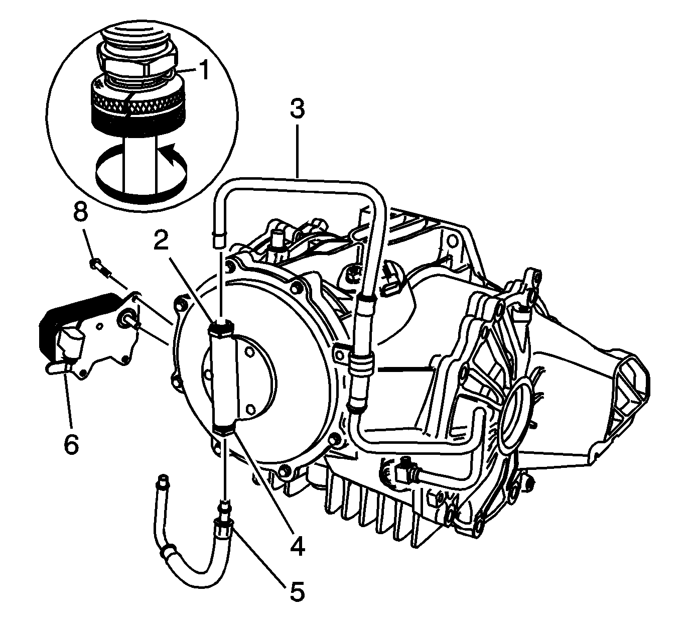
- For models equipped with a pump and cooler, perform the following steps to remove the cooler and pipes:
| 3.1. | Using the
J 41623-B cooler tool
, remove the inlet and outlet pipes by aligning notches on the
J 41623-B cooler
tool
with quick connect fittings (2, 4, 6) and rotating the tool to release pipes (3 and 5) from the quick connect fittings. |
| 3.2. | Remove the 3 cooler retaining bolts (8). |
| 3.3. | Remove the cooler (7). |
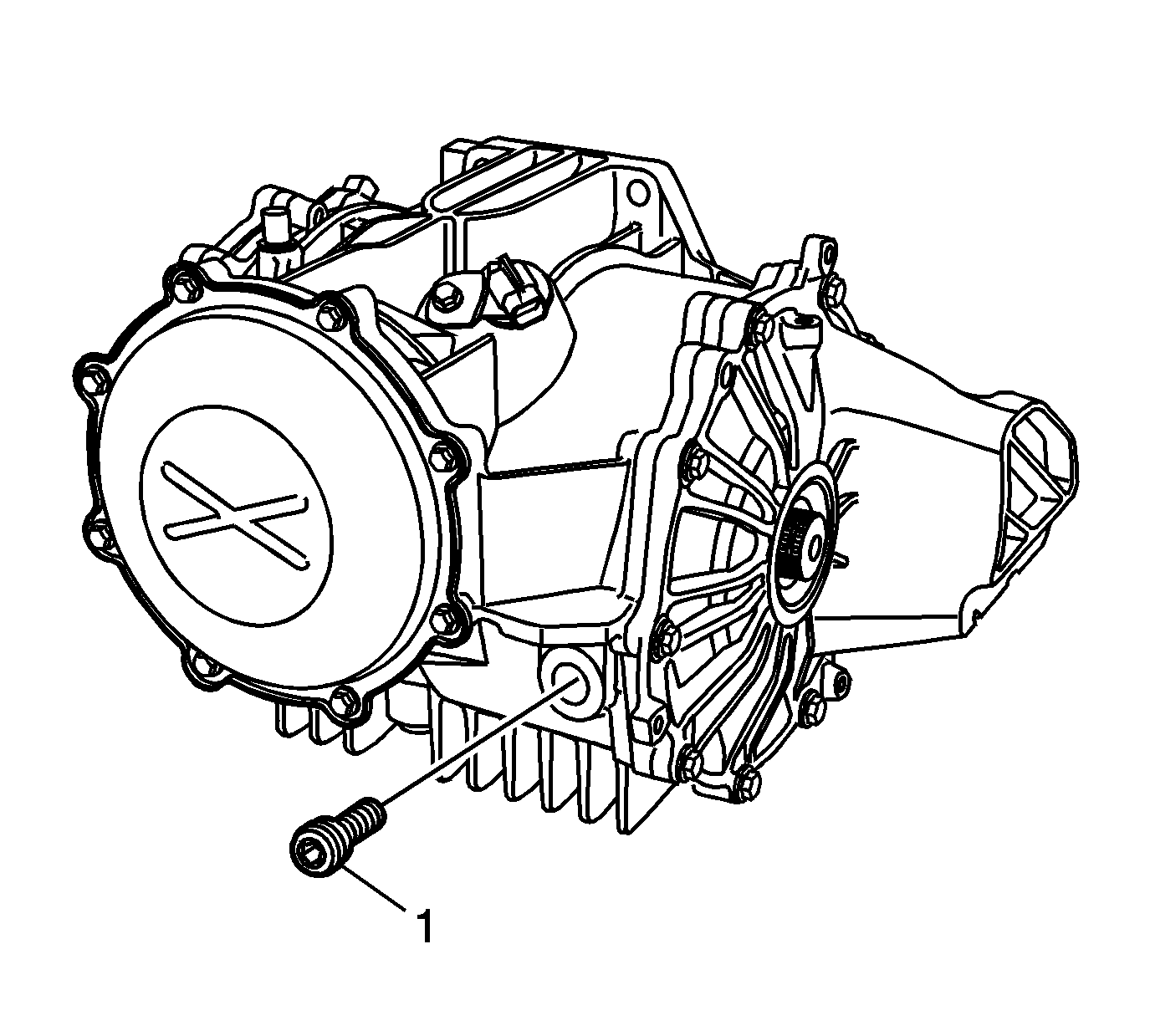
- Remove the fill plug and washer (1).
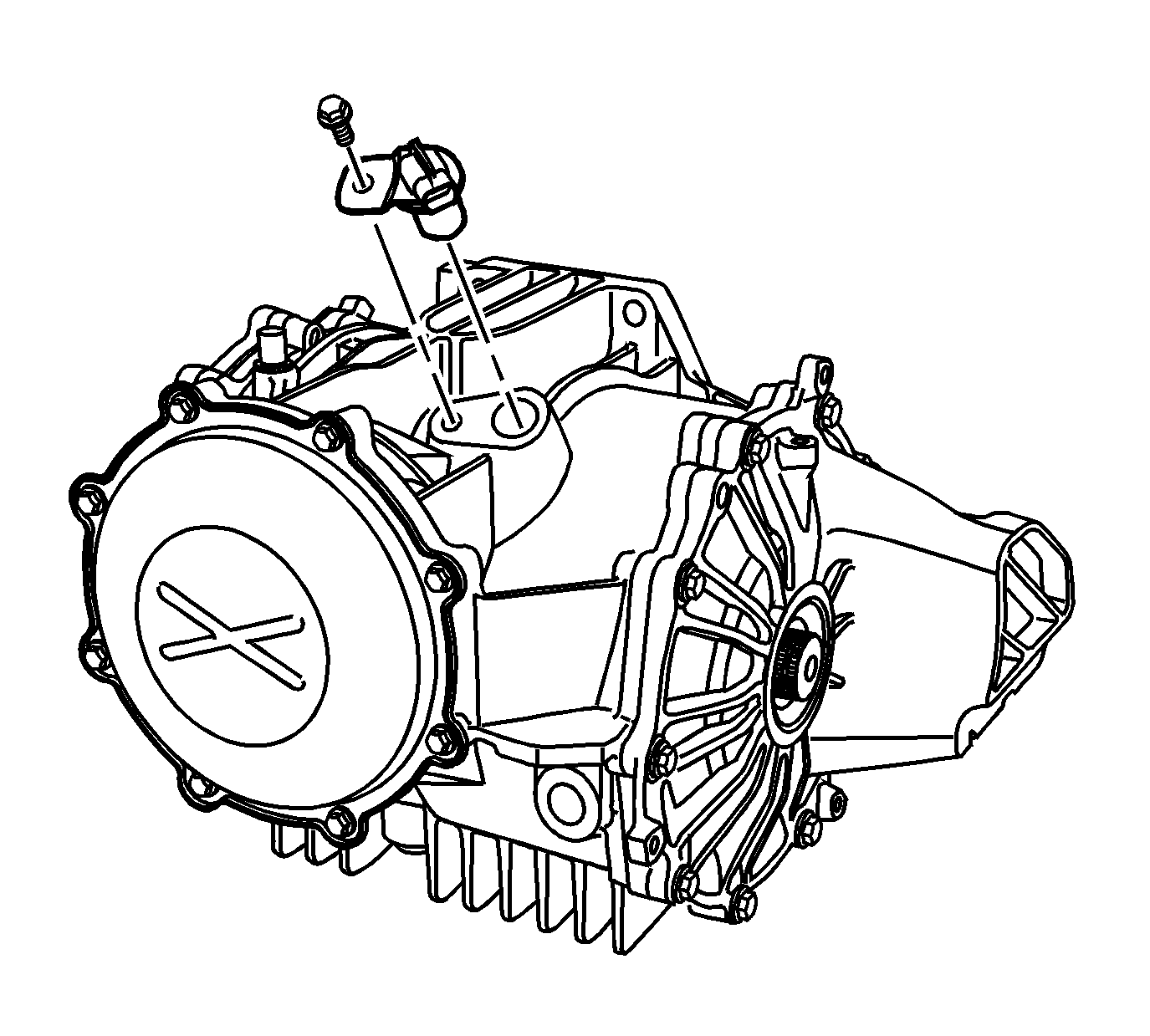
- Remove the vehicle speed sensor and bolt, if equipped.
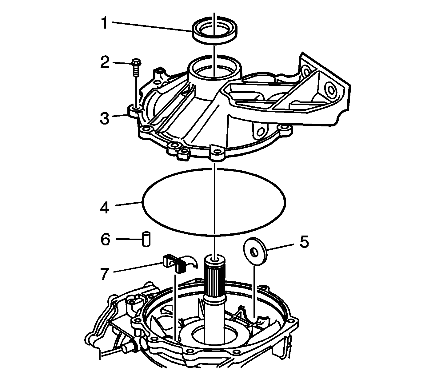
- Remove the left cover (3) and bolts (2).
- Remove the O-ring (4) and oil seal (1) from the cover.
- Remove the magnet (5) and dowel (6) from the carrier.
- Remove the oil trough (7).
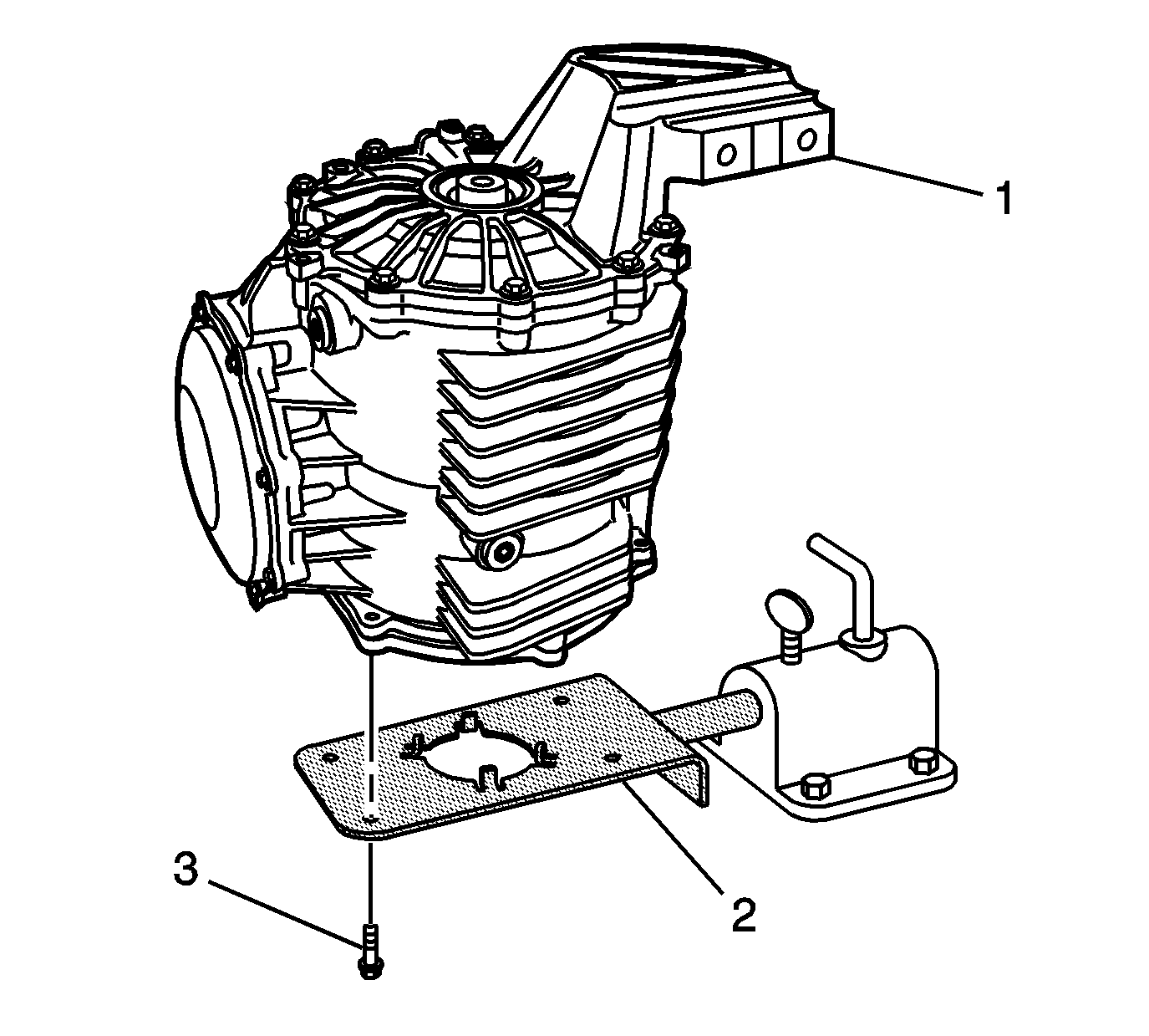
- Install the differential assembly (1) onto the
J 42173 ring gear holder
(2).
Caution: Refer to Fastener Caution in the Preface section.
- Install 4 M8 x 1.25 bolts (3). Tighten the bolts to
30 N·m (22 lb ft).
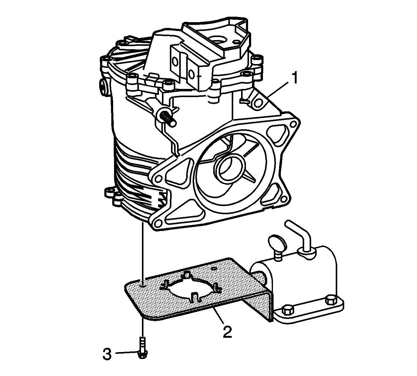
Note: Z06 models require the modification of
J 42173 ring gear holder
, using
J-42173-10 template
.
- Install the differential assembly (1) onto the
J 42173 ring gear holder
(2).
- Install 2 M8 x 1.25 bolts (3). Tighten the bolts to
30 N·m (22 lb ft).
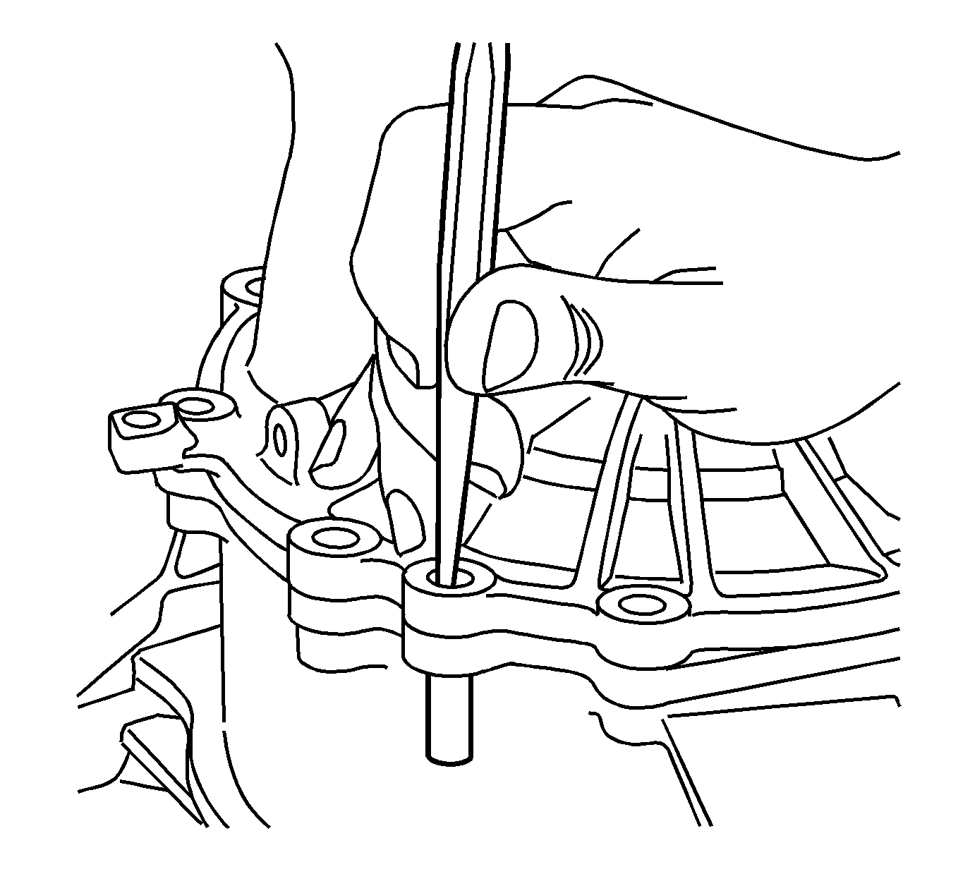
- Using a punch, remove the cover alignment pin.
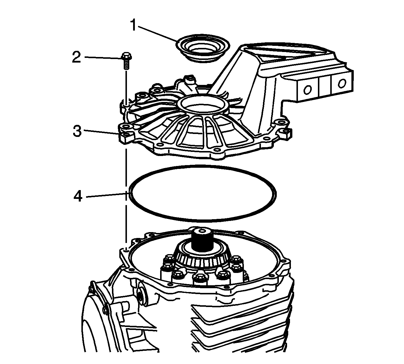
- Remove the right cover (3) and bolts (2) from the differential.
- Remove the O-ring (4) and oil seal (1) from the cover.
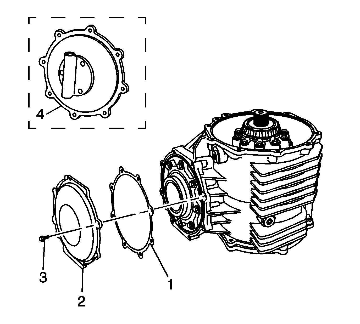
- Remove the rear cover (2), bolts (3), and gasket (1), or pump - some models (4).
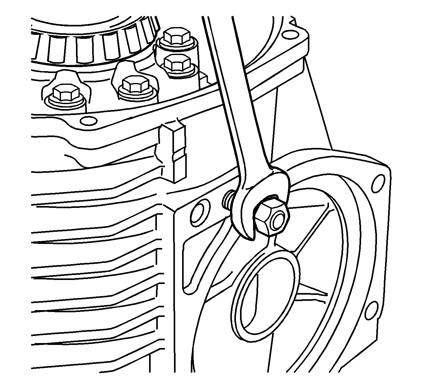
- Install 2 M10 x 1.5 nuts onto the transmission stud. Remove the stud from the differential, if equipped.
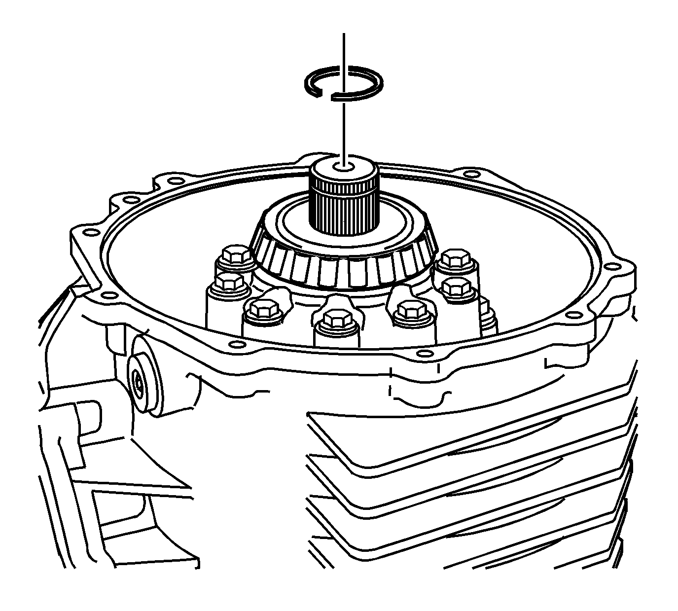
- Remove the C-clip from the output shaft.
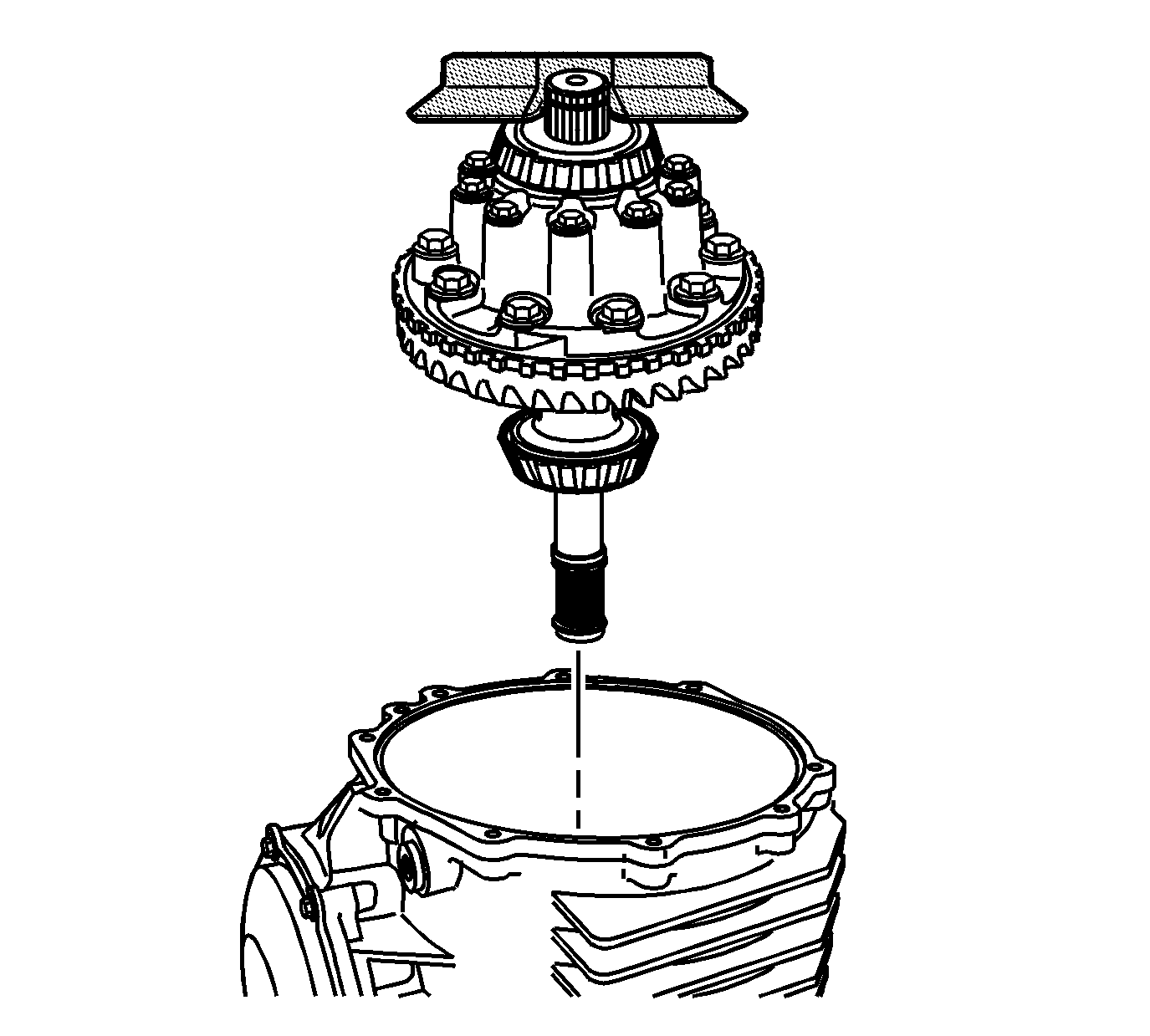
- Install the
J 42155 lifting tool
into the groove of the output shaft in order to remove the differential case assembly.
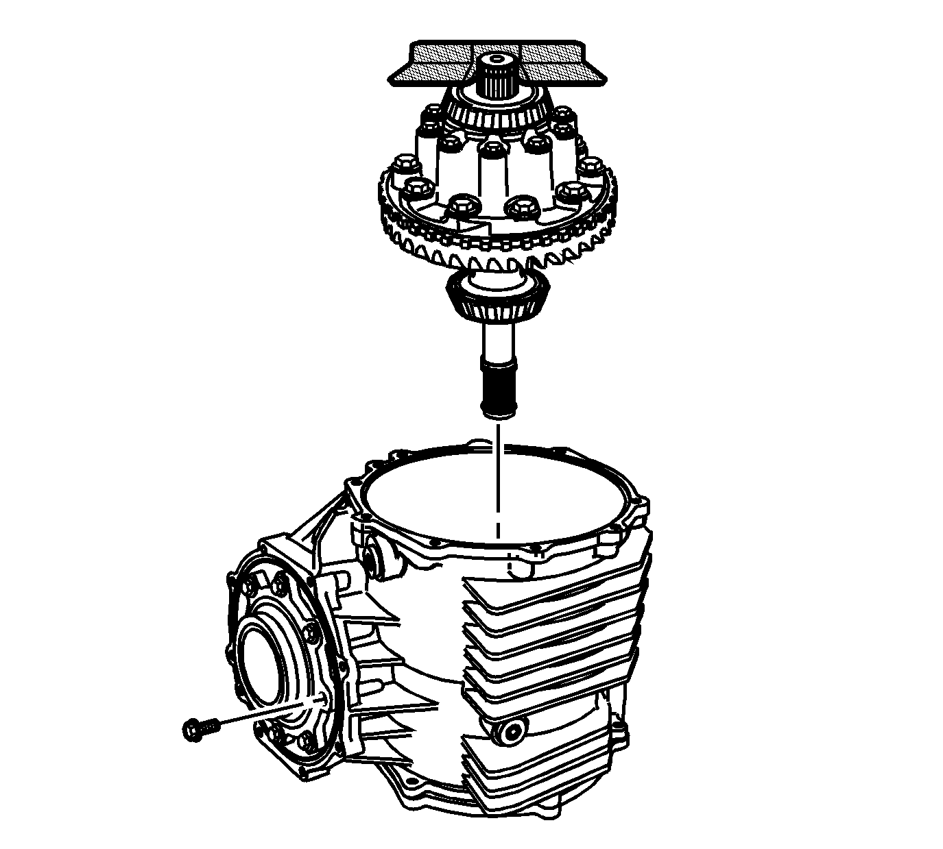
- Remove the pinion housing/cage bolts.
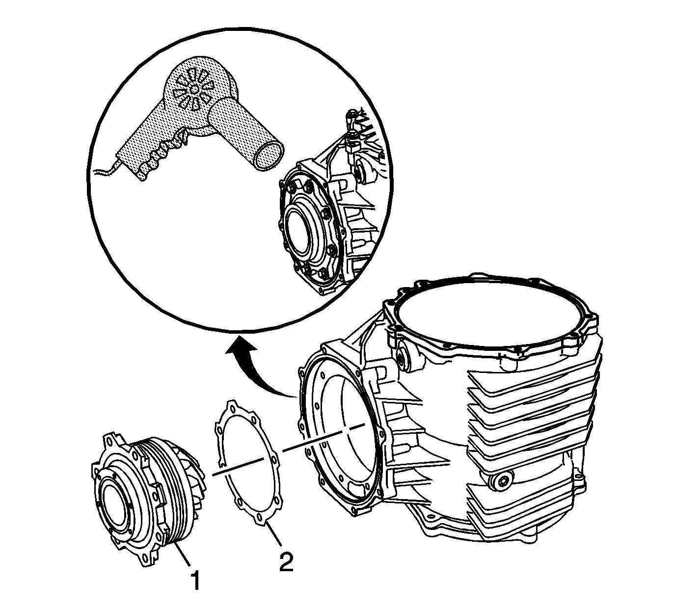
- Using the
J 25070 heat gun
, heat the differential housing around the pinion housing. Heating the housing will ease in pinion removal.
- Remove the pinion housing/cage assembly (1) and shims (2) from the differential housing. Mark or tag the shims for assembly.
Locate 2 screwdrivers or pry bars to the flange area of the pinion housing/cage to ease
in removal.
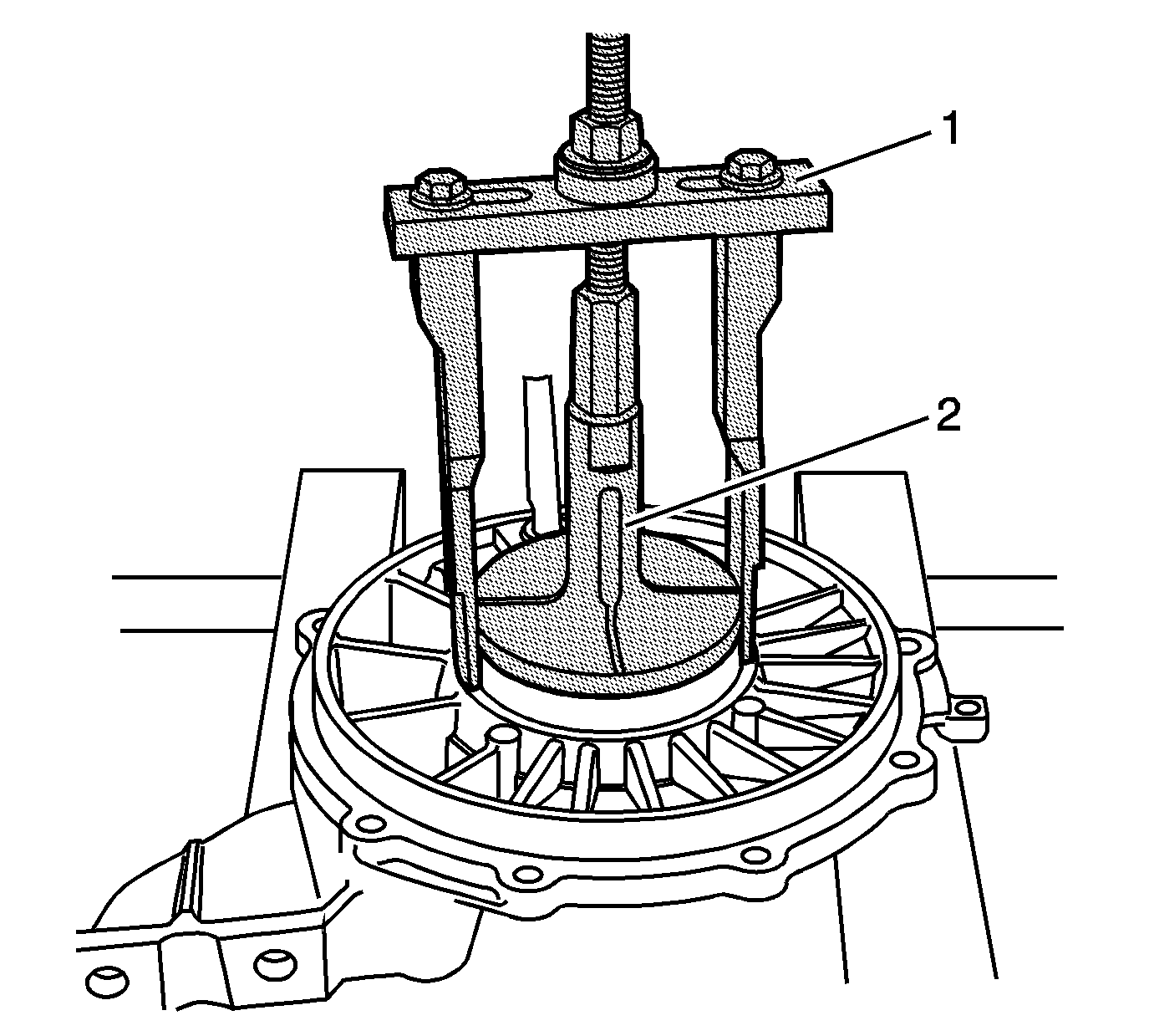
- Install the
DT-47596 bearing remover
(2) into the right cover. Tighten securely into the bearing cup.
- Place
J 45124 removal bridge
(1) over
DT-47596 bearing remover
(2). Adjust legs for
best fit. Install supplied bolt, nut, thrust bearing and washer. Hold the bolt and tighten the nut to remove the bearing cup and shim.
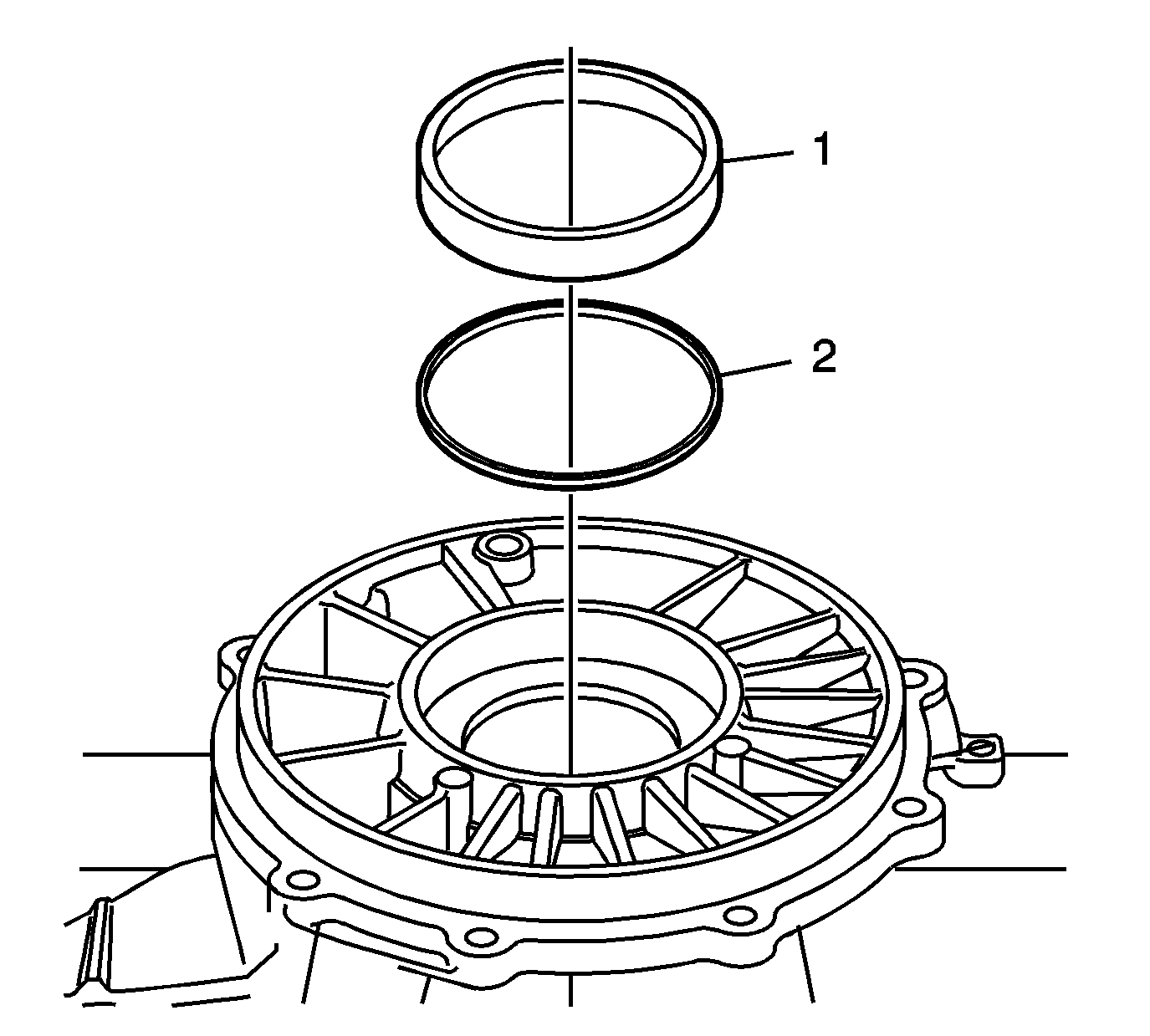
- Remove the bearing cup (1) and shim (2). Mark or tag the shims for assembly.
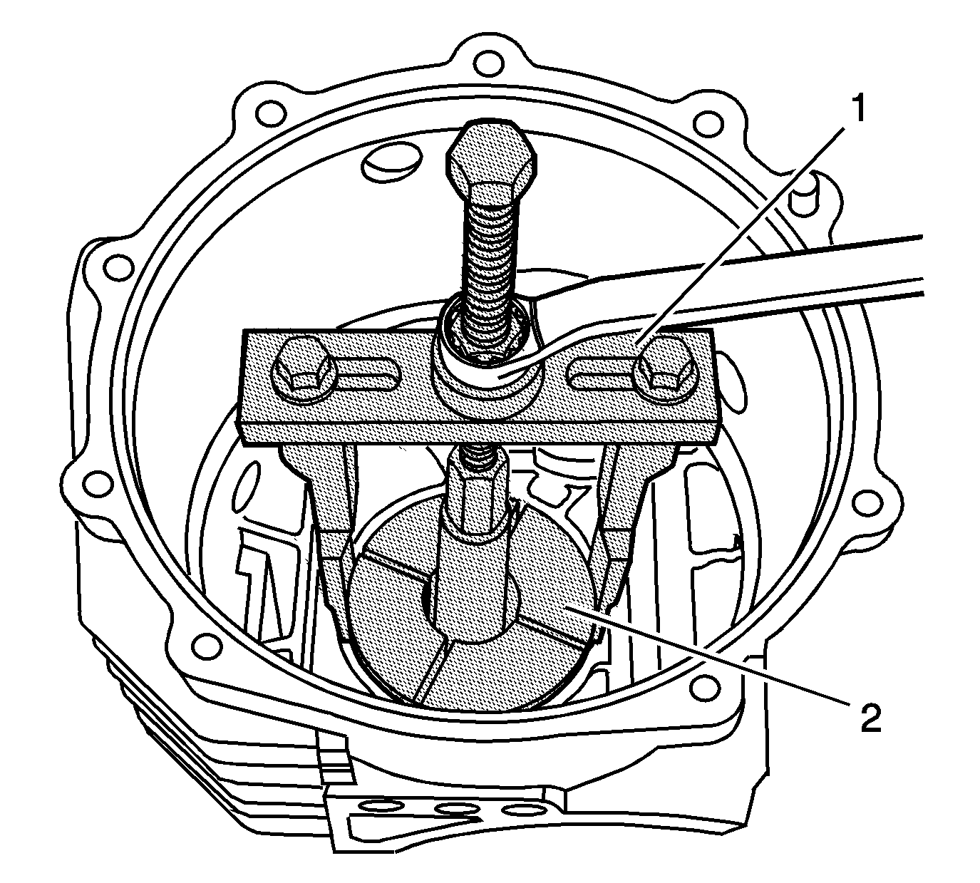
- Install the
DT-47596 bearing remover
(2) into the differential housing, behind the left bearing cup. Tighten securely into the bearing cup.
- Place
J 45124 removal bridge
(1) over
DT-47596 bearing remover
(2). Adjust legs for
best fit. Install supplied bolt, nut, thrust bearing and washer. Hold the bolt and tighten the nut to remove the bearing cup and shim.
- Remove the cup (2) and shim (1) from the differential housing. Mark or tag the shims for assembly.


