Drive Pinion Shim Selection Base
Special Tools
| • | J 42168-1 Shim Measuring Tool |
| • | J 42168-2 Shim Measuring Tool |
| • | J 42168-9 Shim Measuring Tool |
| • | J 42168-11 Shim Measuring Tool |
| • | J 42173 Getrag Axle Ring Gear Holder |
For equivalent regional tools, refer to Special Tools.
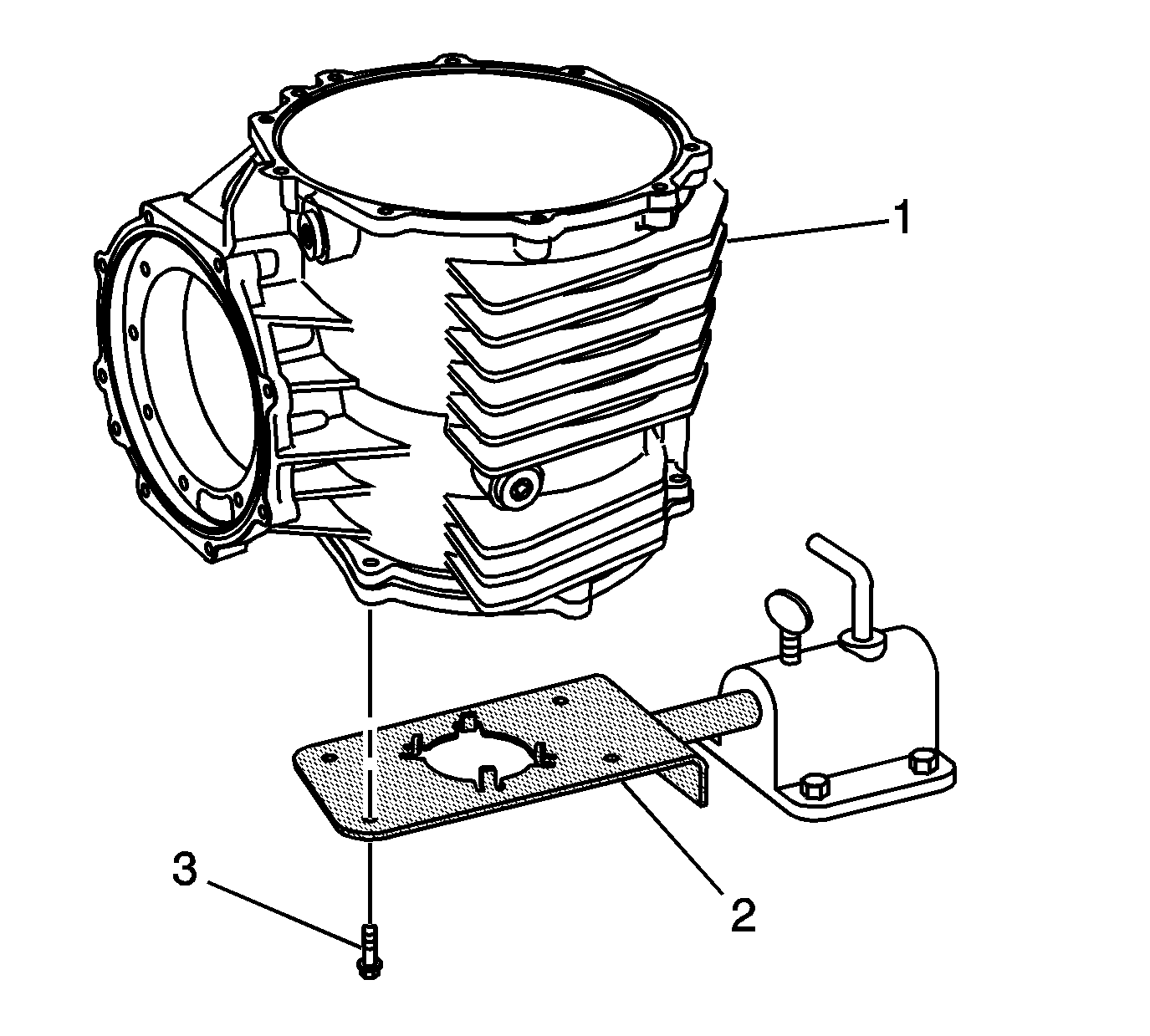
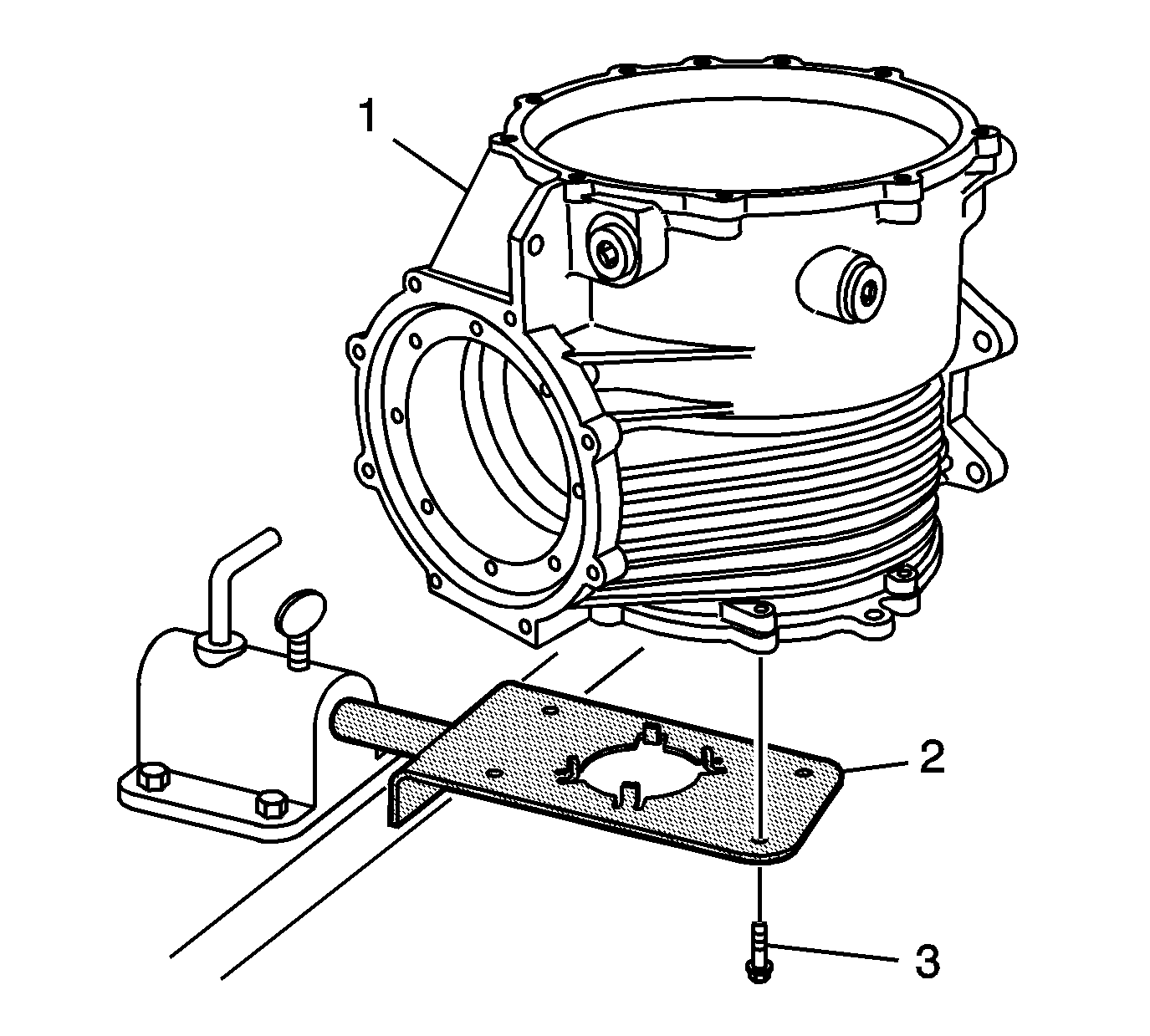
- Install the differential assembly (1) onto the J 42173 ring gear holder (2).
- Install 4 M8 x 1.25 bolts (3). Tighten the bolts to 30 N·m (22 lb ft).
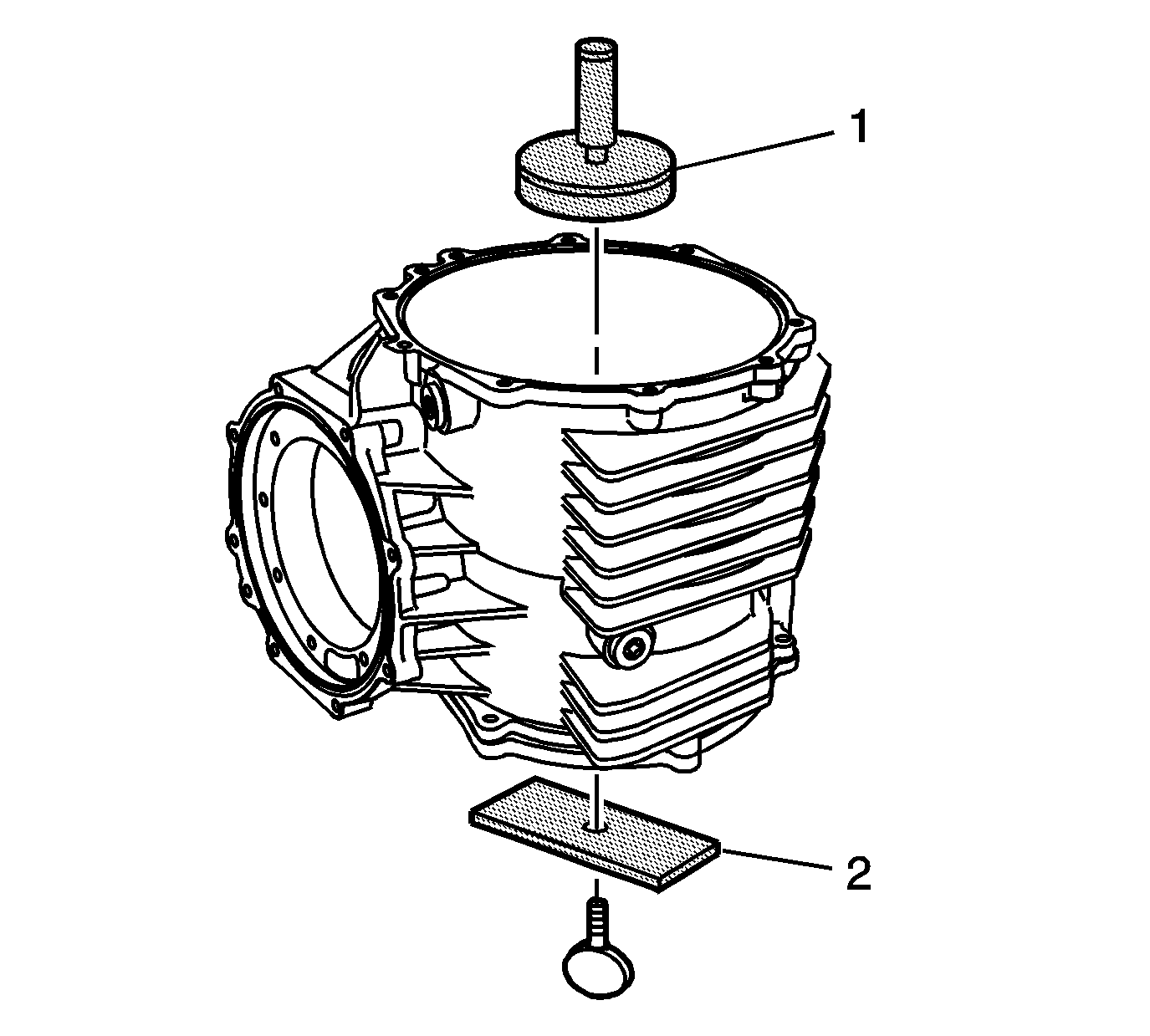
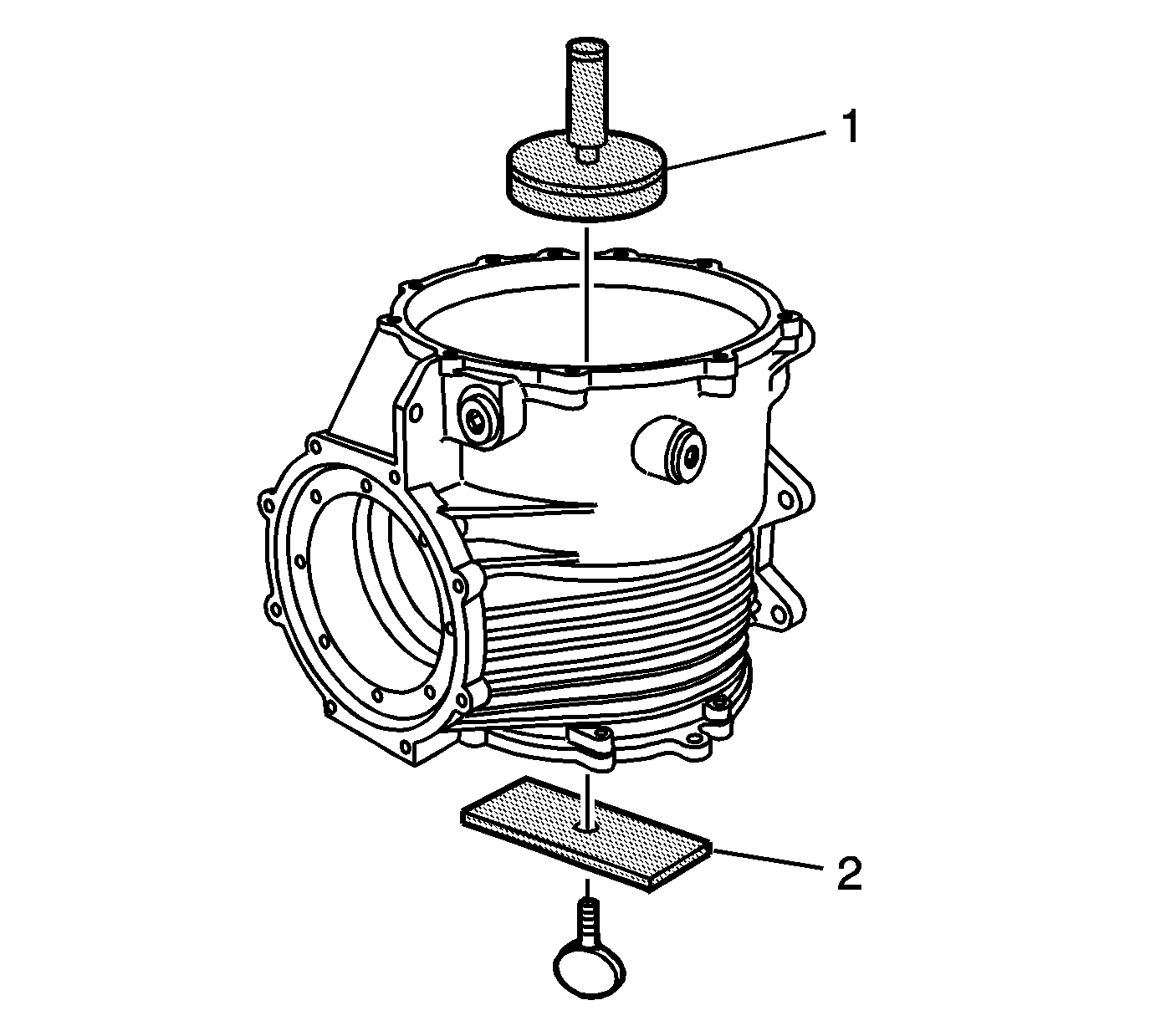
- Install the J 42168-1 measuring tool (1) into the left bearing cup bore of the differential housing.
- Install the J 42168-9 measuring tool (2) and thumbscrew to the J 42168-1 measuring tool (1). Tighten the thumbscrew until snug.
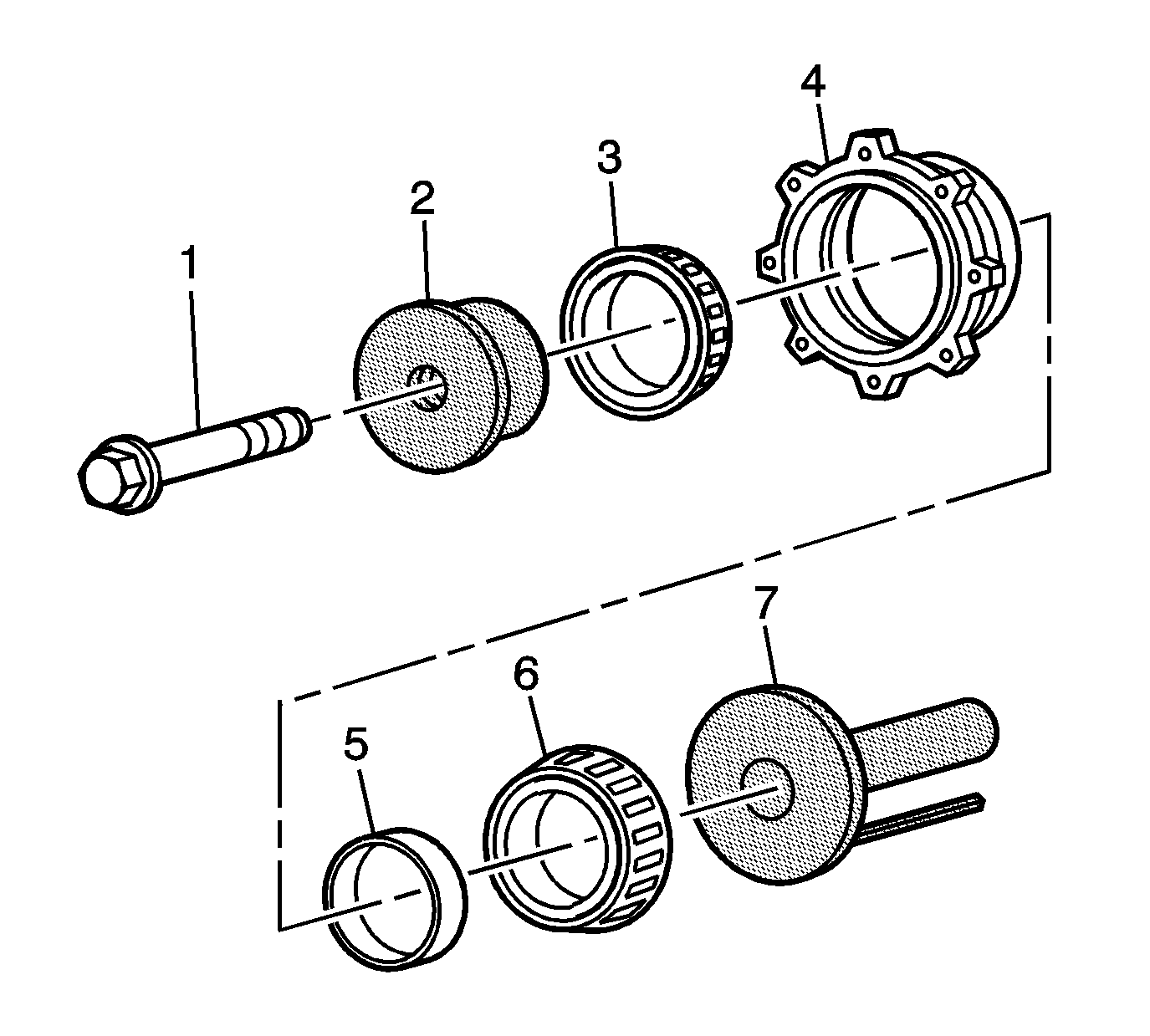
- Install the J 42168-11 measuring tool (2), bearings (3 and 6), spacer (5), J 42168-2 measuring tool (7), and bolt (1) to the pinion housing/cage (4). Tighten the bolt until snug.
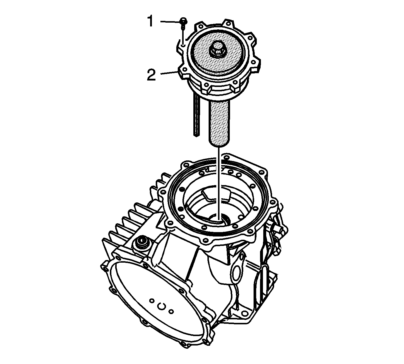
- Install the pinion housing/cage assembly (2) into the differential housing.
- Install the pinion housing/cage bolts (1). Tighten the bolts to 30 N·m (22 lb ft).
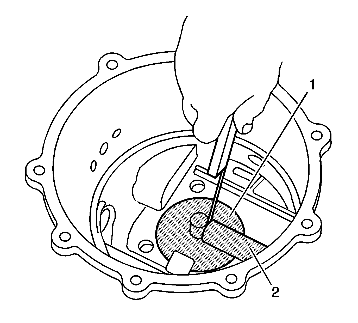
- Using a feeler gage, measure the distance between the J 42168-2 measuring tool (2) and the J 42168-1 measuring tool (1). Record the dimension as B1.
- Subtract the B1 value from a B nominal value of 5 mm (0.197 in). Record that calculation as B2.
- Locate the A1 value (1) on the side of the ring gear.
- Subtract the A nominal value of 103.00 mm (4.055 in) from the A1 value. Record the calculation as B3.
- Add the B2 value to the B3 value for the proper pinion housing shim thickness. The B3 value may be a positive, negative, or zero value.
- Select shims equal to the calculated value. It may be necessary to round the shim or shims total to obtain the proper size shim pack. If the shim thickness calculation is past the midpoint value, round the number higher to the next decimal value.
Note: The pinion depth adjustment procedure and shim selection must be performed prior to pinion shaft and housing assembly.
Caution: Refer to Fastener Caution in the Preface section.
The use of M8 x 1.25 dowels or long bolts will ease in pinion housing installation and alignment.
Note: ALL of the pinion housing/cage bolts must be installed in order to obtain an accurate measurement and correct shim selection.
Refer to the applicable calculation tables in Spacer and Shim Specifications.
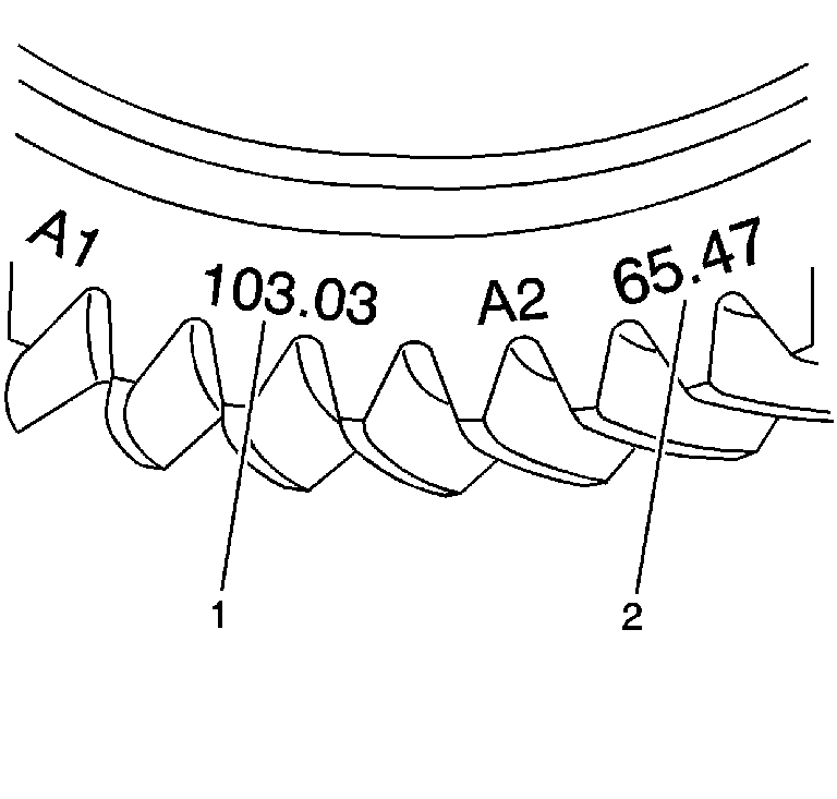
Note: The A1 value is a manufacturing variation between the ring gear and pinion. The A1 value may be higher, lower, or equal to 103.00 mm (4.055 in) nominal value. When subtracting the A nominal value from the A1 value, the B3 calculation may compute to a positive, negative, or zero total.
Refer to Rear Axle Specifications.
Drive Pinion Shim Selection Z06
Special Tools
| • | DT-48009 Shim Selection Adapters |
| • | J 42168-1 Shim Measuring Tool |
| • | J 42168-9 Shim Measuring Tool |
| • | J 42168-11 Shim Measuring Tool |
| • | J 42173 Getrag Axle Ring Gear Holder |
For equivalent regional tools, refer to Special Tools.
- Install the differential assembly (1) onto the J 42173 ring gear holder (2).
- Install 4 M8 x 1.25 bolts (3). Tighten the bolts to 30 N·m (22 lb ft).
- Install the J 42168-1 measuring tool (1) into the left bearing cup bore of the differential housing.
- Install the J 42168-9 measuring tool (2) and thumbscrew to the J 42168-1 measuring tool (1). Tighten the thumbscrew until snug.
- Install the J 42168-11 measuring tool (2), bearings (3 and 6), spacer (5), DT-48009 adapters (7), and bolt (1) to the pinion housing/cage (4). Tighten the bolt until snug.
- Install the pinion housing/cage assembly (2) into the differential housing.
- Install the pinion housing/cage bolts (1). Tighten the bolts to 30 N·m (22 lb ft).
- Using a feeler gage, measure the distance between the DT-48009 adapters (2) and the J 42168-1 measuring tool (1). Record the dimension as B1.
- Subtract the B1 value from a B nominal value of 3 mm (0.118 in). Record that calculation as B2.
- Locate the A1 value (1) on the side of the ring gear.
- Subtract the A nominal value of 103.00 mm (4.055 in) from the A1 value. Record the calculation as B3.
- Add the B2 value to the B3 value for the proper pinion housing shim thickness. The B3 value may be a positive, negative, or zero value.
- Select shims equal to the calculated value. It may be necessary to round the shim or shims total to obtain the proper size shim pack. If the shim thickness calculation is past the midpoint value, round the number higher to the next decimal value.
Note: The pinion depth adjustment procedure and shim selection must be performed prior to pinion shaft and housing assembly.
Caution: Refer to Fastener Caution in the Preface section.


The use of M8 x 1.25 dowels or long bolts will ease in pinion housing installation and alignment.
Note: ALL of the pinion housing/cage bolts must be installed in order to obtain an accurate measurement and correct shim selection.
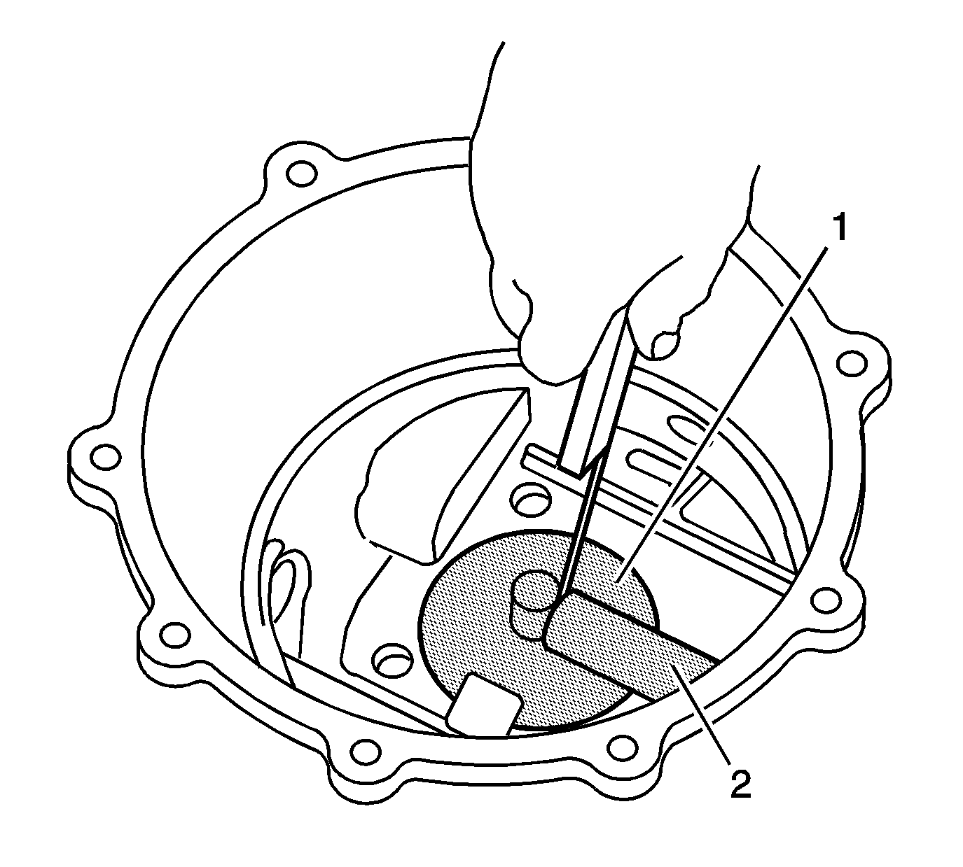
Refer to the applicable calculation tables in Spacer and Shim Specifications.
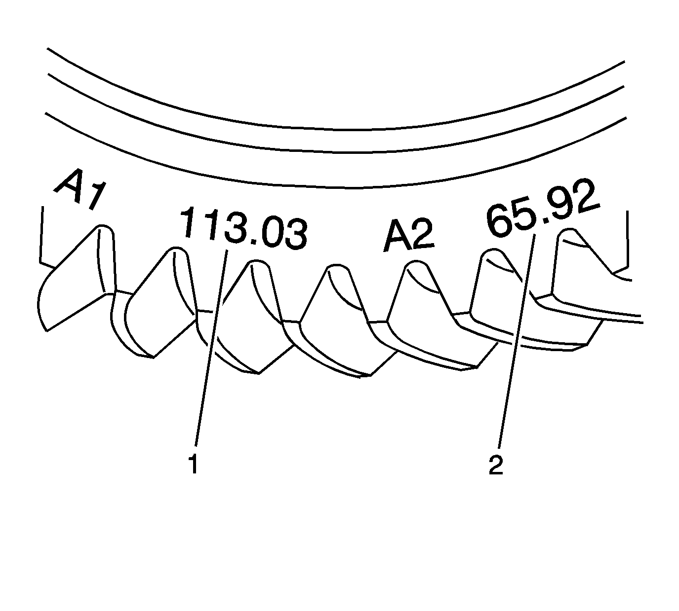
Note: The A1 value is a manufacturing variation between the ring gear and pinion. The A1 value may be higher, lower, or equal to 103.00 mm (4.055 in) nominal value. When subtracting the A nominal value from the A1 value, the B3 calculation may compute to a positive, negative, or zero total.
Refer to Rear Axle Specifications.
