Special Tools
| • | DT 48827 Skip Shift Socket
|
| • | J 3289-20 Holding Fixture
|
| • | J 6125-1B Slide Hammer with Adapter
|
| • | J 8433 Universal Bridge Puller
|
| • | J 39431 Gear Remover and Bolts
|
| • | J 44395-A Transmission Holding Fixture
|
Extension Housing Removal
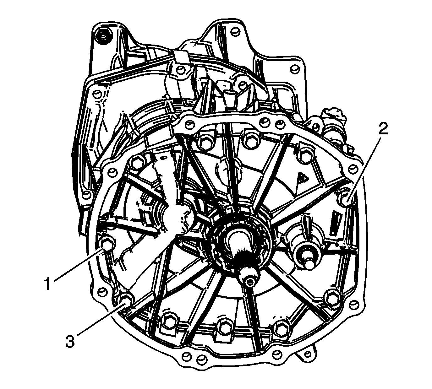
- Remove the adapter plate bolts (1, 2, and 3).
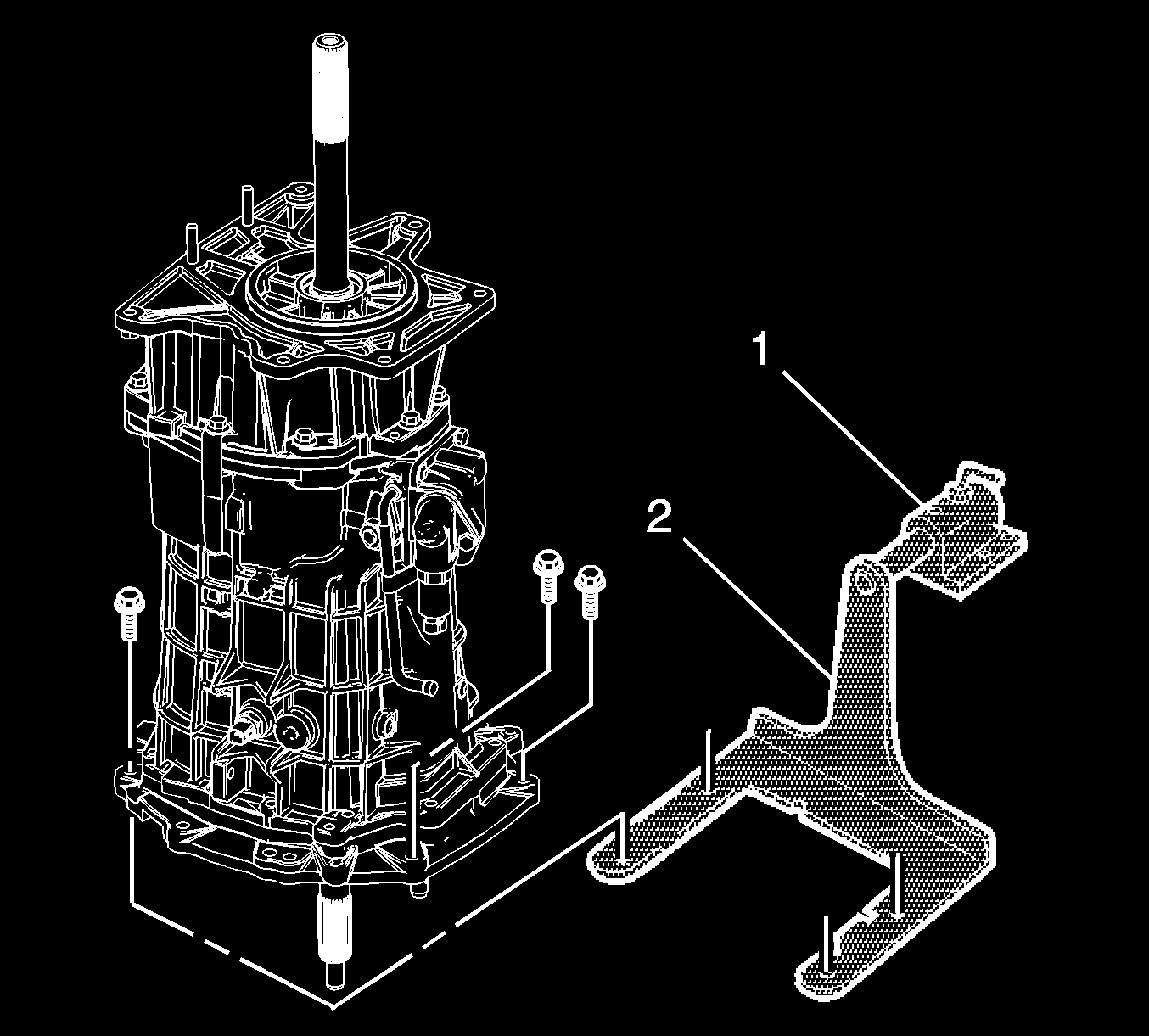
- Install the
J 44395-A holding fixture
(2).
- Mount the transmission on a workbench using the
J 3289-20 holding fixture
(1).
- Rotate the transmission into a horizontal position.
- Remove the transmission drain plug and drain the transmission fluid.
- Shift the transmission into neutral (N).
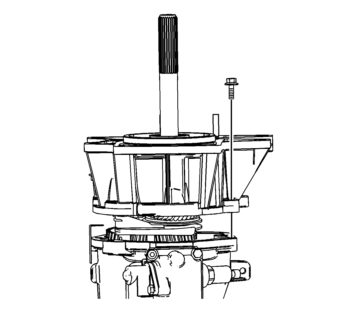
- Remove the rear extension housing bolts and the rear
extension housing.
Reverse Speed Gear Removal
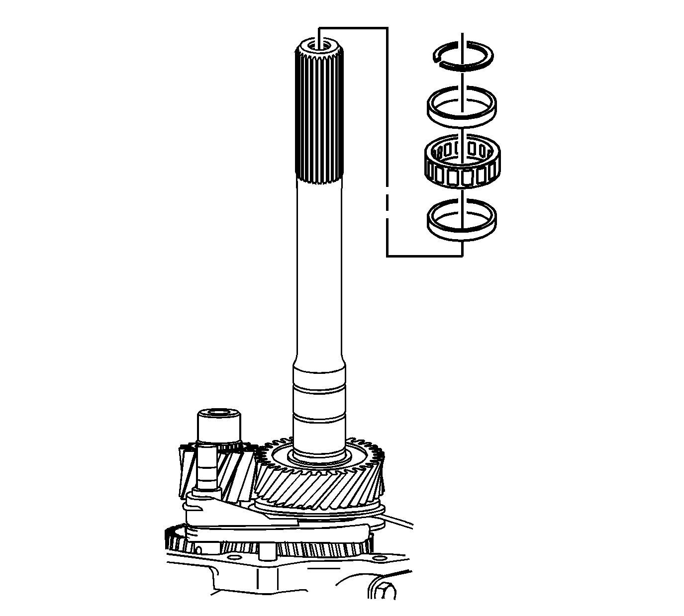
- Remove the rear bearing retainer ring.
- Remove the spacer.
- Remove the mainshaft rear roller bearing.
- Remove the spacer.
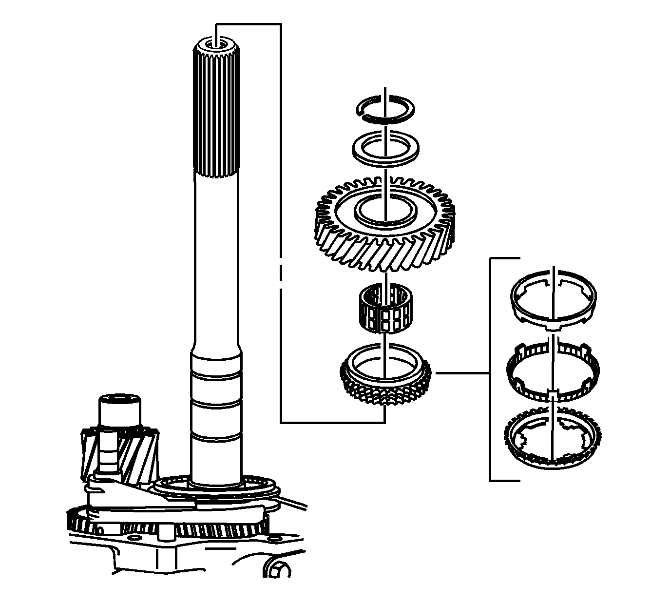
- Remove the retainer ring.
- Remove the reverse gear thrust washer.
- Remove the reverse gear.
- Remove the reverse gear caged needle bearing.
- Remove the reverse drive gear inner cone.
- Remove the reverse drive gear intermediate cone.
- Remove the reverse gear synchronizer blocking ring.
Reverse Shift Fork Removal
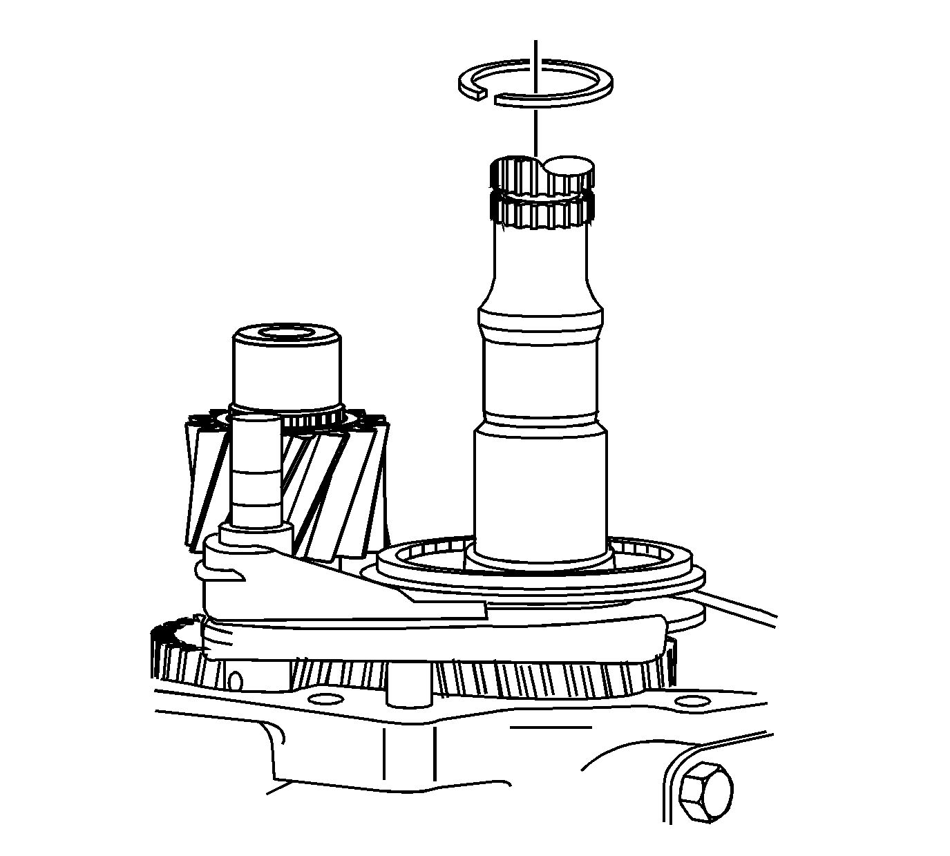
- Remove the reverse synchronizer retainer ring.
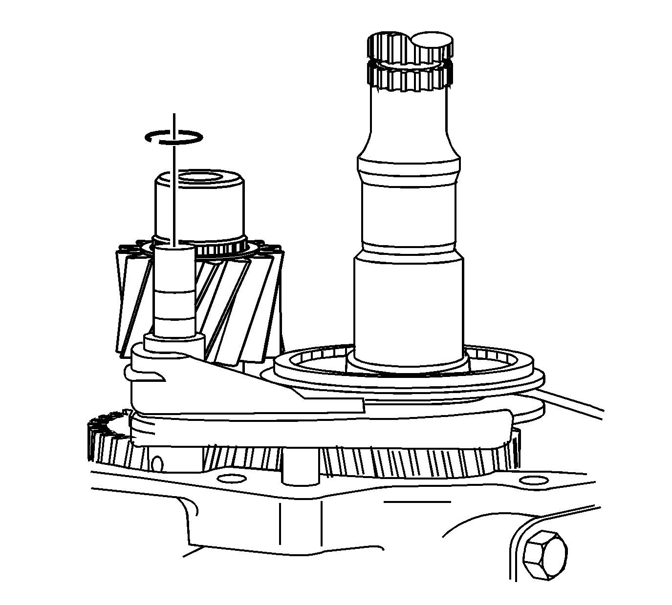
- Remove and discard the reverse shift fork retainer ring.
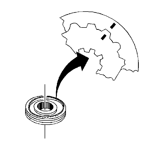
- Scribe a mark on the synchronizer hub and on the sleeve. This will help you to reinstall the parts in the same
position.
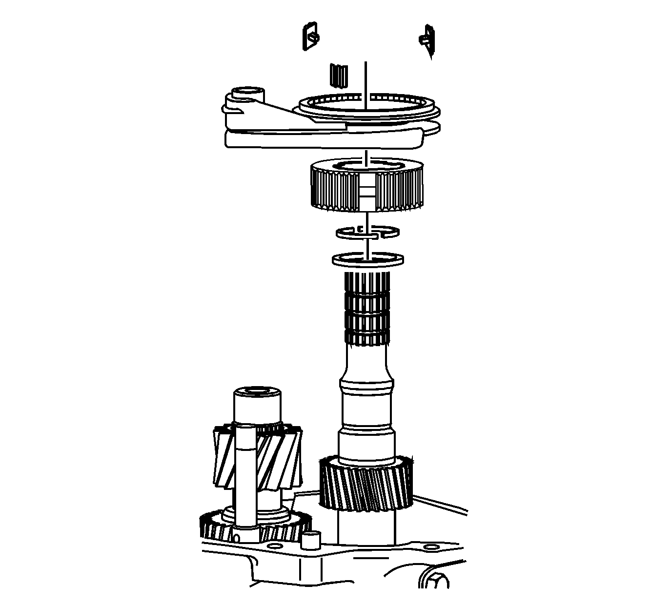
- Remove the following parts in order:
| 4.1. | The reverse synchronizer sleeve, shift fork, and inserts |
| 4.2. | Pry to remove the reverse synchronizer hub |
| 4.4. | The two piece thrust washer |
5th/6th Speed Driven Gear Removal
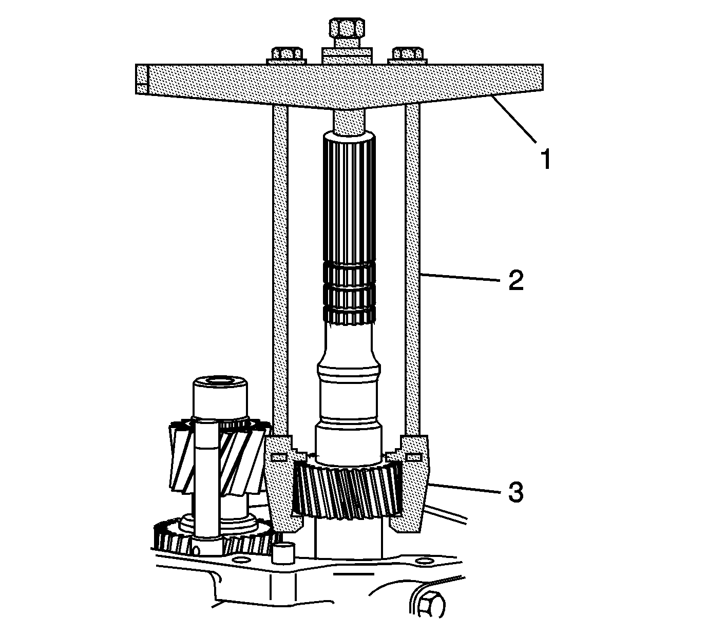
- Install
J 8433 puller
(1) ,
J 39431 remover and bolts
(3) and J 39431-4 (2) on the 5th speed driven gear.
- Remove the 5th speed driven gear.
Countershaft Gear Removal
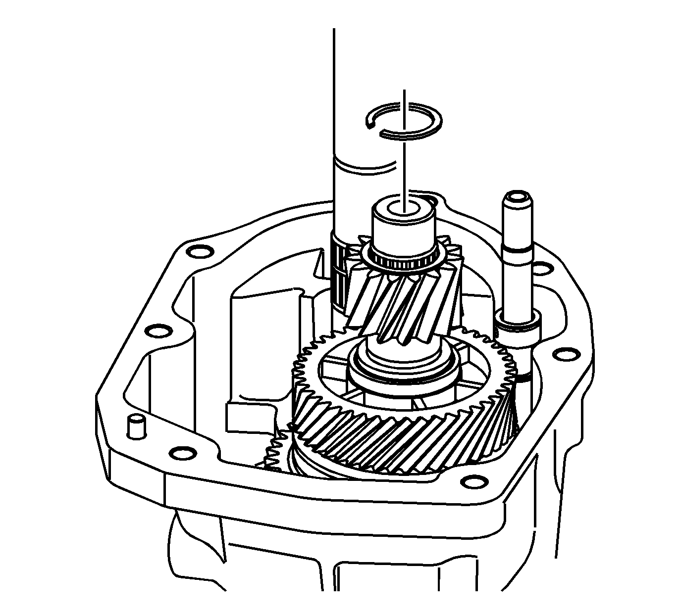
- Remove the counter shaft retainer ring.
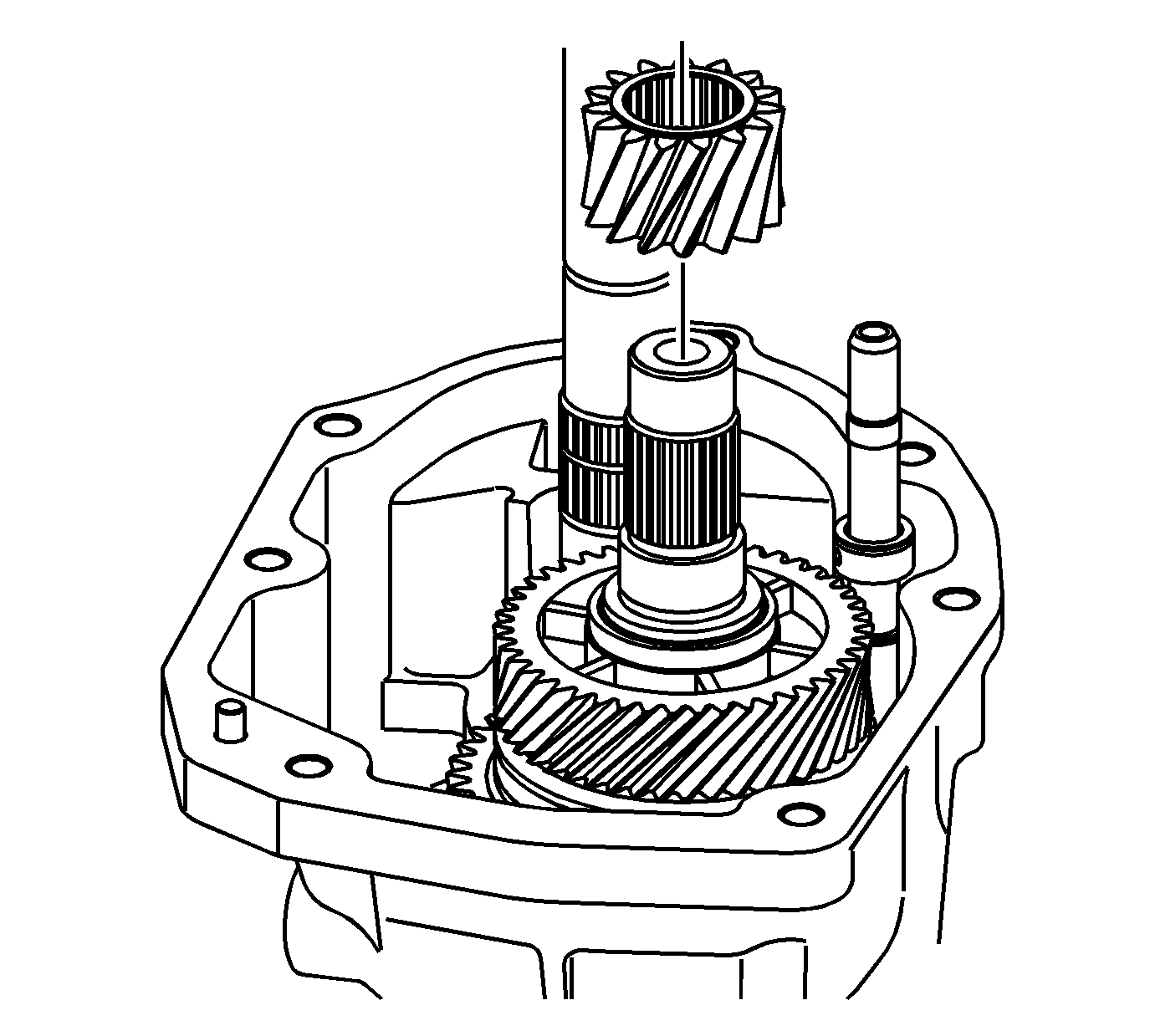
- Remove the countershaft gear.
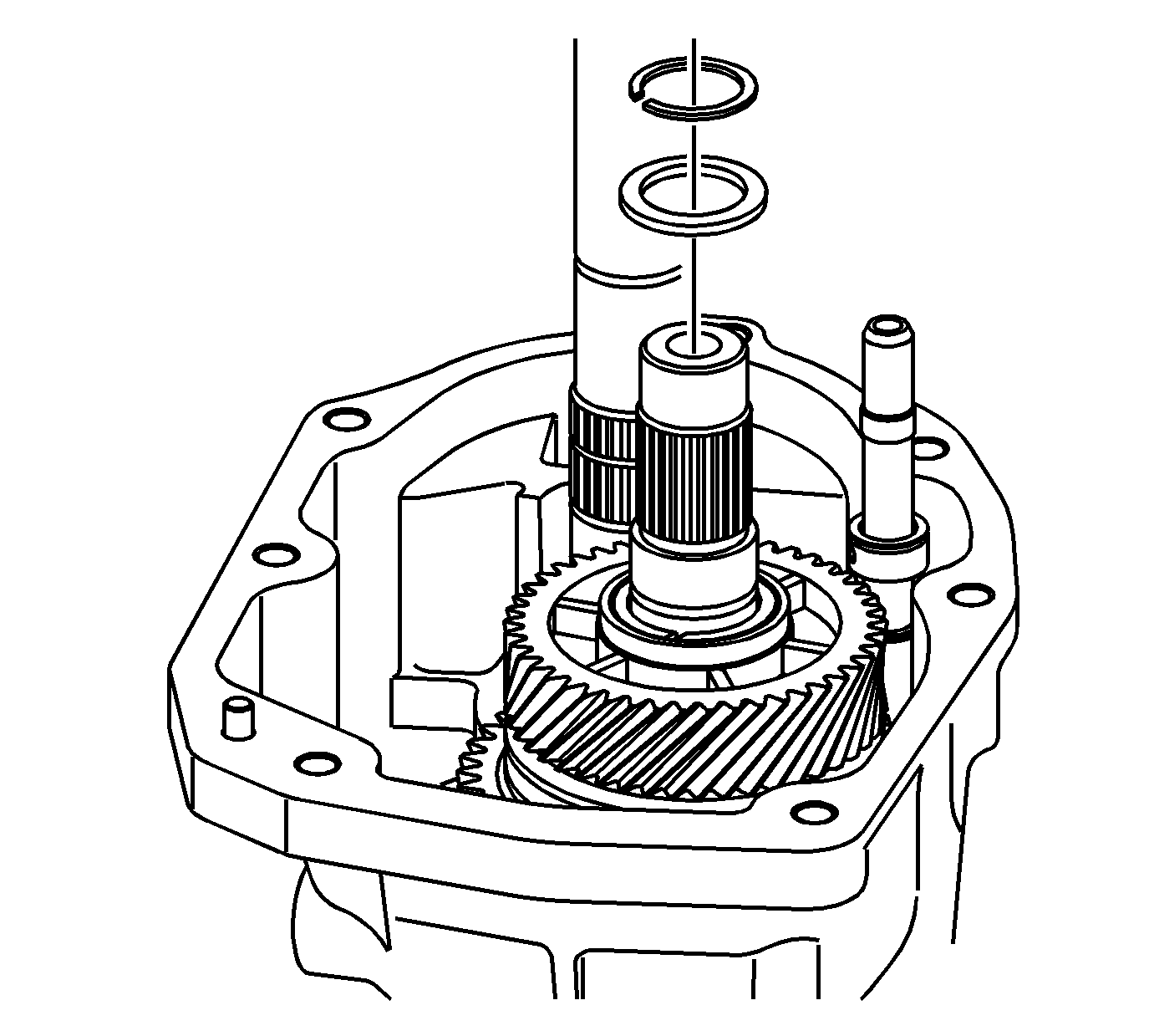
- Remove the countershaft retainer and
spacer.
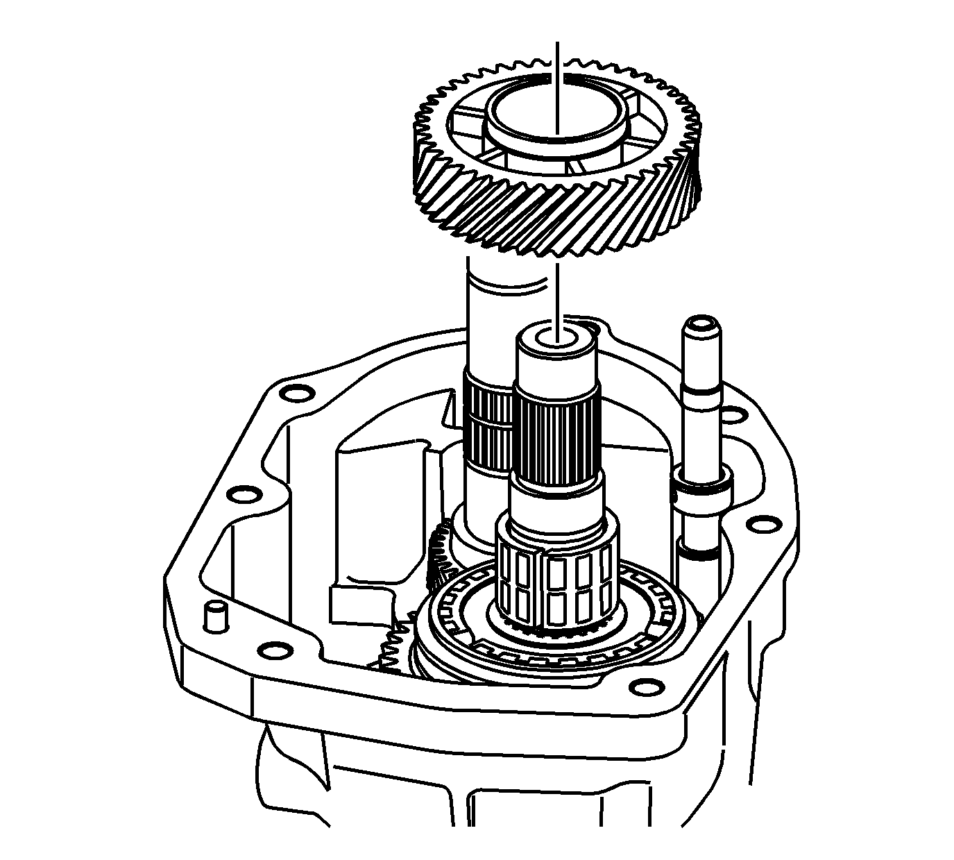
- Remove the gear from the countershaft.
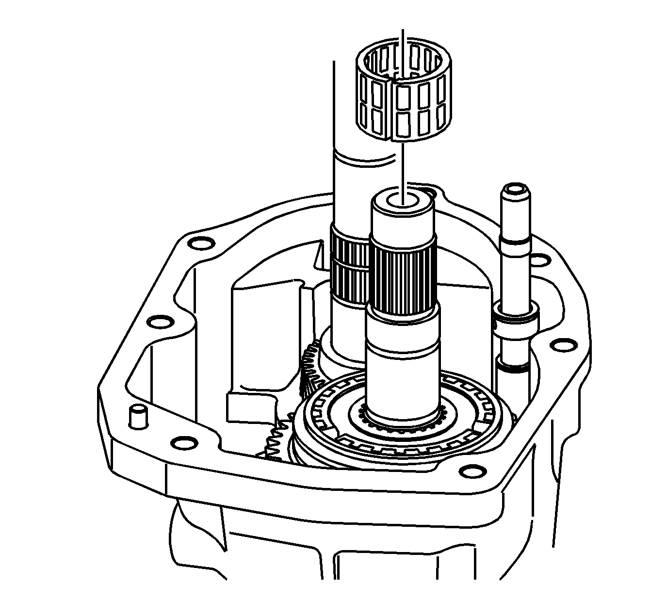
- Remove the needle bearing from the
countershaft.
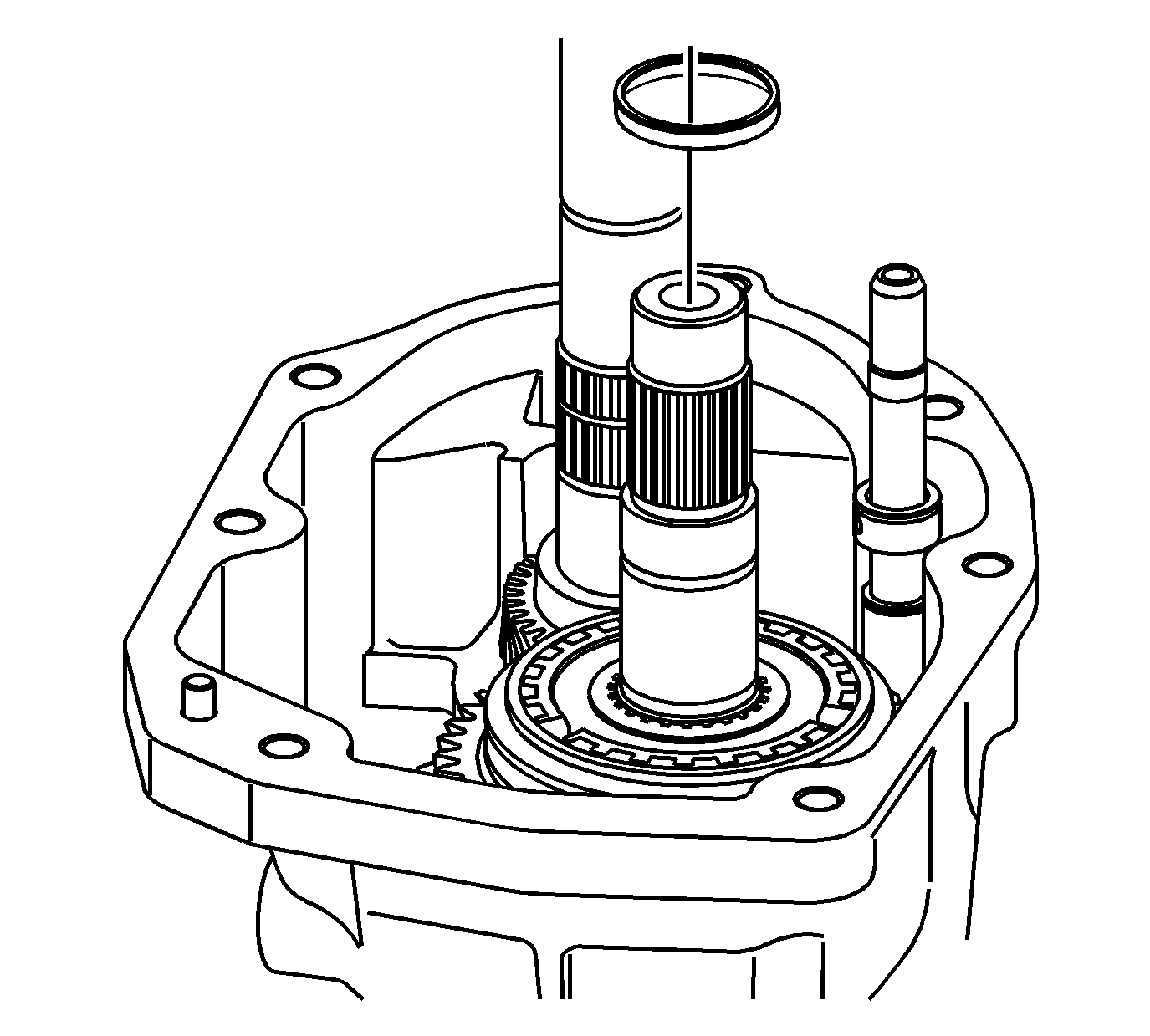
- Remove the spacer from the countershaft.
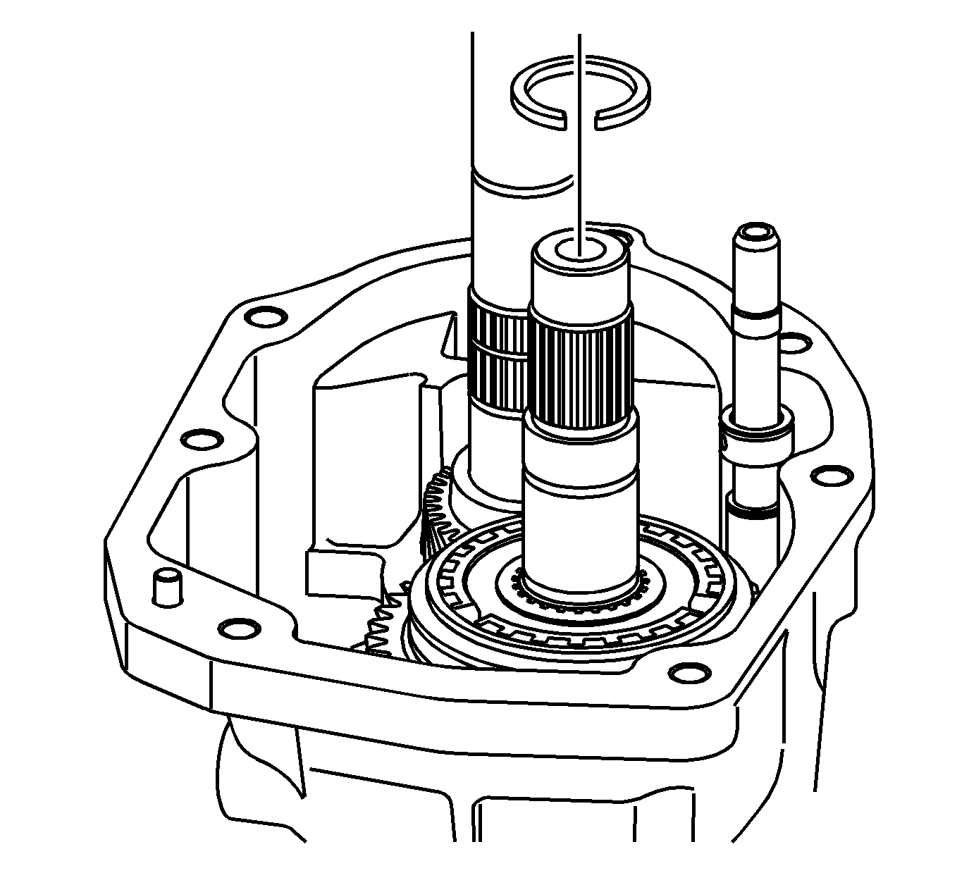
- Remove the retainer clip from the countershaft.
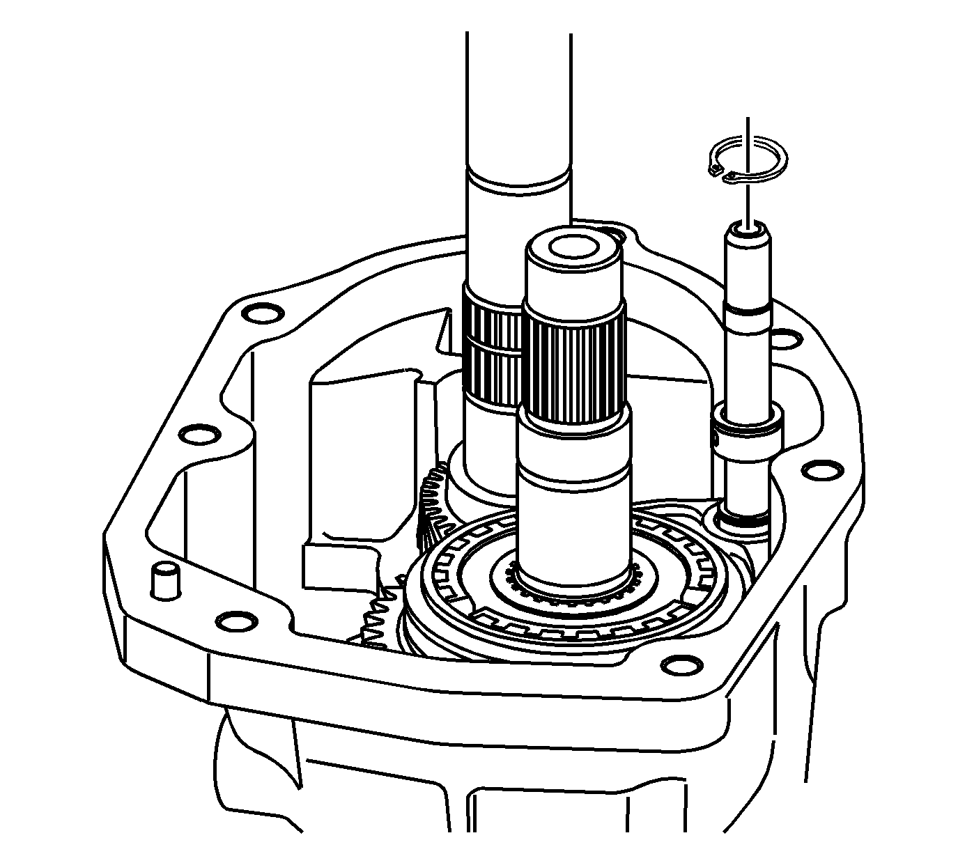
- Remove the 5th/6th speed shift fork
retainer ring.
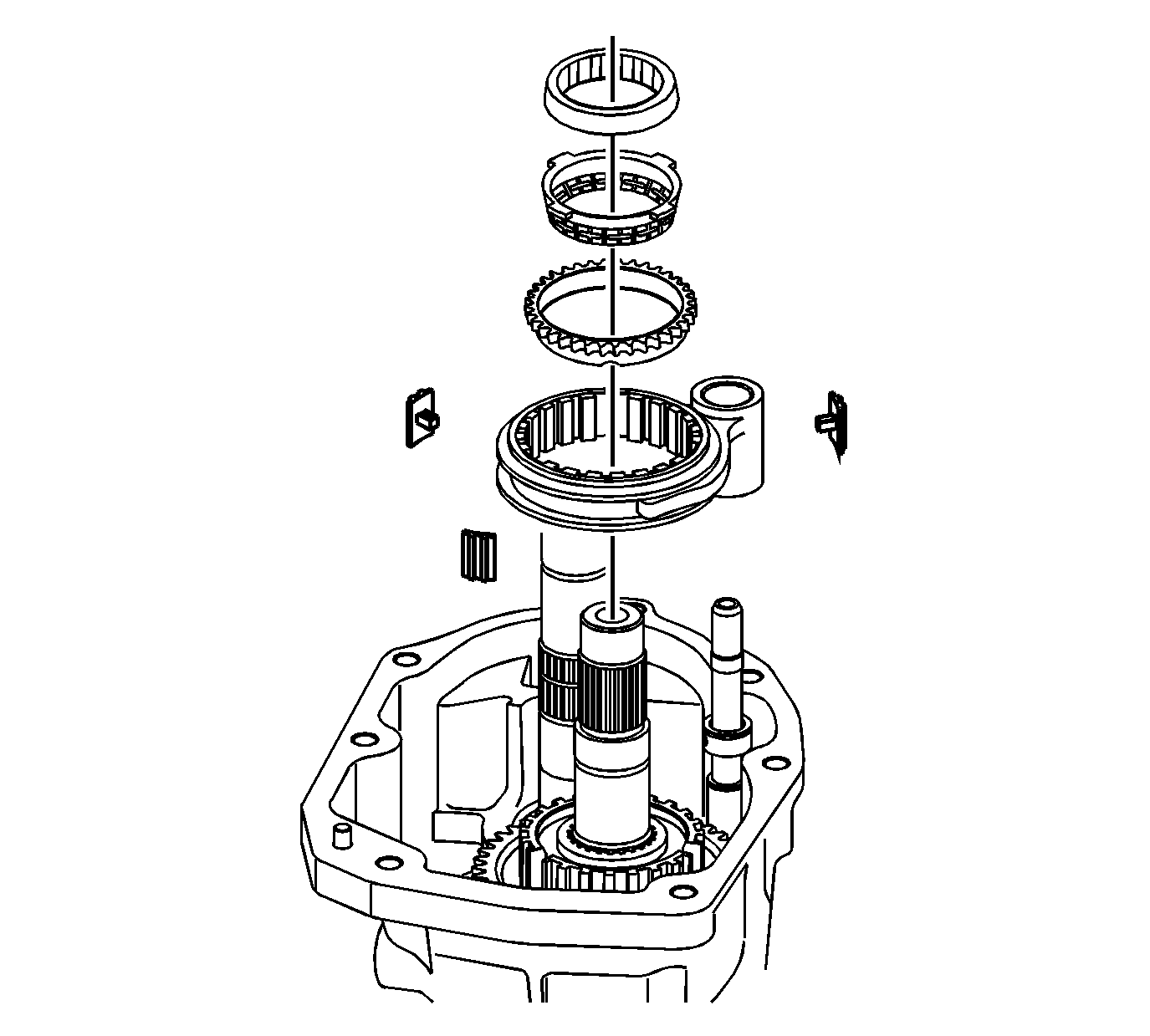
- Remove the following components:
| 9.1. | The 5th/6th shift fork |
| 9.2. | The synchronizer sleeve |
| 9.3. | The synchronizer inserts |
| 9.4. | The speed drive gear synchronizer blocking ring |
| 9.5. | The speed drive gear friction cone |
| 9.6. | The speed drive gear inner cone |
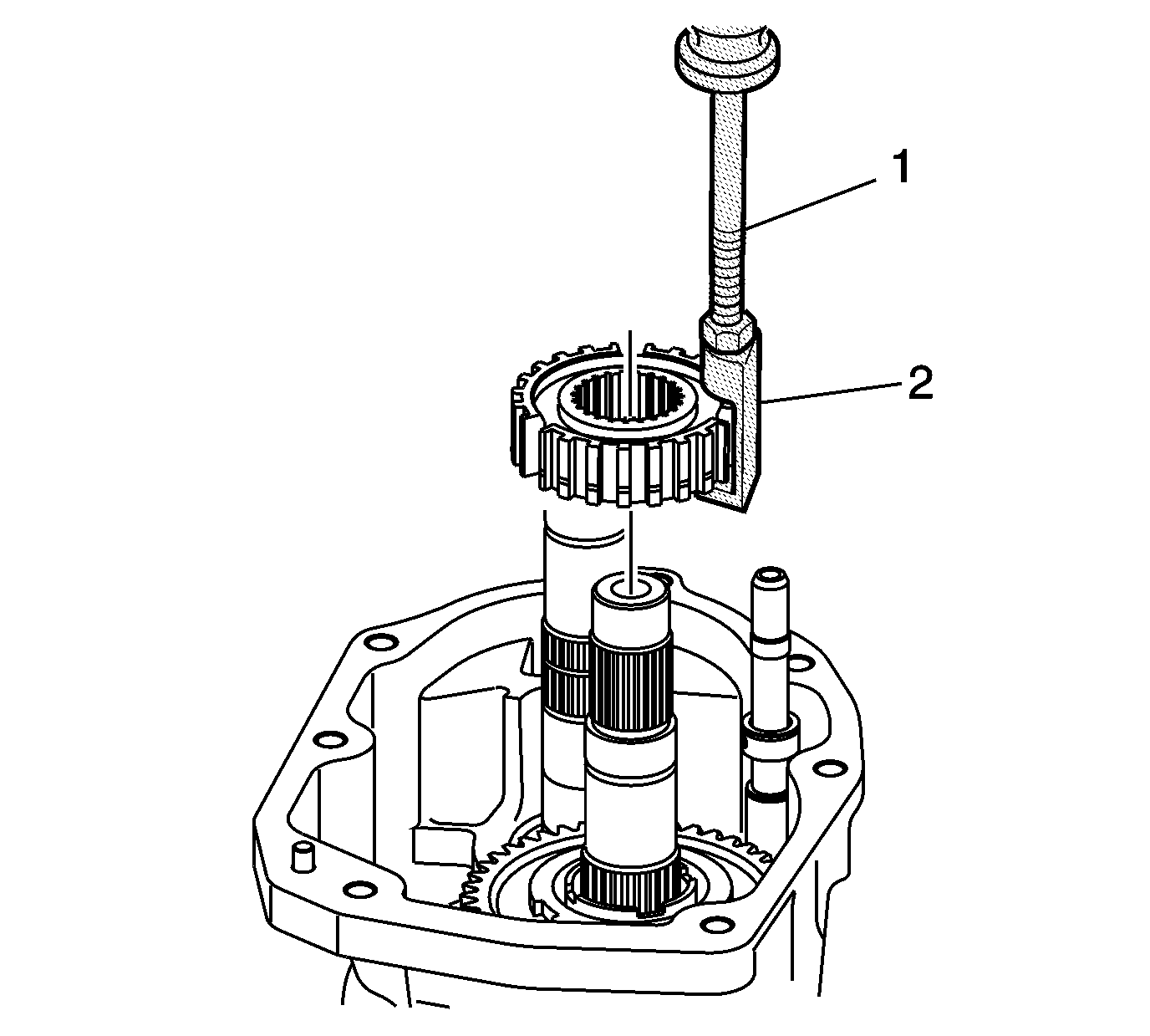
- Install the
DT 49139 remover
between the synchronizer hub assembly and synchronizer blocking ring.
- Remove the synchronizer hub assembly with
J 6125-1B hammer
.
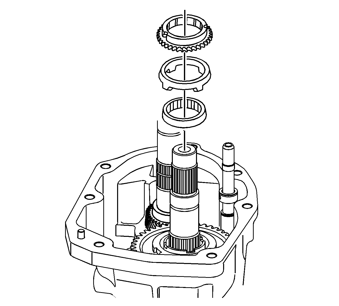
- Remove the following components:
| 12.1. | The speed drive gear synchronizer blocking ring |
| 12.2. | The speed drive gear friction cone |
| 12.3. | The speed drive gear inner cone |
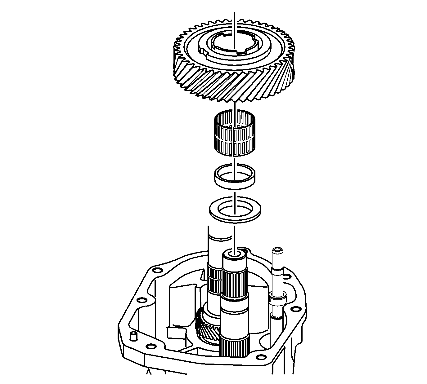
- Remove the 6th driven gear, caged needle
bearing, and spacer.
Transmission Case Removal
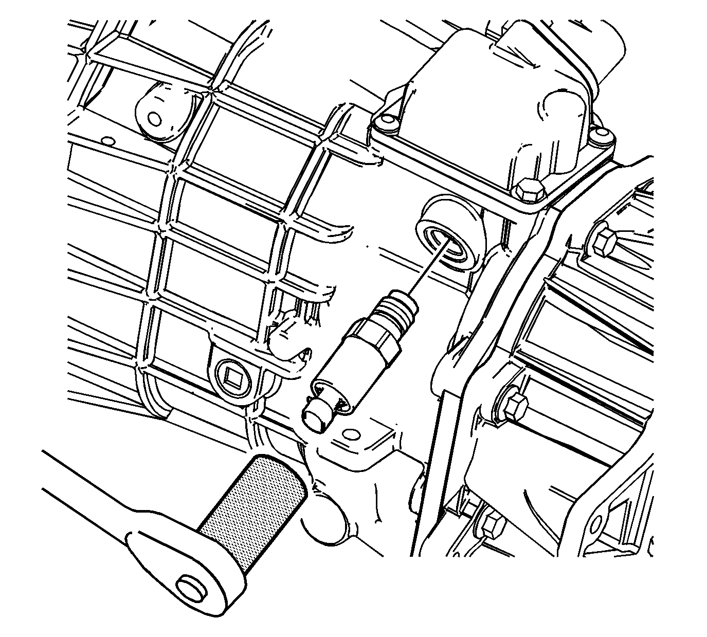
- Using
DT 48827 socket
, remove the computer aided gear select solenoid.
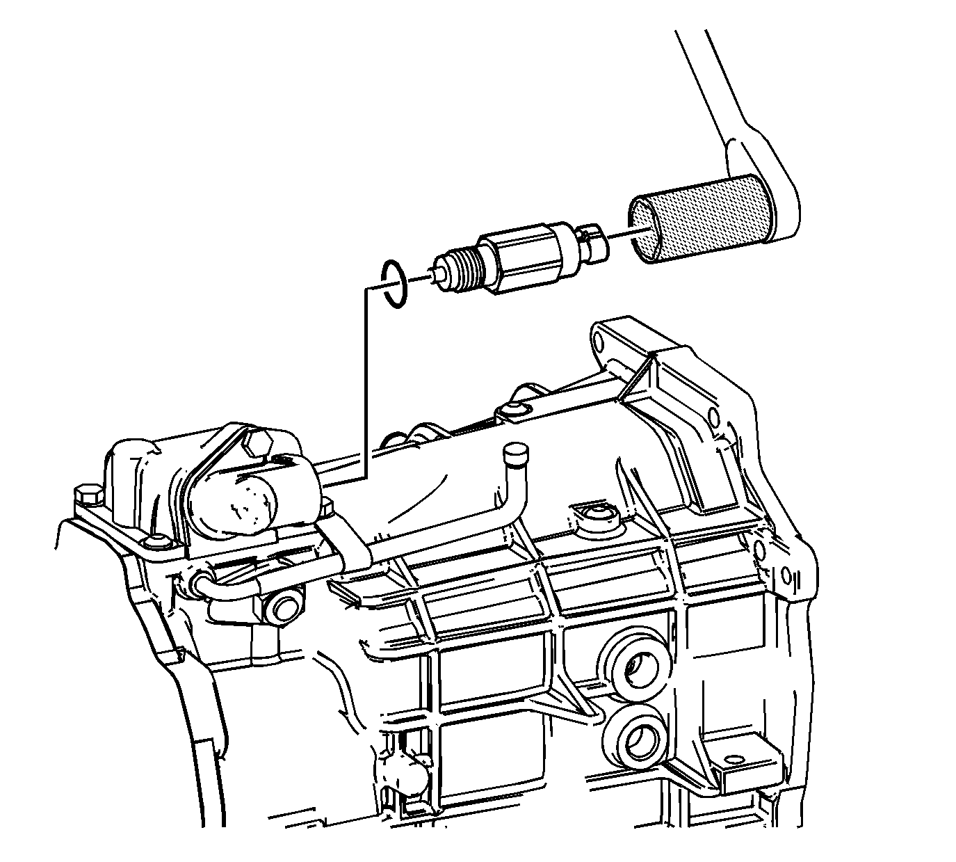
- Using
DT 48827 socket
, remove the reverse lockout solenoid from the reverse lockout body.
- Remove the O-ring seal from the reverse lockout solenoid and discard.
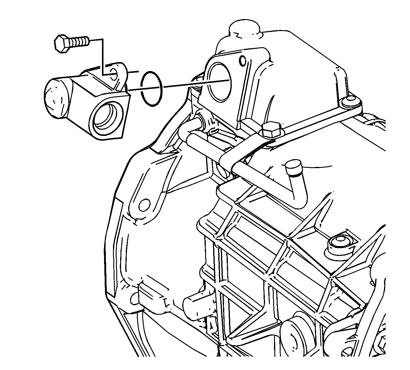
- Remove the reverse lockout assembly bolt and the reverse
lockout body.
- Remove the O-ring seal from the reverse lockout body and discard.
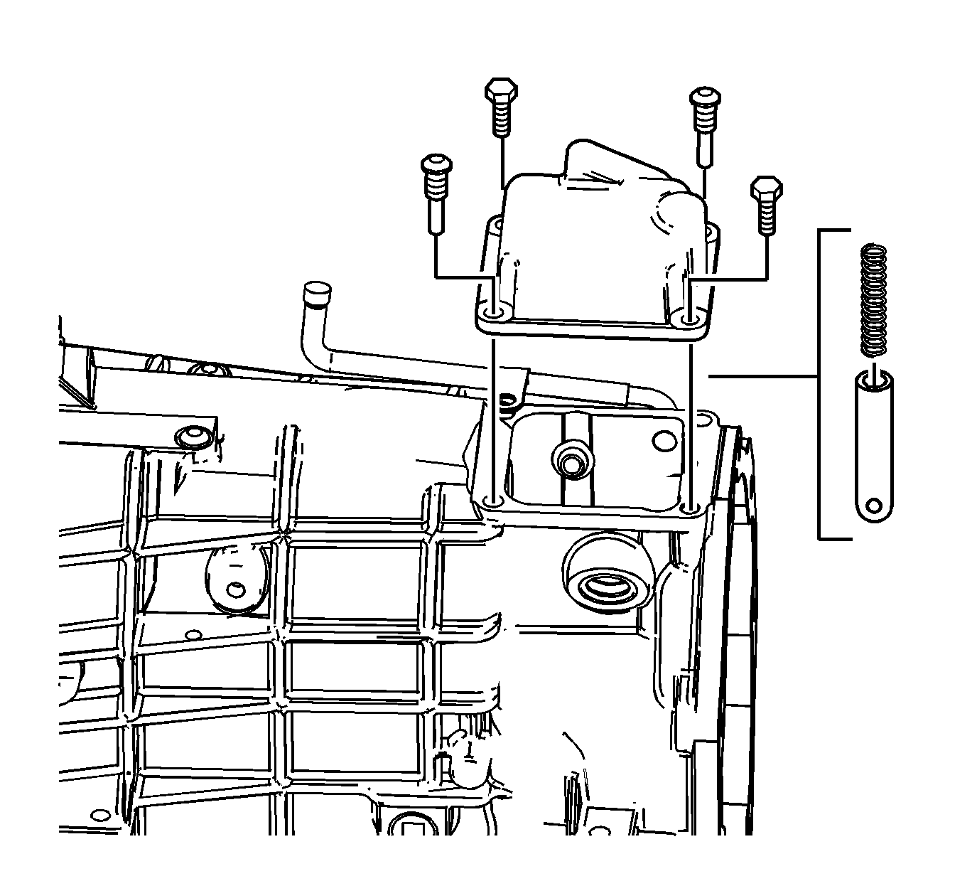
- Remove the shifter cover plate retainer bolts.
- Remove the shifter cover plate.
- Remove the spring and roller detent.
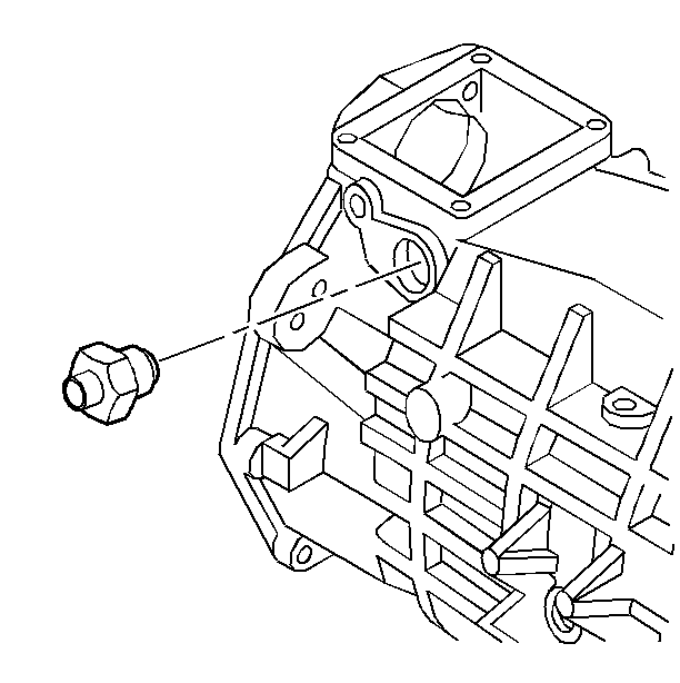
- Remove the shift detent assembly.
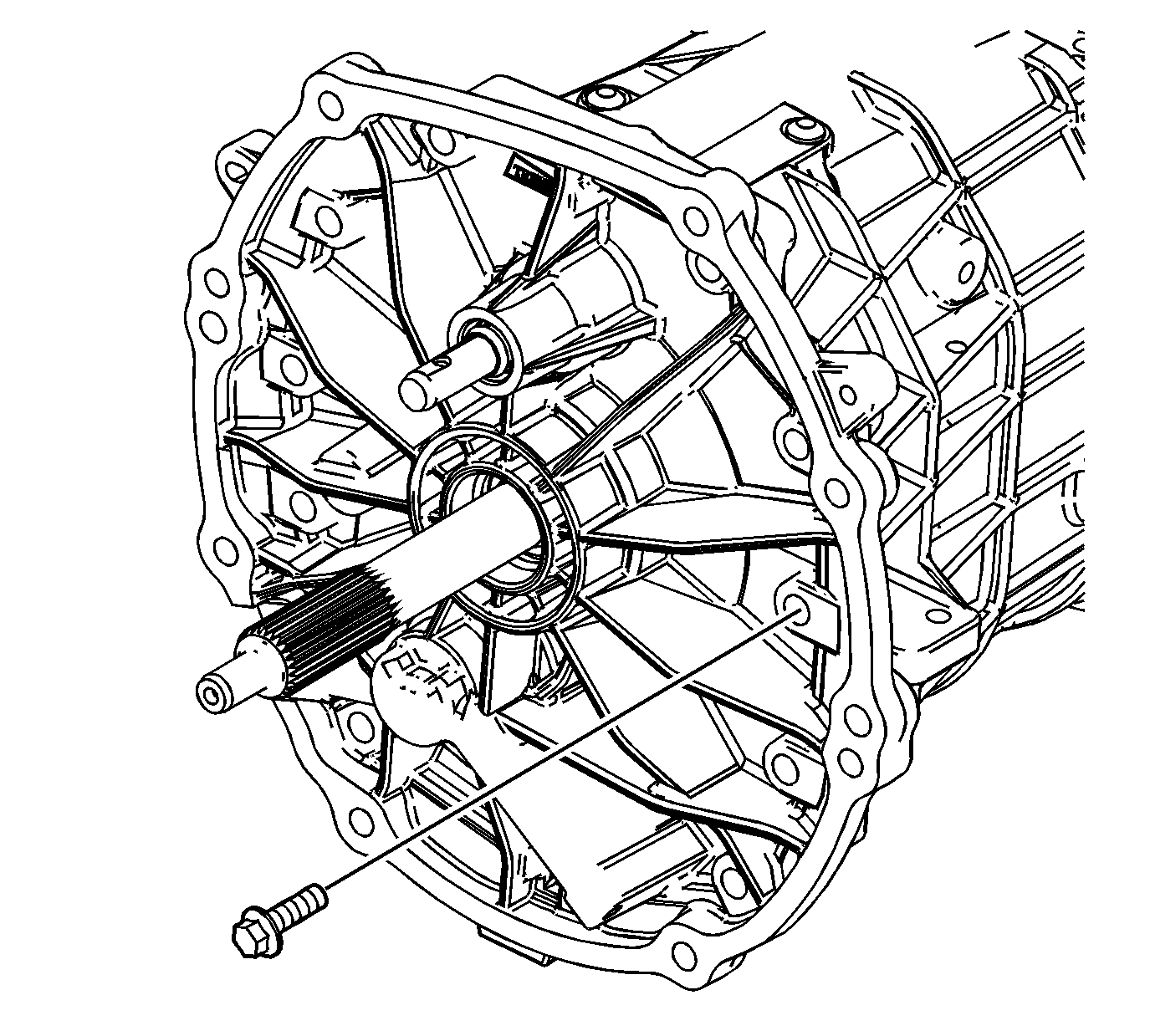
- Remove 8 of the 11 adapter plate
to transmission case bolts.
- Rotate the transmission into the vertical position.
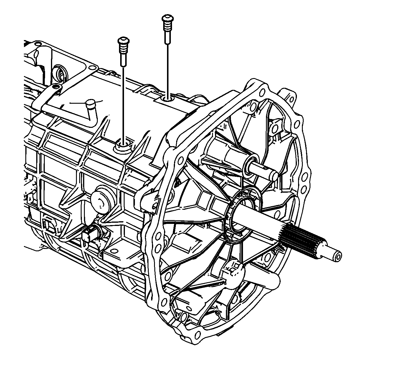
- Remove the 2 shift lever guide bolts.
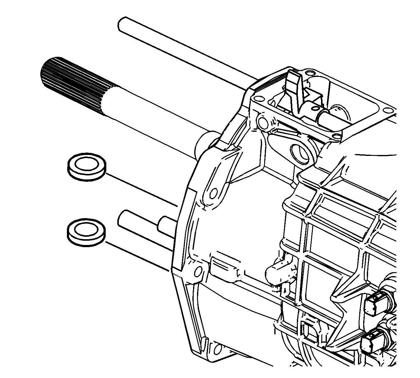
- Remove the magnets from the transmission case.
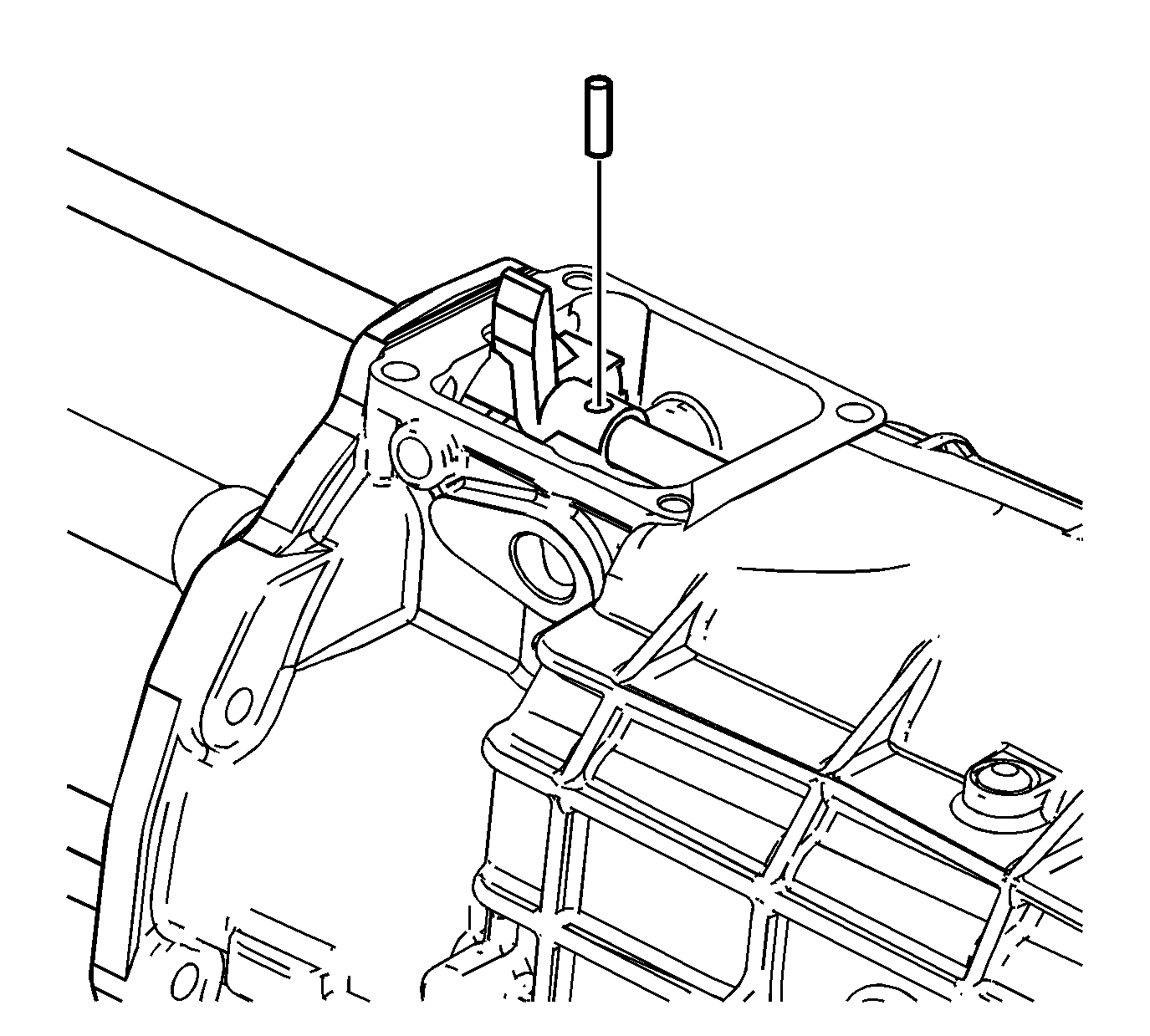
- Remove the offset lever roll pin by using a punch to
push the pin through the shift shaft.
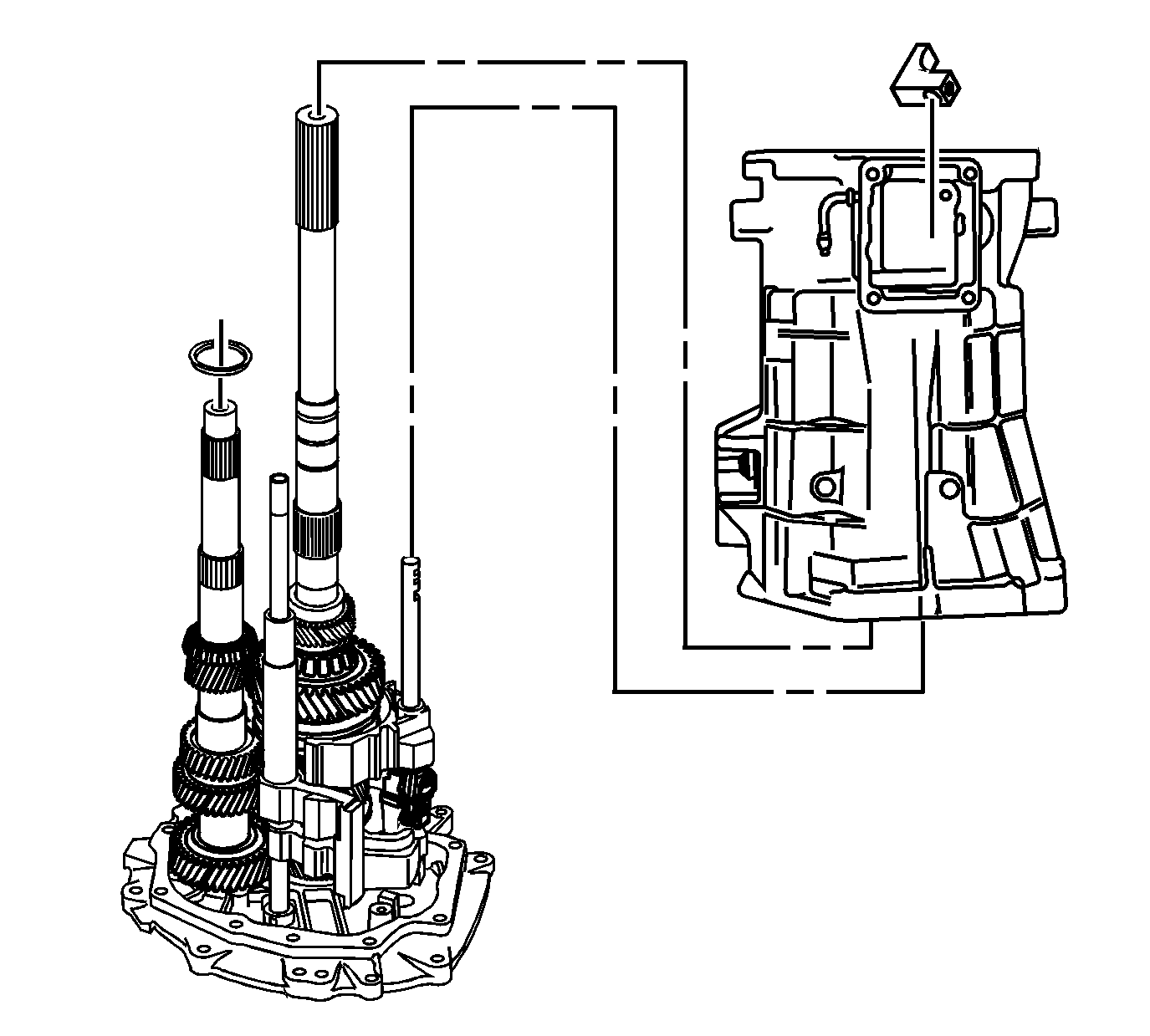
- Pry the transmission case from the
adapter plate.
- Remove the offset lever and the transmission case at the same time.
- Remove the 6th gear spacer from the countershaft.
Guide Plate Removal
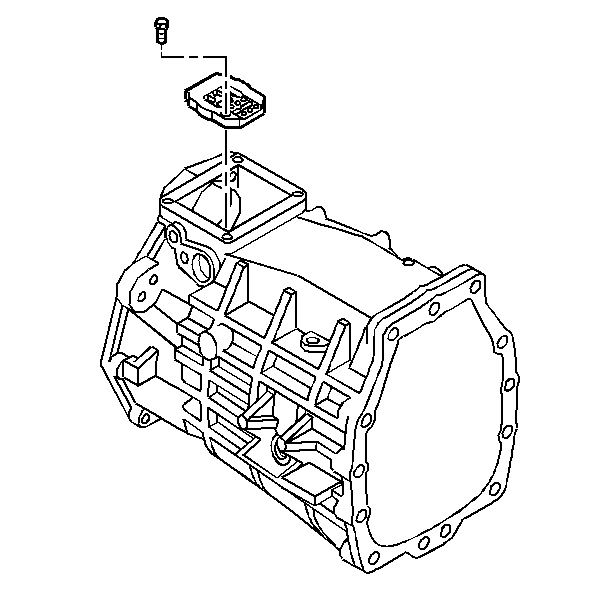
- Remove the detent guide plate attaching bolts.
- Remove the detent guide plate.
Reverse Lockout Assembly Disassemble
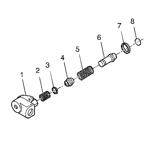
Warning: The reverse lockout assembly is under spring pressure. Exercise caution when removing the retainer ring, as bodily injury may result.
- Remove the O-ring (8) from the body (1).
- Remove the retainer ring (7) from the body (1).
- Remove the reverse lockout inner spring (2).
- Compress the reverse lockout plunger (6) and the collar (4) in a vise and remove the retainer ring (3).
- Remove the reverse lockout plunger (6).
- Remove the reverse lockout outer spring (5).
- Remove the reverse lockout collar (4).
Shift Shaft Assemblies and Gear Cluster Removal
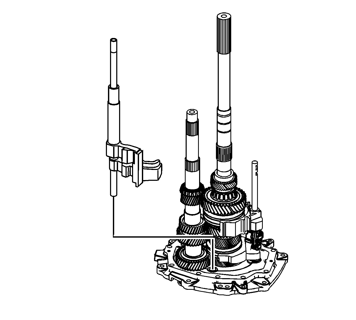
- Rotate the 5th/6th and the reverse
shift shaft levers off the shift interlock plate.
- Remove the 5th/6th and the reverse shift shaft assembly.
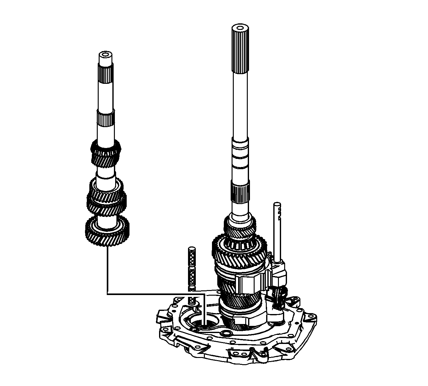
- Remove the countershaft. Lift up the mainshaft enough in order to remove the countershaft.
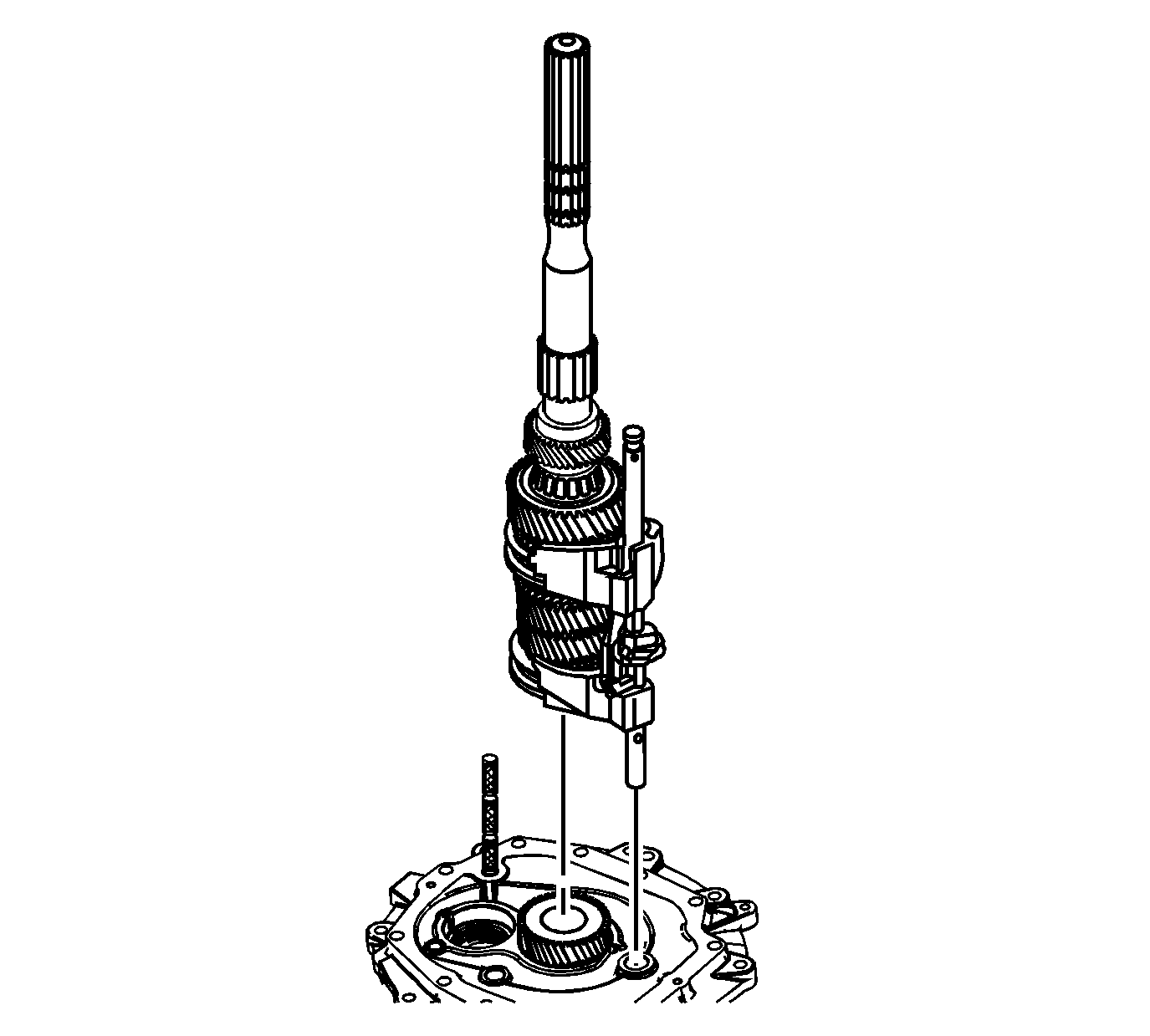
- Remove the mainshaft and the shift shaft components as an assembly.
Note: When removing the shift shaft be careful not to lose the dowel pin.
- Remove the shift shaft assembly from the mainshaft.
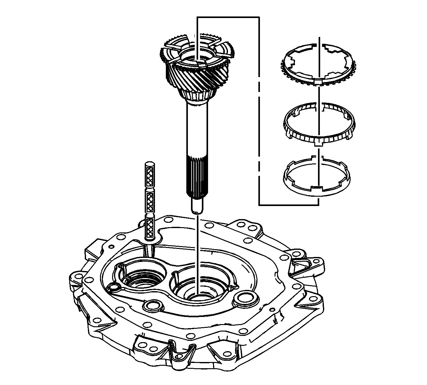
- Remove the following components from the adapter plate:
| • | 4th gear synchronizer blocking ring |
| • | 4th gear intermediate cone |


