Special Tools
| • | J 8092 Universal Driver Handle
|
| • | J 36017 Valve Seal Remover
|
| • | J 36190 Universal Driver Handle
|
| • | J 39433 Input Shaft Seal Installer
|
| • | J 39435 Bearing Race Installer
|
| • | J 39439-3 Bushing Installer
|
| • | J 39442 Mainshaft and Countershaft Press Adapter
|
| • | J 42464 Shift Shaft Seal lnstaller
|
| • | J 42496 Inner Shift Rail Inner Seal lnstaller
|
For equivalent regional tools, refer to
Special Tools.
Transmission Case
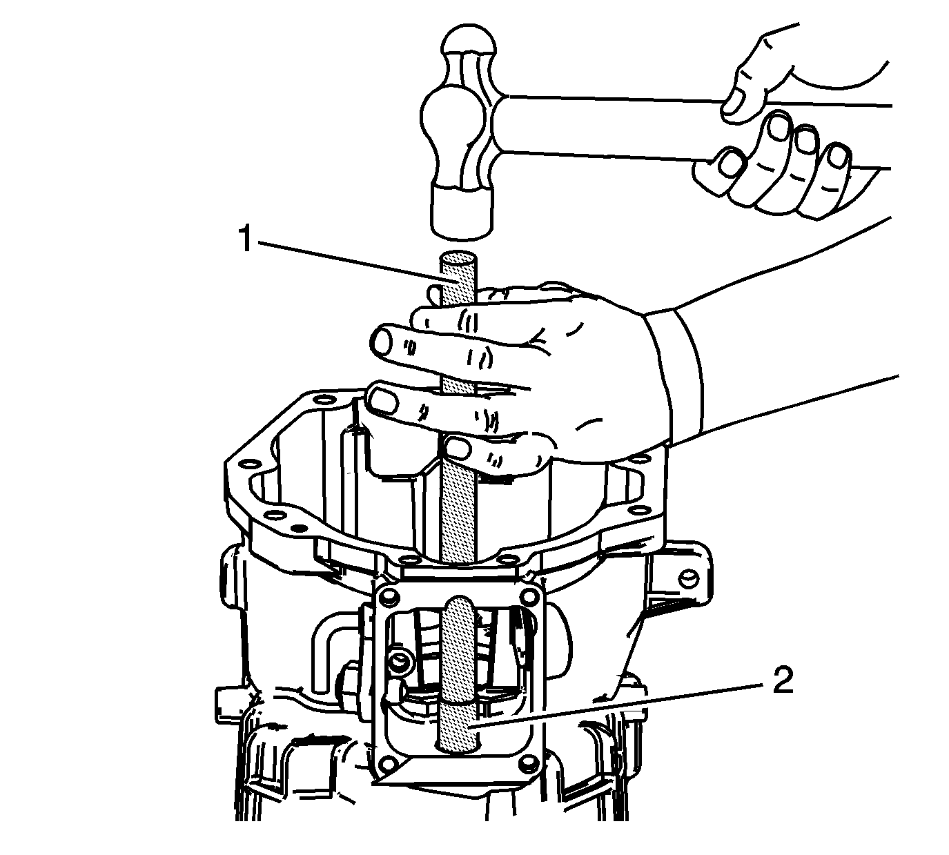
- Install the 1st/2nd and the 3rd/4th
shift shaft bushings. Use
J 36190 driver handle
and
J 39439-3 bushing installer
.
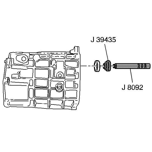
- Install the mainshaft bearing race, using the
J 8092 universal driver handle
and the
J 39435 race installer
.
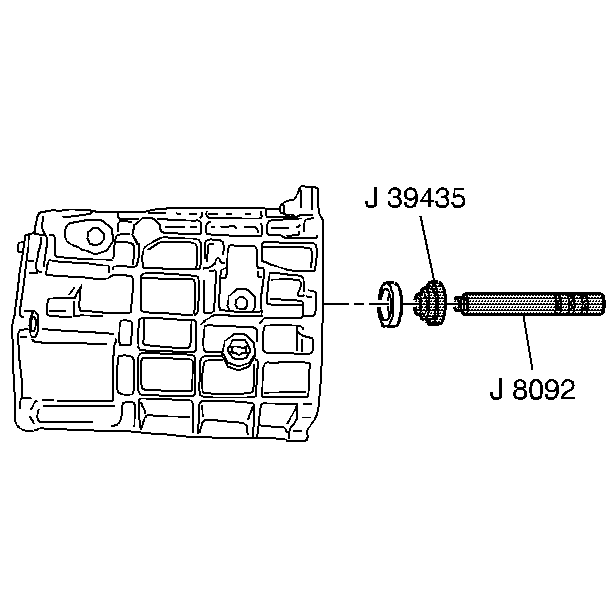
- Install the countershaft bearing race, using the
J 8092 universal driver handle
and the
J 39435 race installer
.
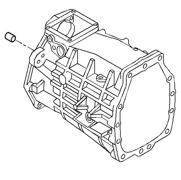
- Install the dowel pins.
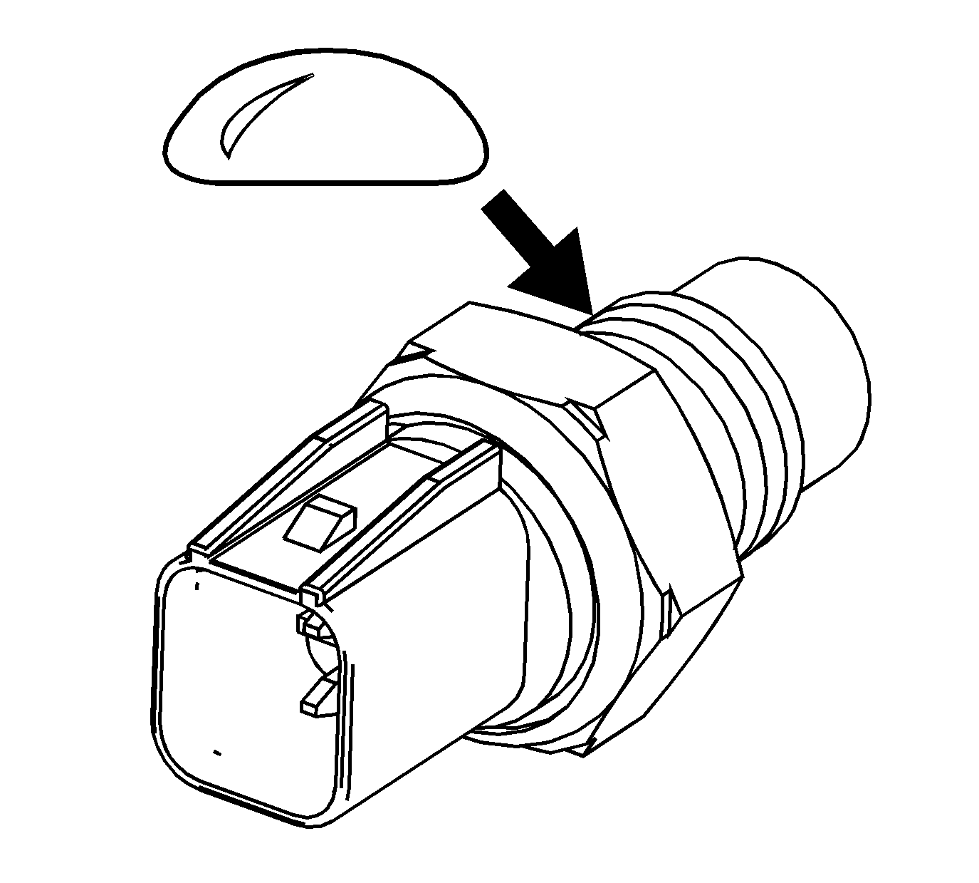
- Apply sealant GM P/N 12346004 (Canadian P/N 10953480)
or equivalent to the threads of the reverse lamp switch.
Caution: Refer to Fastener Caution in the Preface section.
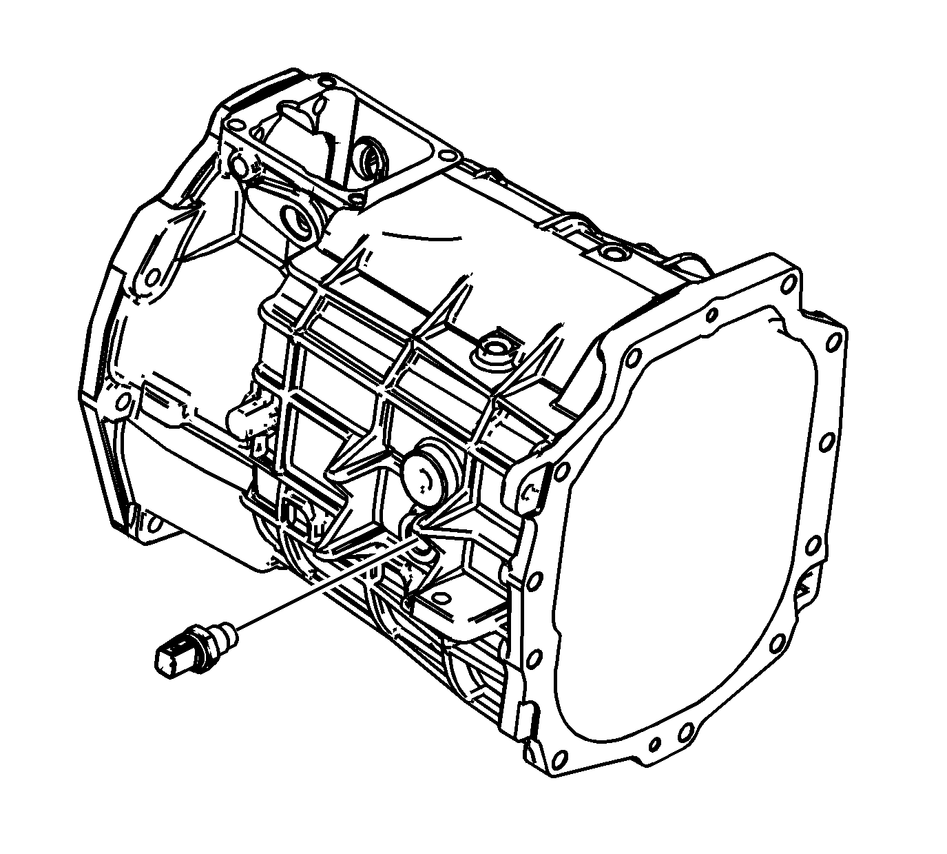
- Install the reverse lamp switch and tighten to
27 N·m (20 lb ft).
- Install the coolant temperature sensor and tighten to
39 N·m (29 lb ft).
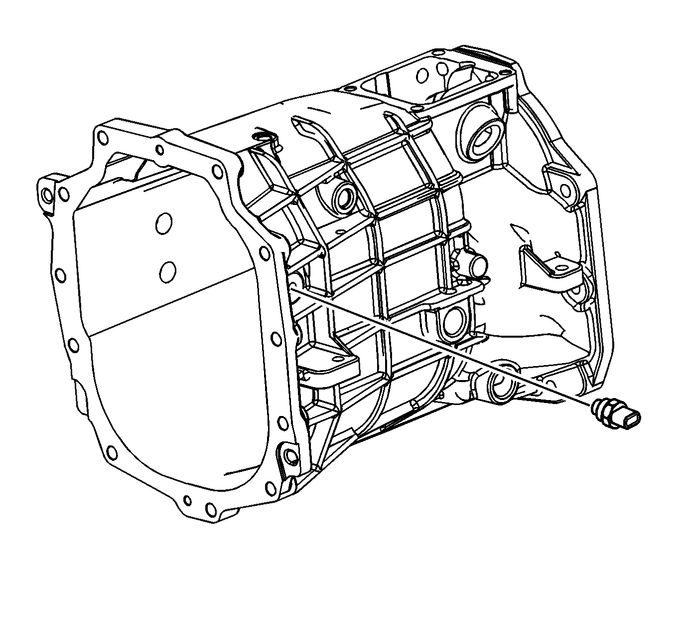
- Install the transmission case cooler line return fitting.
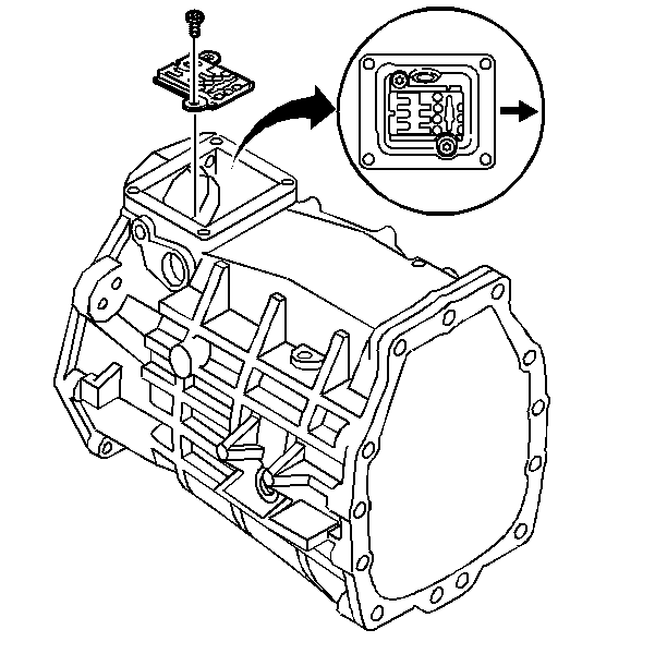
Caution: The H-pattern on the guide plate must face the extension housing. If the guide plate is installed incorrectly, then damage will occur.
- Install the guide plate and the guide plate bolts and tighten to
22 N·m (16 Ib ft).
Adapter Plate
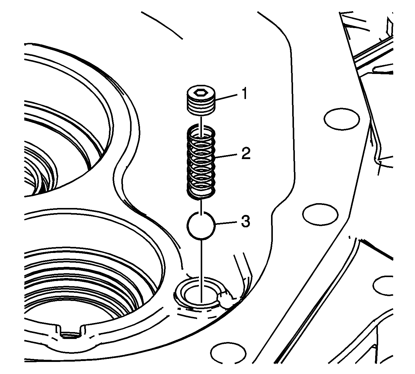
- Install the check ball (3).
- Install the spring (2).
- Install the plug (1).
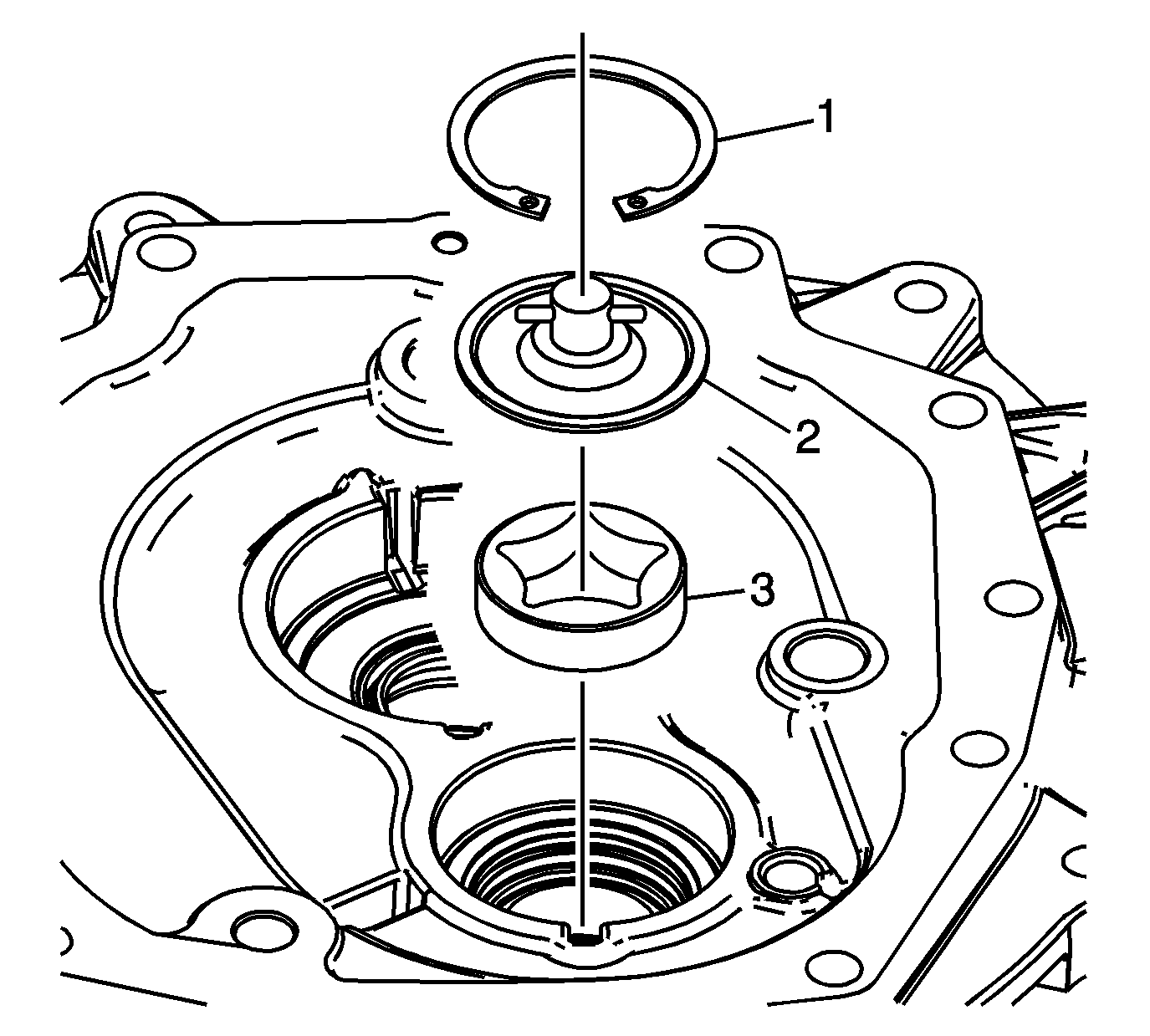
- Install the oil pump (3).
- Install the oil pump cover assembly (2).
- Install the retainer ring (1).
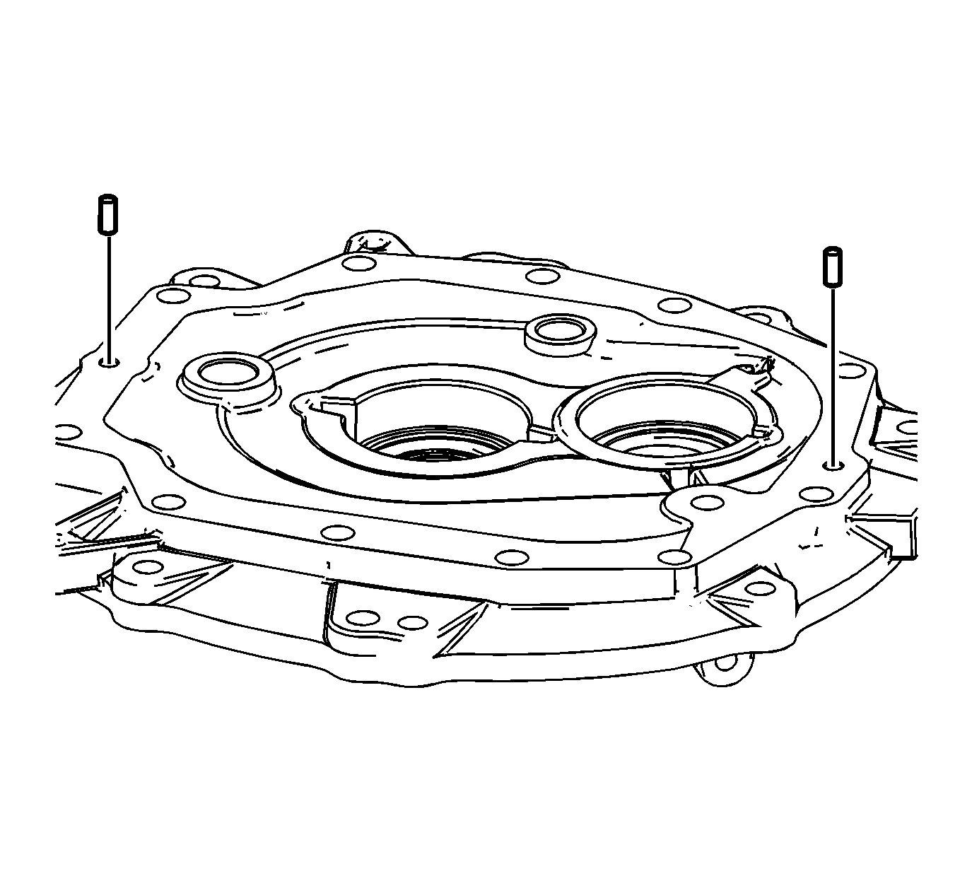
- Install the dowel pins.
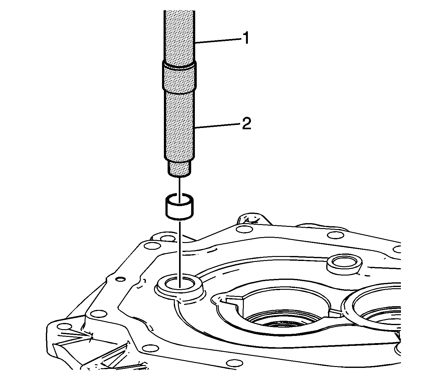
Caution: If the 1st/2nd, 3rd/4th speed shift shaft bushing is installed incorrectly it will interfere with the inner shift rail seal causing a leak.
- Install the 1st/2nd, 3rd/4th speed shift shaft bushing flush with adapter plate, using the
J 39439-3 bushing installer
(2) and
J 36190 universal driver handle
(1).
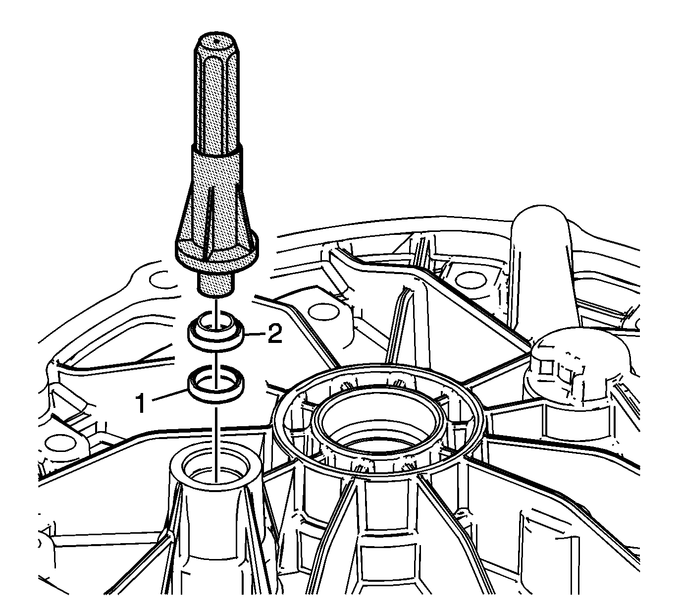
- Load the inner seal (1) and the outer seal (2)
onto
J 42496 seal installer
.
- Install the shift rail seal (1 and 2) using
J 42496 seal installer
.
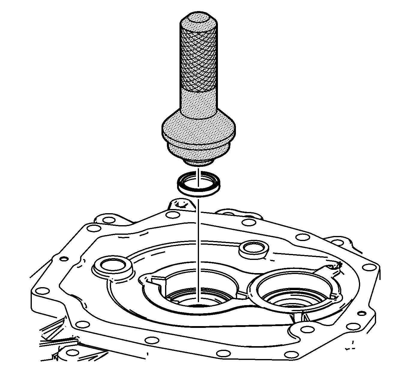
- Install the input shaft seal, using the
J 39433 shaft seal installer
.
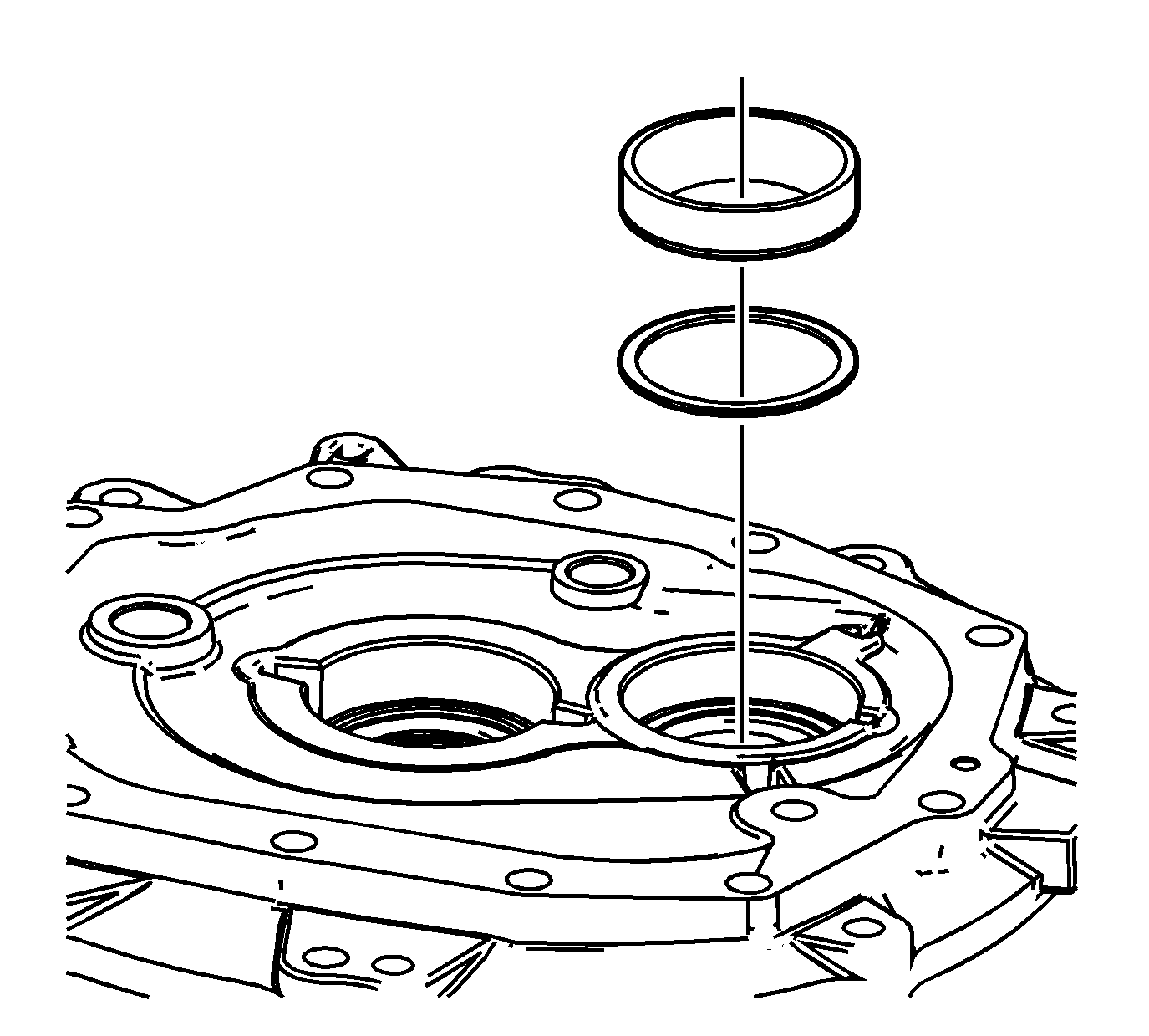
- Install the countershaft bearing shim
and bearing race. Refer to Input Shaft, Mainshaft and Countershaft in
Shimming Procedures.
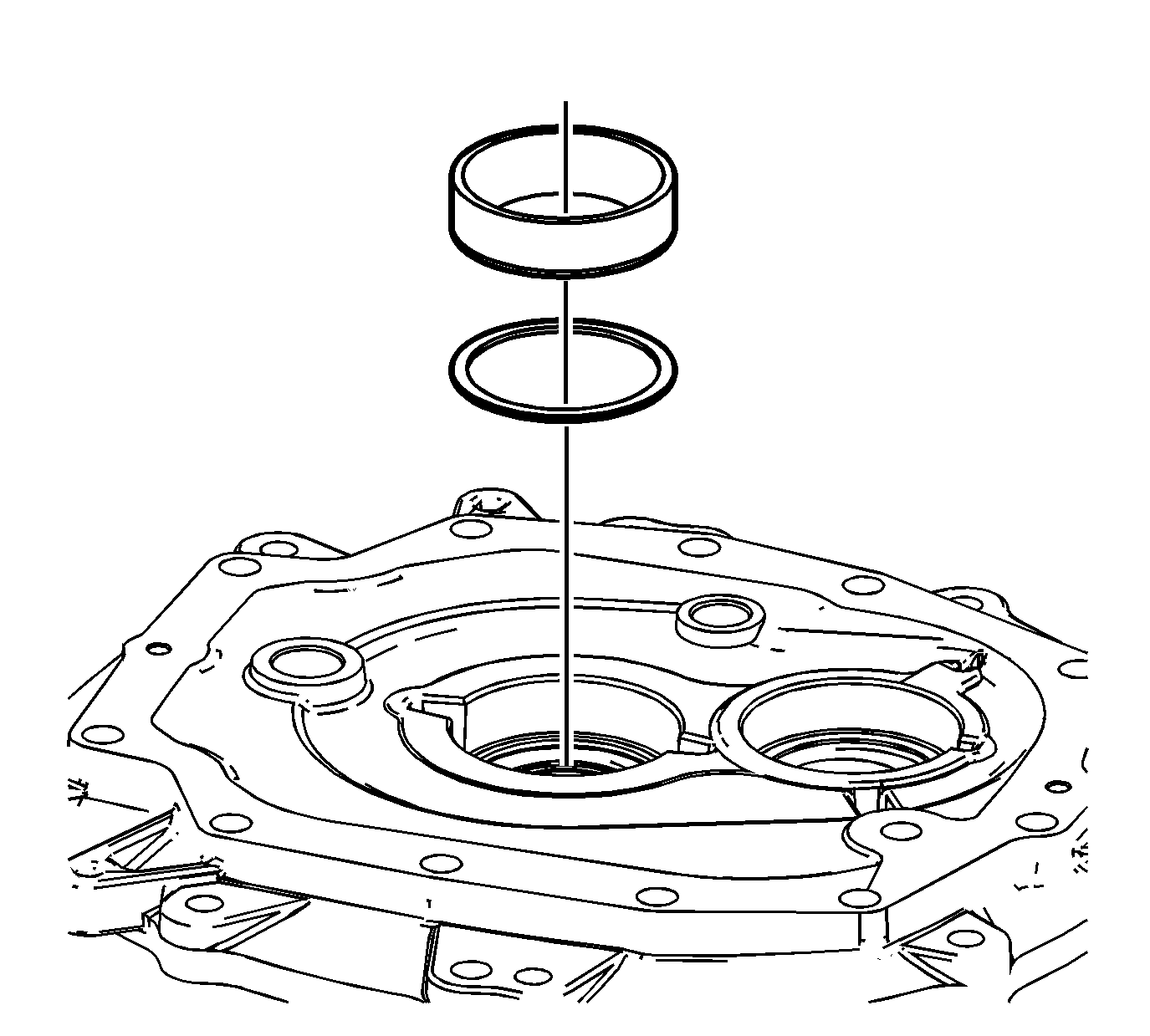
- Install the input shaft bearing shim
and bearing race. Refer to Input Shaft, Mainshaft and Countershaft in
Shimming Procedures.
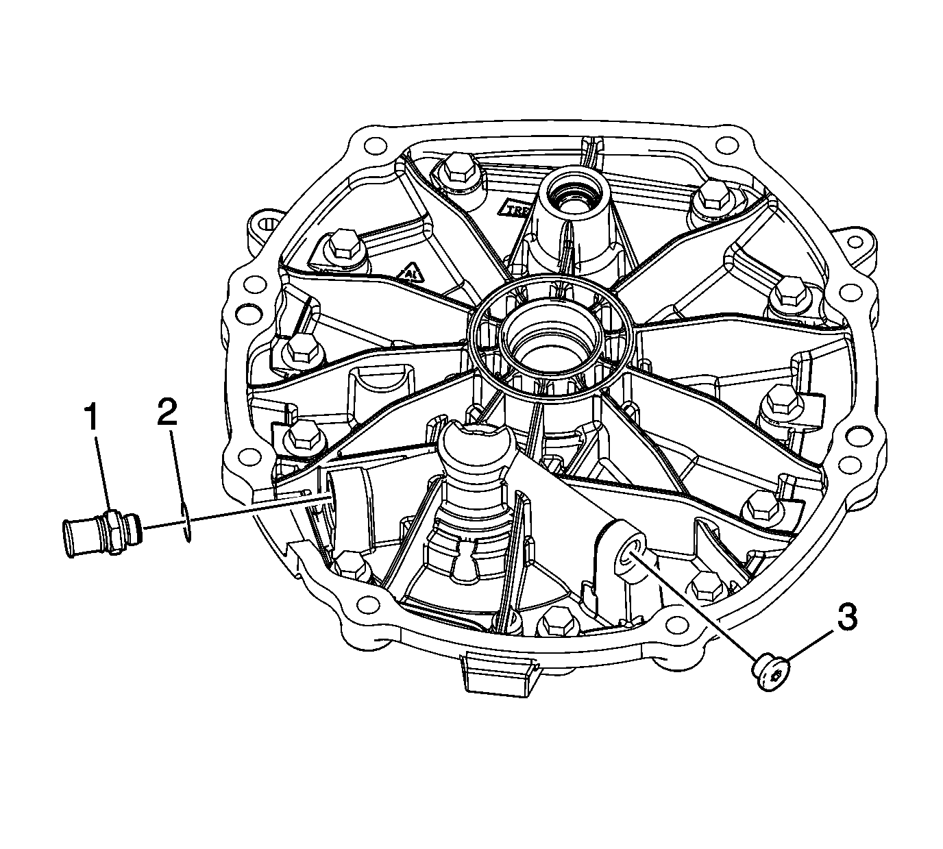
- Install the adapter plate
pump plug (3).
- Install the pump outlet cooler fitting seal (2) and fitting (1).
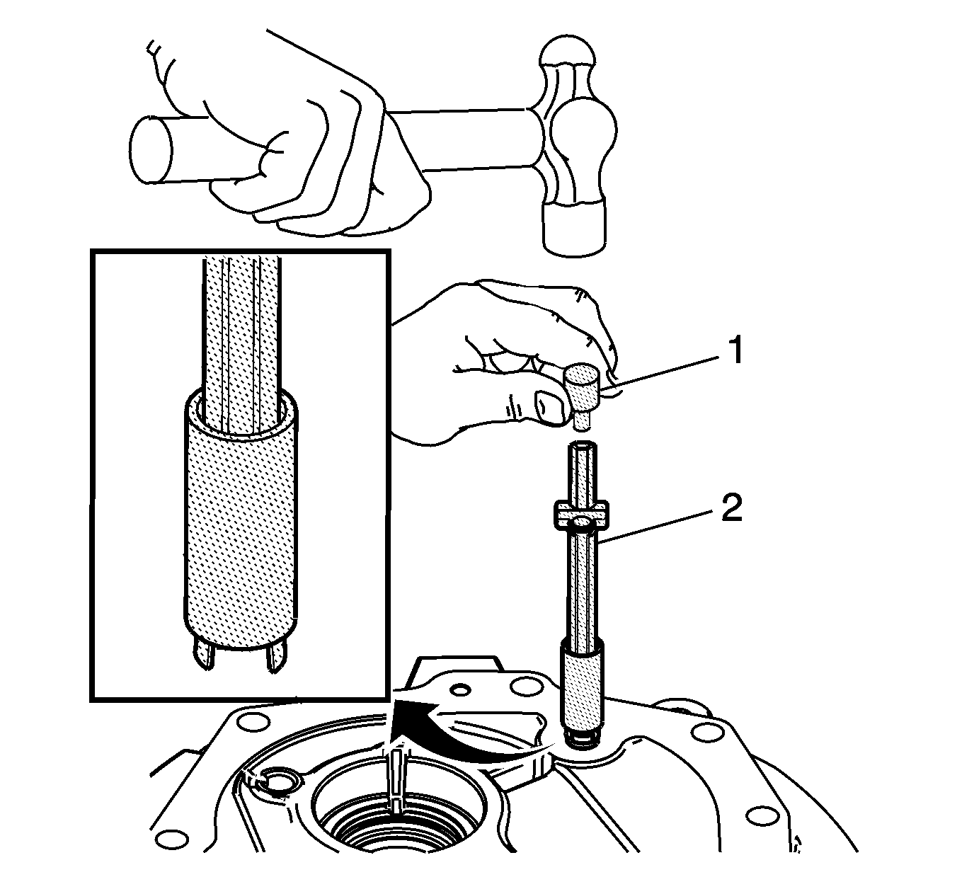
- Attach
J 36017 seal remover
within the groove at the base of the oil filter assembly. Slide the collar of the tool down to grasp the oil filter assembly.
- Place the oil filter assembly with
J 36017 seal remover
(2) attached onto the adapter plate.
- Using
J 39442 press adapter
(1), tap the oil filter assembly into place with a hammer. Remove
J 36017 seal remover
(2).


