Steering Wheel Theft Deterrent Lock Replacement Manual
Special Tools
J 42640 Steering Column Lock Pin
Removal Procedure
- Disable the SIR system. Refer to SIR Disabling and Enabling.
- Remove the trim covers from the upper and lower steering column. Refer to Steering Column Trim Cover Replacement.
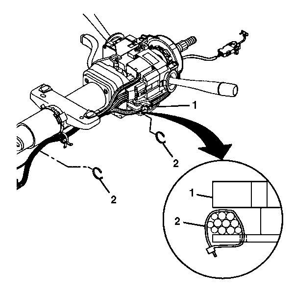
- Remove the wire harness straps (2) from the steering column tilt head assembly (1) and the column.
- Install J 42640 to the steering column.
- Remove the steering column tilt head assembly. Refer to Steering Column Tilt Head Housing Replacement.
- Remove the steering wheel theft deterrent lock.
Warning: Refer to SIR Warning in the Preface section.

Note: If the steering column connectors are disconnected with the ignition in the ON position, the BCM will enter a fail enable mode and prevent steering column lock operation. The PCM will also inhibit vehicle motion by disabling fuel. To clear the BCM fail enable mode, disconnect the BCM fuse #25 for 15 seconds.
Installation Procedure
- Install the steering wheel theft deterrent lock.
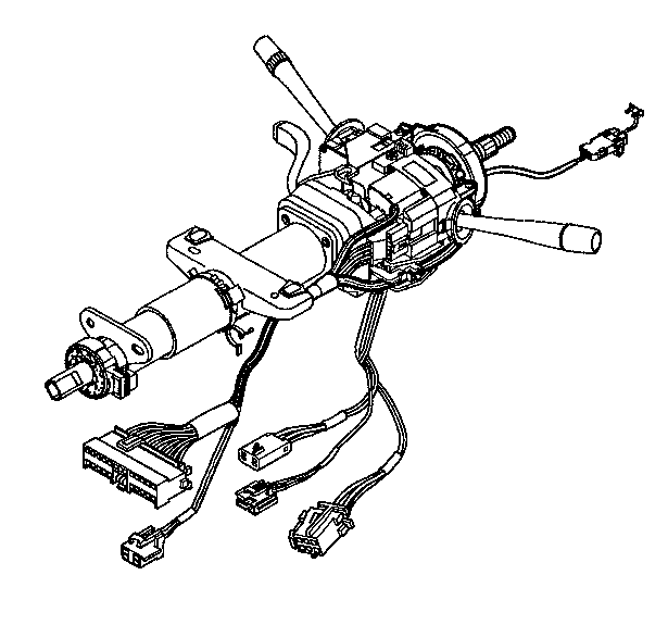
- Route the wire harness assembly along the steering column jacket assembly.
- Remove J 42640 from the steering column.
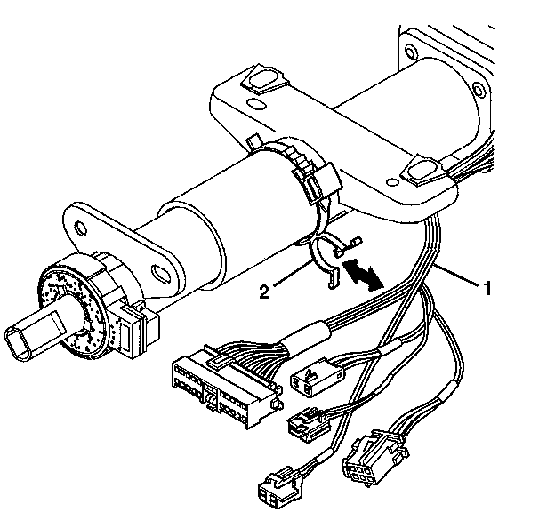
- Install the wire harness assembly (1) into the wire harness strap (2).
- Install new wire harness straps (2) to the steering column assembly (1) and the column.
- Install the steering column tilt head assembly. Refer to Steering Column Tilt Head Housing Replacement.
- Install the trim covers to the upper and lower steering column. Refer to Steering Column Trim Cover Replacement.
- Enable the SIR system. Refer to SIR Disabling and Enabling.


Steering Wheel Theft Deterrent Lock Replacement Telescoping
Special Tools
J 42640 Steering Column Lock Pin
Removal Procedure
- Disable the SIR system. Refer to SIR Disabling and Enabling.
- Remove the upper and lower steering column trim covers. Refer to Steering Column Trim Cover Replacement.
- Remove the wire harness straps (2) from the tilt head assembly (1) and the column.
- Install J 42640 to the steering column.
- Remove the tilt head assembly. Refer to Steering Column Tilt Head Housing Replacement.
- Remove the steering wheel theft deterrent.
Warning: Refer to SIR Warning in the Preface section.

Note: If the steering column connectors are disconnected with the ignition in the ON position, the BCM will enter a fail enable mode and prevent steering column lock operation. The PCM will also inhibit vehicle motion by disabling fuel. To clear the BCM fail enable mode, disconnect the BCM fuse #25 for 15 seconds.
Installation Procedure
- Install the steering wheel theft deterrent.
- Route the wire harness assembly along the steering column jacket assembly.
- Install the wire harness assembly (1) into the wire harness strap (2).
- Install the tilt head assembly. Refer to Steering Column Tilt Head Housing Replacement.
- Remove J 42640 from the steering column.
- Install the upper and lower trim covers. Refer to Steering Column Trim Cover Replacement.
- Enable the SIR system. Refer to SIR Disabling and Enabling.


