For 1990-2009 cars only
Special Tools
J 39400-A Halogen Leak Detector
Removal Procedure
- Recover the refrigerant from the A/C system. Refer to Refrigerant Recovery and Recharging.
- Remove the battery. Refer to Battery Replacement.
- Remove the intake manifold. Refer to Intake Manifold Replacement.
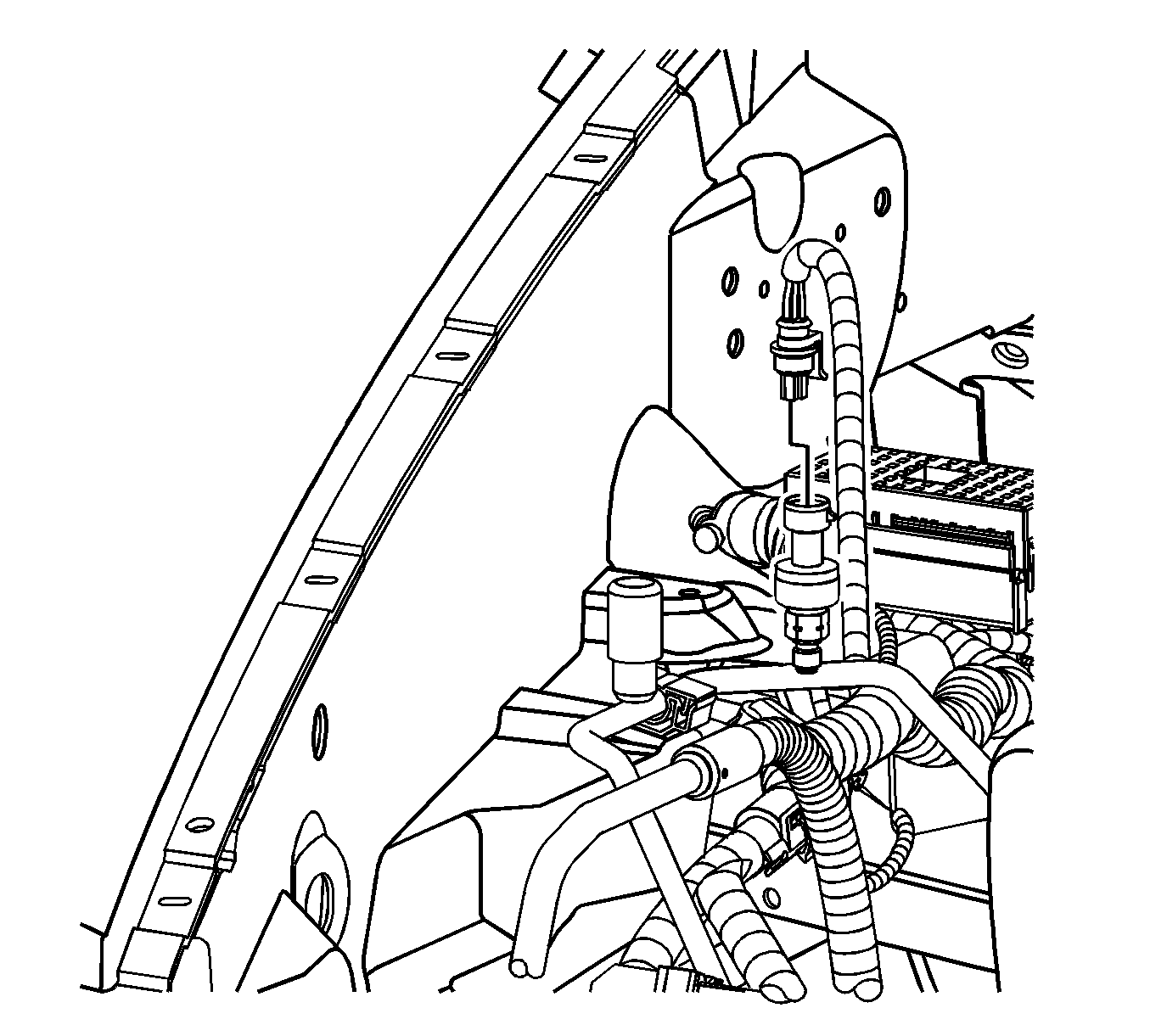
- Disconnect the front evaporator inlet line from the body retaining clip.
- Disconnect the refrigerant pressure sensor electrical connector.
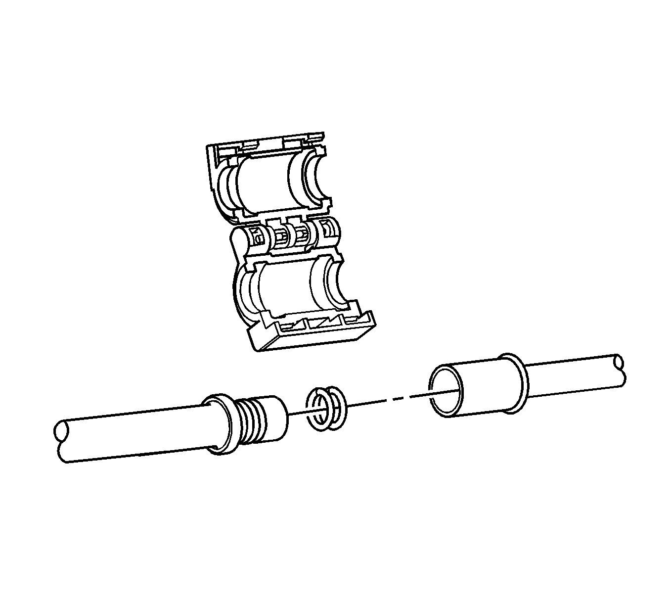
- Disconnect and remove the A/C tube connectors from the evaporator rear line assembly. Refer to Air Conditioning Line/Tube Connector Removal/Replacement.
- Disconnect the front evaporator inlet line from the evaporator rear line assembly.
- Remove and discard O-rings.
- Cap or tape the front evaporator inlet line.
- Disconnect the A/C compressor line from the evaporator rear line assembly.
- Remove and discard the O-rings.
- Cap or tape the front evaporator line and A/C compressor line.
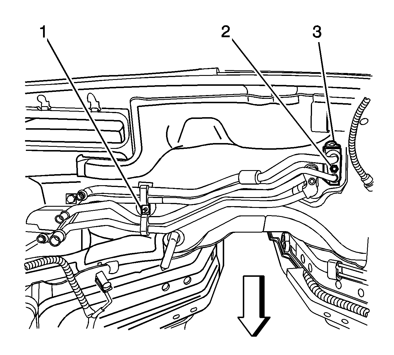
- Remove the heater pipe bracket retaining nut (1) from the cowl stud.
- Remove the thermal expansion valve (TXV) block fitting nut (2).
- Disconnect the evaporator rear line assembly from the TXV (3).
- Disconnect the evaporator rear line assembly from the retainer bracket stud.
- Remove the rear evaporator line assembly from the vehicle.
- Remove and discard the seal washers.
- Cap or tape the TXV (3).


Note: Immediately cap or tape the open A/C components in order to prevent contamination.

Installation Procedure
- Remove the cap or tape from the TXV (3).
- Install new seal washers to the evaporator rear line assembly. Refer to Sealing Washer Replacement.
- Install the evaporator rear line assembly to the vehicle.
- Connect the evaporator rear line assembly to the retainer bracket stud.
- Connect the evaporator rear line assembly to the TXV (3).
- Install the TXV block fitting nut (2) and tighten to 20 N·m (15 lb ft).
- Install the heater pipe bracket retaining nut (1) to the cowl stud and tighten to 10 N·m (89 lb in).
- Remove cap or tape from the front evaporator line and A/C compressor line.
- Install new O-rings to the rear evaporator line assembly. Refer to O-Ring Replacement.
- Connect the A/C compressor line to the evaporator rear line assembly.
- Connect the front evaporator line to the evaporator rear line assembly.
- Connect the A/C tube connectors onto the evaporator rear line assembly. Refer to Air Conditioning Line/Tube Connector Removal/Replacement.
- Connect the refrigerant pressure sensor electrical connector.
- Connect the front evaporator inlet line to the body retaining clip.
- Install the intake manifold. Refer to Intake Manifold Replacement.
- Install the battery. Refer to Battery Replacement.
- Evacuate and recharge the A/C system. Refer to Refrigerant Recovery and Recharging.
- Leak test the fittings of the component using J 39400-A Halogen Leak Detector .

Note: If replacing the evaporator rear line assembly, add the specified amount of polyalkylene glycol (PAG) oil directly to the evaporator rear line assembly. Refer to Refrigerant System Capacities.
Caution: Refer to Fastener Caution in the Preface section.


