Steering Shaft, Lower Bearing, and Jacket Replacement Telescoping
Special Tools
J 21854-01 Pivot Pin Remover
Removal Procedure
- Disable the SIR system. Refer to SIR Disabling and Enabling.
- Remove the signal switch housing. Refer to Steering Column Tilt Head Housing Replacement.
- Remove the tilt spring only. Refer to Steering Column Tilt Spring Replacement.
- Remove the telescoping actuator assembly. Refer to Telescope Actuator Assembly Replacement.
- Remove the telescoping motor assembly. Refer to Telescope Motor Assembly Replacement.
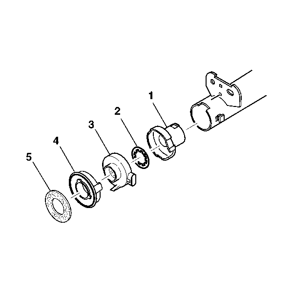
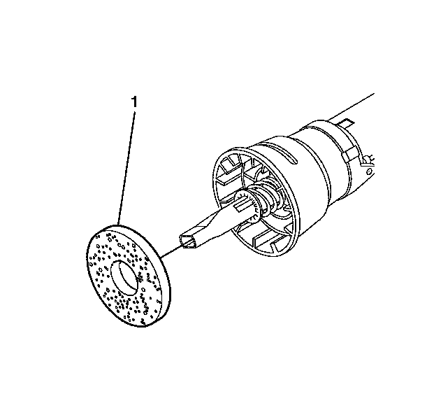
- Remove the steering shaft seal (5).
- Remove the sensor retainer (4).
- Remove the sensor assembly (3).
- Remove the lower spring retainer (2).
- Remove the adapter and bearing assembly (1).
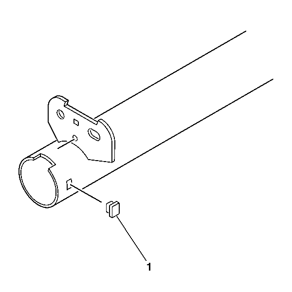
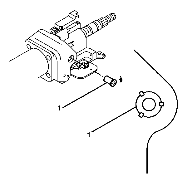
- Remove the jacket hole plug (1).
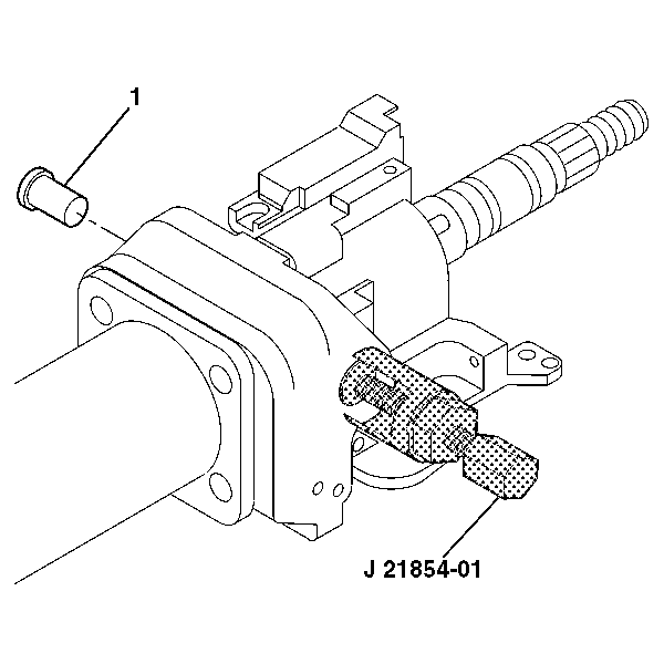
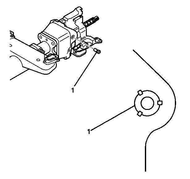
- Remove the 2 pivot pins (1) from the steering column support assembly using J 21854-01 .
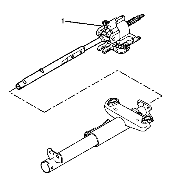
- Disengage the steering column lock shoes from the dowel pins in the steering column tilt head housing assembly (1).
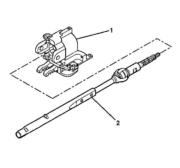
- Remove the steering column tilt head housing assembly (1) with the steering shaft assembly from the jacket assembly.
- Remove the steering shaft assembly (2) from the steering column tilt head housing assembly (1).
- Mark the race and upper shaft assembly.
- Mark the lower steering shaft assembly.
- Tilt the race and upper shaft assembly 90 degrees to the lower steering shaft assembly to disengage.
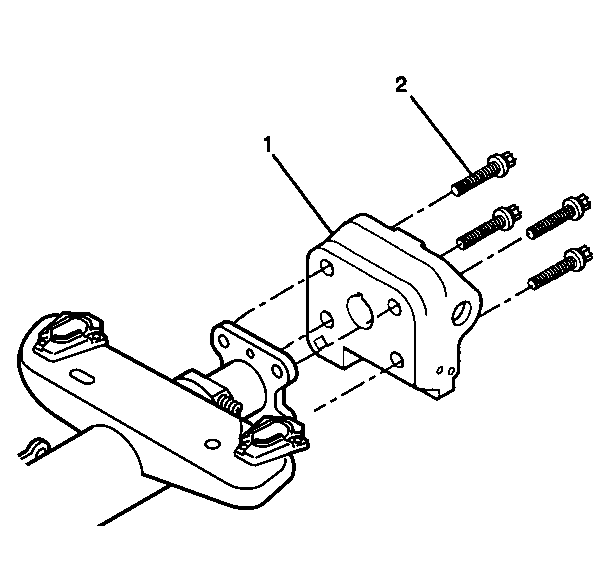
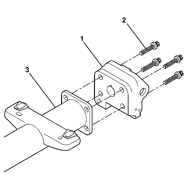
- Remove the 4 TORX® head screws (2).
- Remove the steering column support assembly (1) from the jacket assembly.
Warning: Refer to SIR Warning in the Preface section.
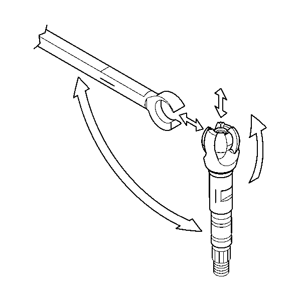
Note: Carefully mark the parts to ensure proper assembly. Failure to assemble properly will cause the steering wheel to be turned 180 degrees.
Installation Procedure
- Install the steering column support assembly (1) to the jacket assembly.
- Install the 4 TORX® screws (2).
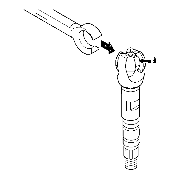
- Apply GM P/N 12345718 (Canadian P/N 10953516) to the exposed shaft engagement areas on the centering sphere.
- Install the lower steering shaft assembly to the race and upper shaft assembly to engage.
- Install the steering shaft assembly (2) into the steering column tilt head housing assembly (1).
- Install the steering column tilt head housing assembly (1) and the steering shaft assembly to the jacket assembly.
- Install the 2 pivot pins (1) to the steering column support assembly.
- Stake the pivot pins locations (1).
- Install the adapter and bearing assembly (1) to the steering shaft assembly.
- Install the lower spring retainer (2) to the adapter and bearing assembly (1).
- Install the sensor assembly (3) onto the steering shaft assembly.
- Install the steering shaft seal (1).
- Install the telescope actuator assembly. Refer to Telescope Actuator Assembly Replacement.
- Install the telescope motor assembly. Refer to Telescope Motor Assembly Replacement.
- Install the tilt spring only. Refer to Steering Column Tilt Spring Replacement.
- Install the signal switch housing. Refer to Steering Column Tilt Head Housing Replacement.
- Enable the SIR system. Refer to SIR Disabling and Enabling.

Note: Replace the steering column support assembly if the steering column support assembly has been staked 3 times.
Caution: Refer to Fastener Caution in the Preface section.
Tighten
Tighten the screws to 18 N·m (13 lb ft).


Note: Replace the steering column support assembly if the steering column support assembly has been staked 3 times.

Note: Rotate the steering shaft assembly to the 12 o'clock position.
Install the sensor retainer (4) and seal (5) onto the steering shaft assembly.
Warning: Refer to SIR Inflator Module Coil Warning in the Preface section.
Steering Shaft, Lower Bearing, and Jacket Replacement Manual
Special Tools
J 21854-01 Pivot Pin Remover
Removal Procedure
- Disable the SIR system. Refer to SIR Disabling and Enabling.
- Remove the wiper/washer switch bracket. Refer to Steering Column Tilt Head Housing Replacement.
- Remove the tilt spring. Refer to Steering Column Tilt Spring Replacement.
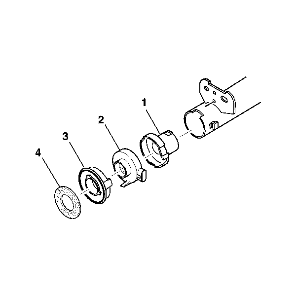
- Remove the steering shaft seal (4).
- Remove the sensor retainer (3).
- Remove the sensor assembly (2).
- Remove the adapter and bearing assembly (1).
- Remove the 2 pivot pins (1) from the steering column support assembly using J 21854-01 .
- Install the tilt lever.
- Pull the tilt lever to disengage the steering column lock shoes from the dowel pins in the steering column tilt head housing assembly.
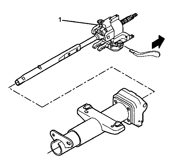
- Remove the steering column tilt head housing assembly (1) with the steering shaft assembly from the steering column jacket assembly.
- Remove the steering shaft assembly (2) from the steering column tilt head housing assembly (1).
- Mark the race and upper shaft assembly.
- Mark the lower steering shaft assembly.
- Tilt the race and upper shaft assembly 90 degrees to the lower steering shaft assembly to disengage.
- Remove the 4 TORX® head screws (2).
- Remove the steering column support assembly (1) from the steering column jacket assembly (3).
Warning: Refer to SIR Warning in the Preface section.



Note: Carefully mark the parts to ensure proper assembly. Failure to assemble properly will cause the steering wheel to be turned 180 degrees.
Installation Procedure
- Install the steering column support assembly (1) to the steering column jacket assembly (3).
- Install the 4 TORX® head screws (2).
- Apply GM P/N 12345718 (Canadian P/N 10953516) to the exposed shaft engagement areas on the centering sphere.
- Install the lower steering shaft assembly to the race and upper shaft assembly to engage.
- Install the steering shaft assembly (2) into the steering column tilt head housing assembly (1).
- Install the steering column tilt head housing assembly (1) and the steering shaft assembly to the steering column jacket assembly.
- Install the 2 pivot pins (1) to the steering column support assembly.
- Stake the pivot pins locations (1).
- Install the adapter and bearing assembly (1) to the steering shaft assembly.
- Install the sensor assembly (2) onto the steering shaft assembly.
- Install the sensor retainer (3) onto the steering shaft assembly.
- Install the steering shaft seal (4).
- Install the wiper/washer switch bracket. Refer to Steering Column Tilt Head Housing Replacement.
- Install the tilt spring. Refer to Steering Column Tilt Spring Replacement.
- Enable the SIR system. Refer to SIR Disabling and Enabling.

Note: Replace the steering column support assembly if the steering column support assembly has been staked 3 times.
Caution: Refer to Fastener Caution in the Preface section.
Tighten
Tighten the screws to 18 N·m (13 lb ft).


Note: Replace the steering column support assembly if the steering column support assembly has been staked 3 times.

Note: The steering shaft assembly must be rotated to the 12 o'clock position.
