For 1990-2009 cars only
Special Tools
J-42188-B Ball Joint Separator
Removal Procedure
- Raise and support the vehicle. Refer to Lifting and Jacking the Vehicle.
- Remove the brake caliper and rotor. Refer to Front Brake Rotor Replacement and Front Brake Caliper Replacement.
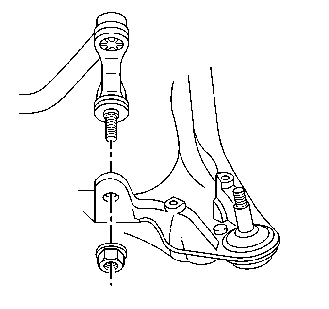
- Remove the stabilizer shaft link from the lower control arm.
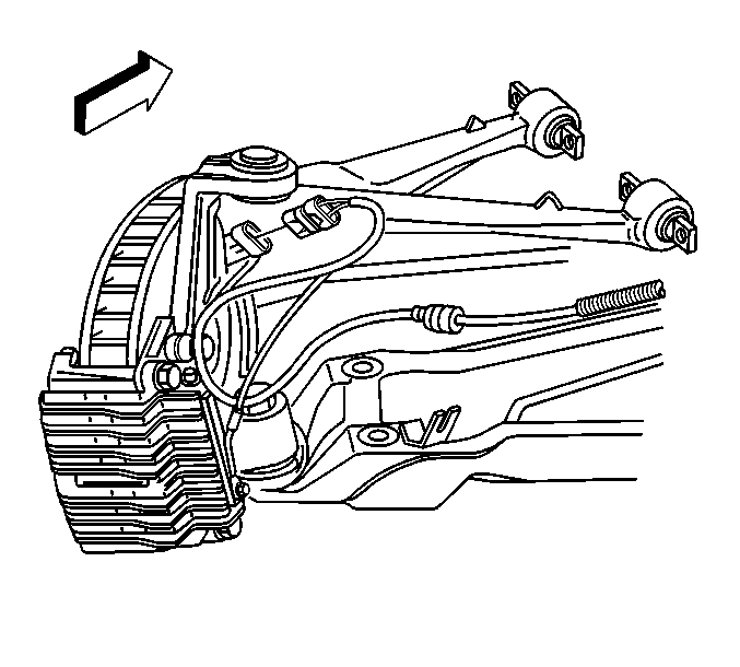
- Disconnect the wheel speed sensor electrical connector.
- Support the lower control arm using a jackstand.
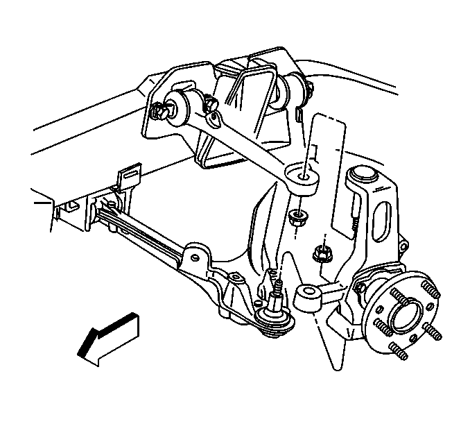
- Separate the steering linkage outer tie rod ball stud from the steering knuckle using J 42188 . Refer to Steering Linkage Outer Tie Rod Replacement.
- Separate and remove the upper control arm ball joint stud from the steering knuckle using J 42188 . Refer to Upper Control Arm Replacement.
- Using J 42188 separate and remove the lower ball joint stud from the steering knuckle. Refer to Lower Control Arm Replacement.
- Remove the steering knuckle from the vehicle.


Installation Procedure
- Install steering knuckle to the upper control arm and the lower control arm. Refer to Upper Control Arm Replacement and Lower Control Arm Replacement.
- Remove the jackstand.
- Install the steering linkage outer tie rod ball stud to the steering knuckle. Refer to Steering Linkage Outer Tie Rod Replacement.
- Install the stabilizer shaft link to the lower control arm.
- Connect the wheel speed sensor electrical connector.
- Install the brake rotor and caliper. Refer to Front Brake Rotor Replacement and Front Brake Caliper Replacement.
- Install the tire and wheel assembly. Refer to Tire and Wheel Removal and Installation.
- Lower the vehicle.
- Check the front wheel toe and adjust as necessary. Refer to Diagnostic Starting Point - Disc Brakes Wheel Alignment Measurement.

Caution: Refer to Fastener Caution in the Preface section.
Tighten
Tighten the stabilizer shaft link nut to 72 N·m (53 lb ft).

