For 1990-2009 cars only
Removal Procedure
- Remove the Fuel Sender Assembly. Refer to Fuel Sender Assembly Replacement .
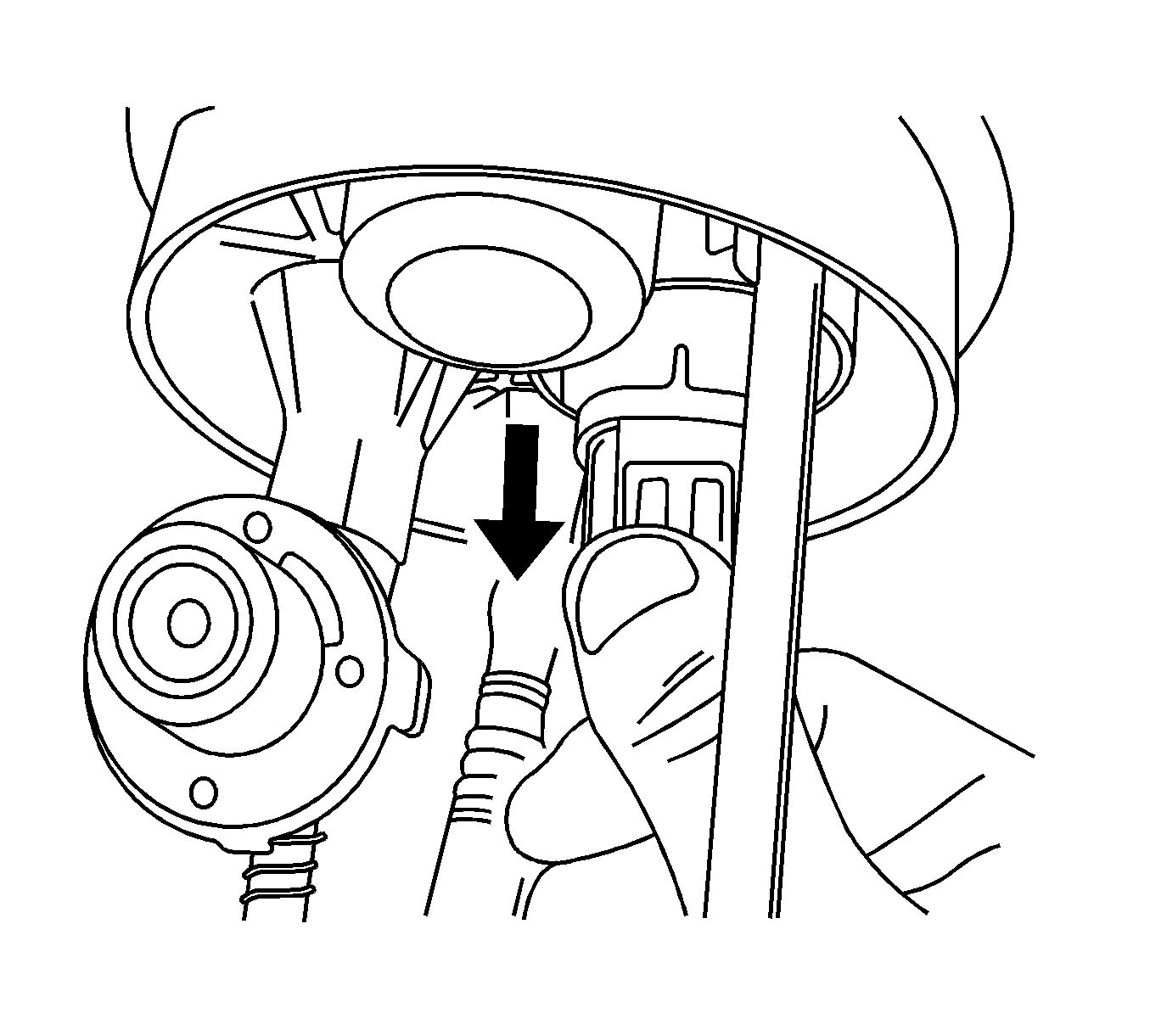
- Disconnect the insulator connector.
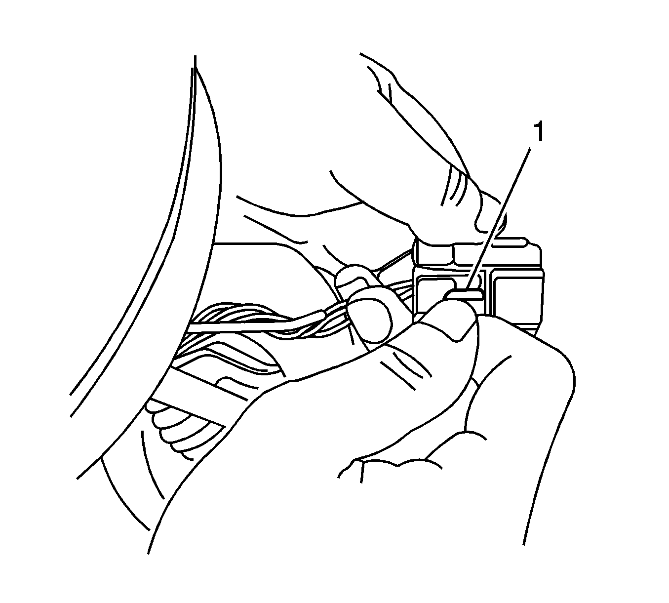
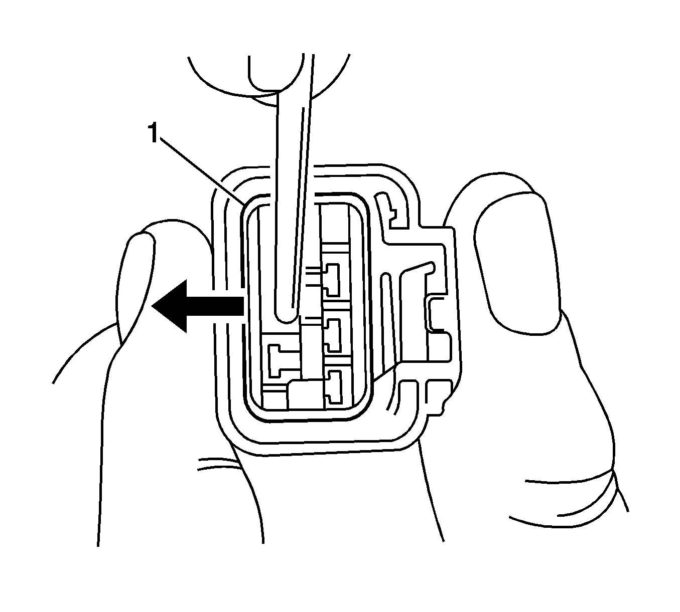
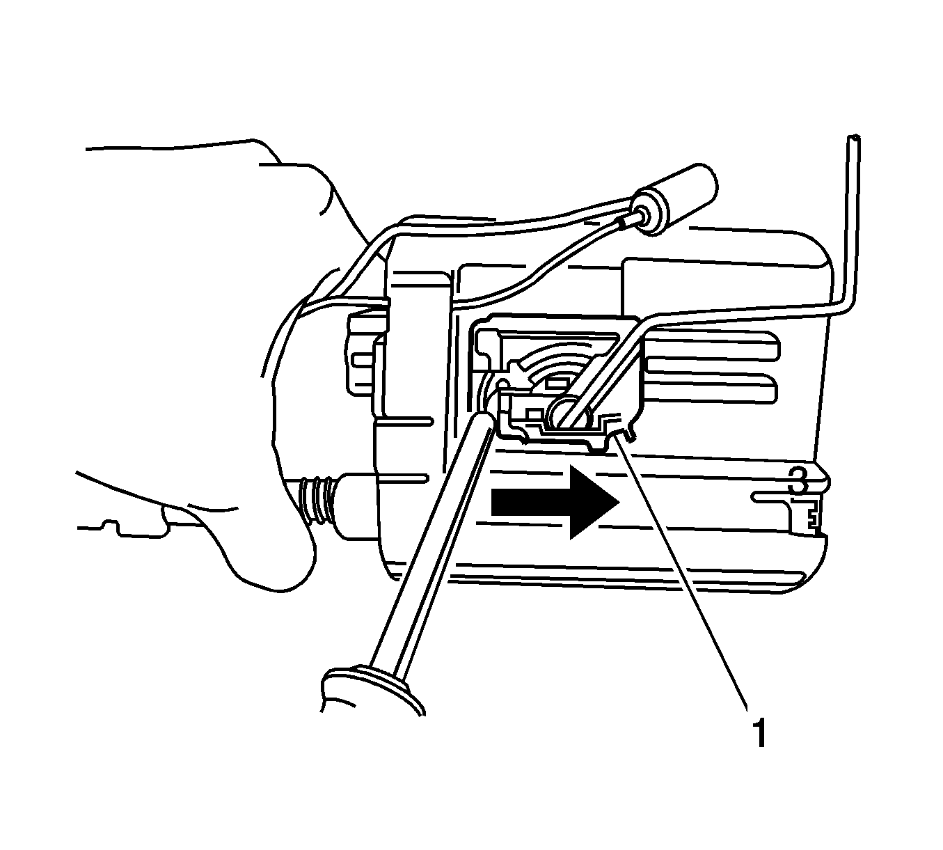
- Push the terminal wedge (1) in the insulator connector.
- Push the wedge (1) outside and then pull the wires to disconnect from the insulator.
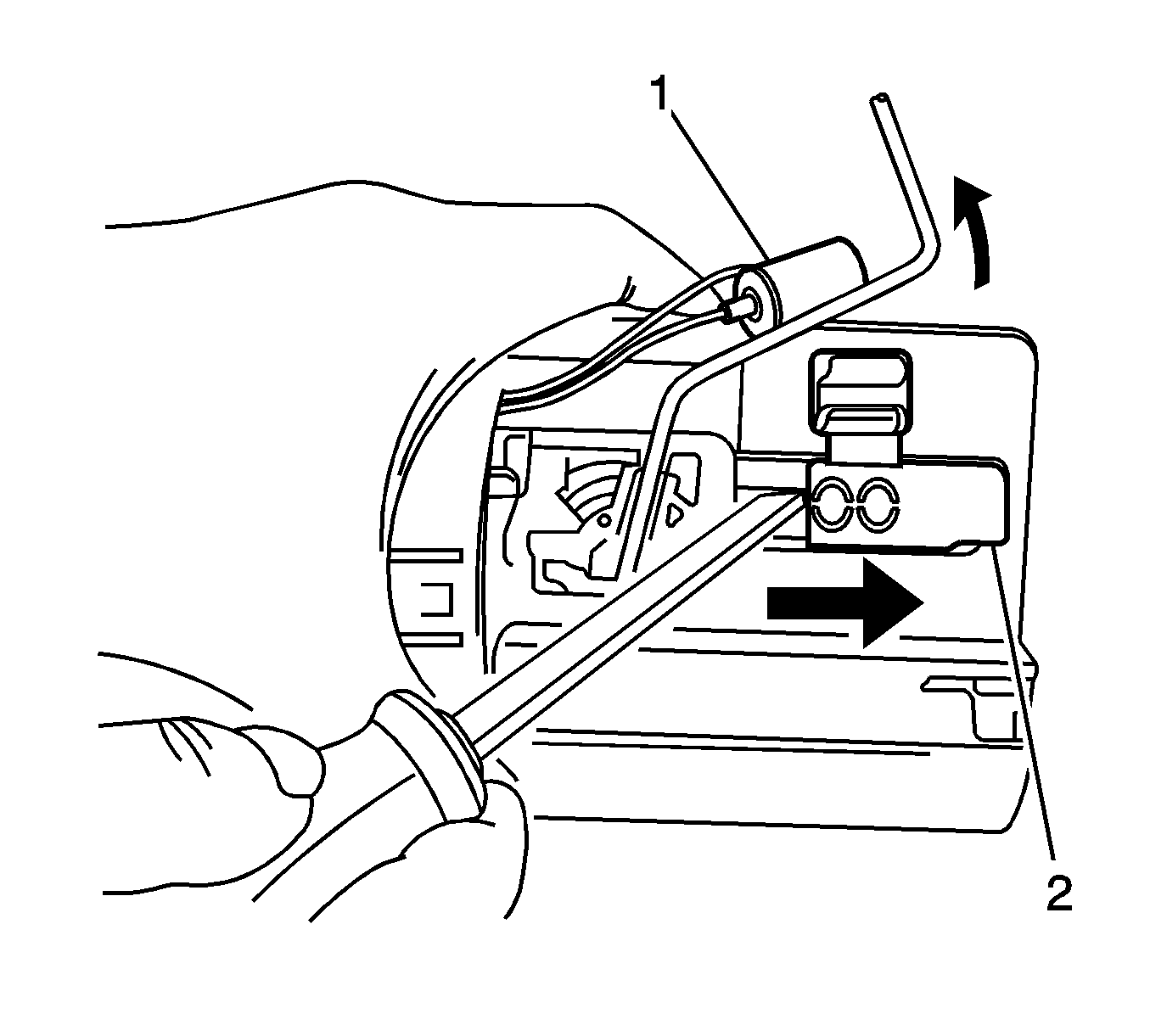
- Remove the fuel level sensor (1) from the sender housing (2).
- Remove the sender housing (2).
- Remove the fuel level sensor (1).
Caution: Refer to Relieving Fuel Pressure Caution in the Preface section.
Installation Procedure
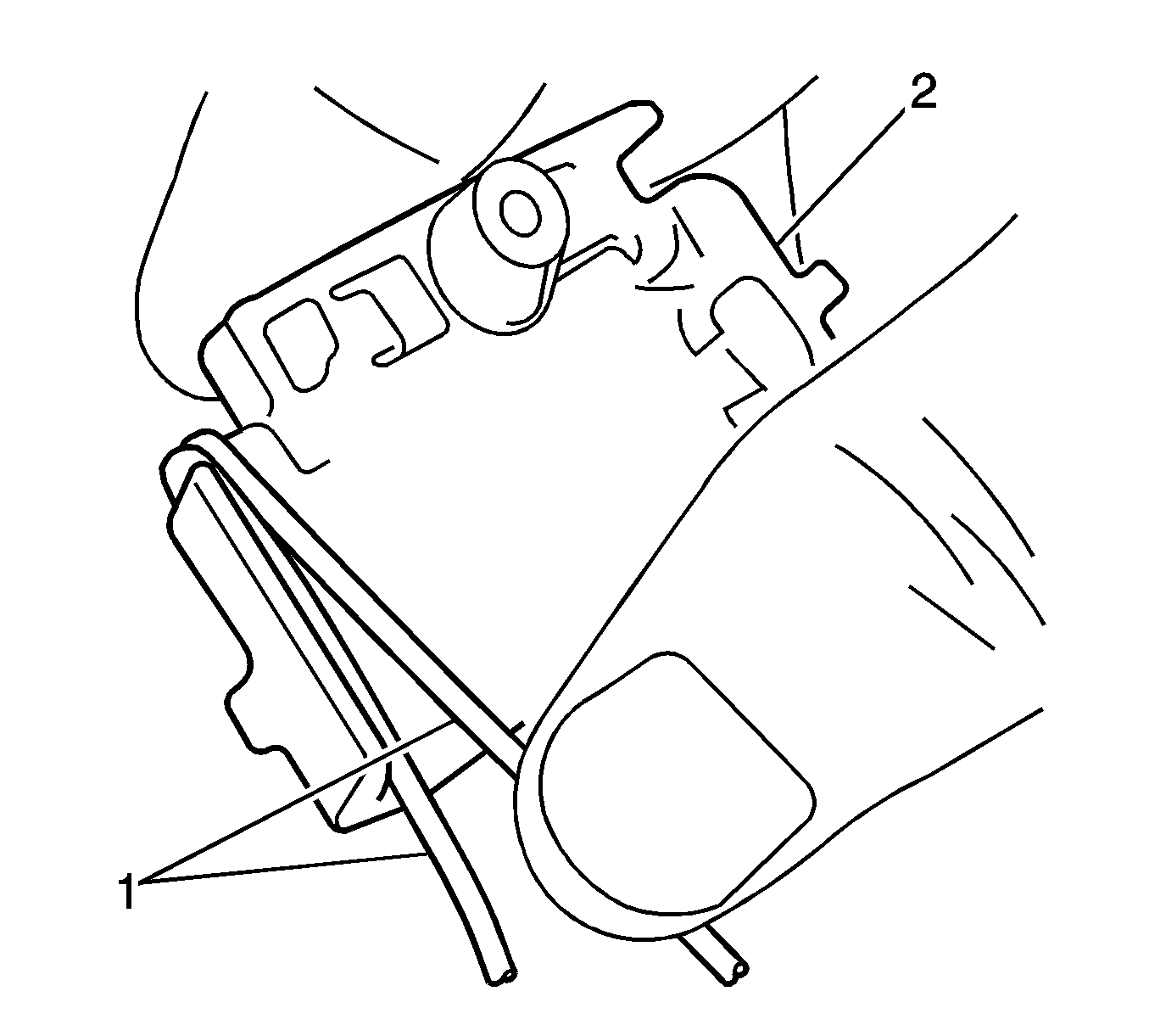
- Wind the wires (1) to the fuel level sensor (2).
- Install the fuel level sensor onto the fuel sender assembly (1).
- Connect the wires into the insulator connector as follows:
- Connect the insulator connector.
- Install the fuel sender assembly. Refer to Fuel Sender Assembly Replacement .
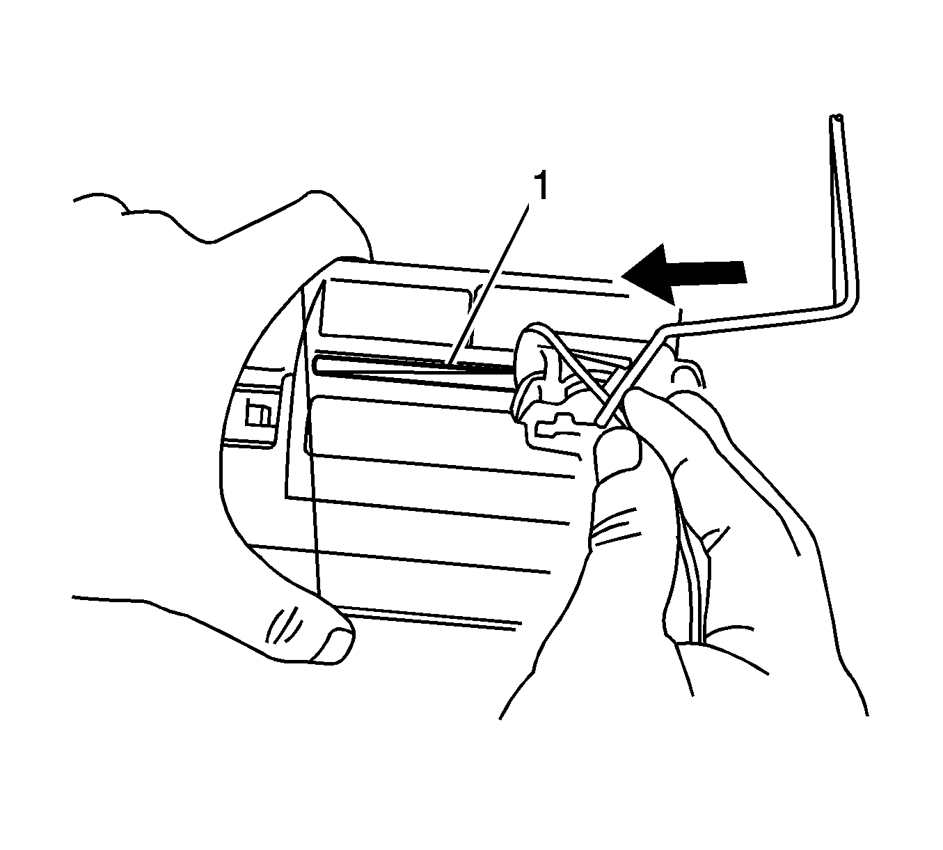
Important: Failure to install the fuel level sensor correctly will result in inaccurate fuel gage reading.
Important: Failure to install the fuel level sensor correctly will result in inaccurate fuel level warning lamp operation.
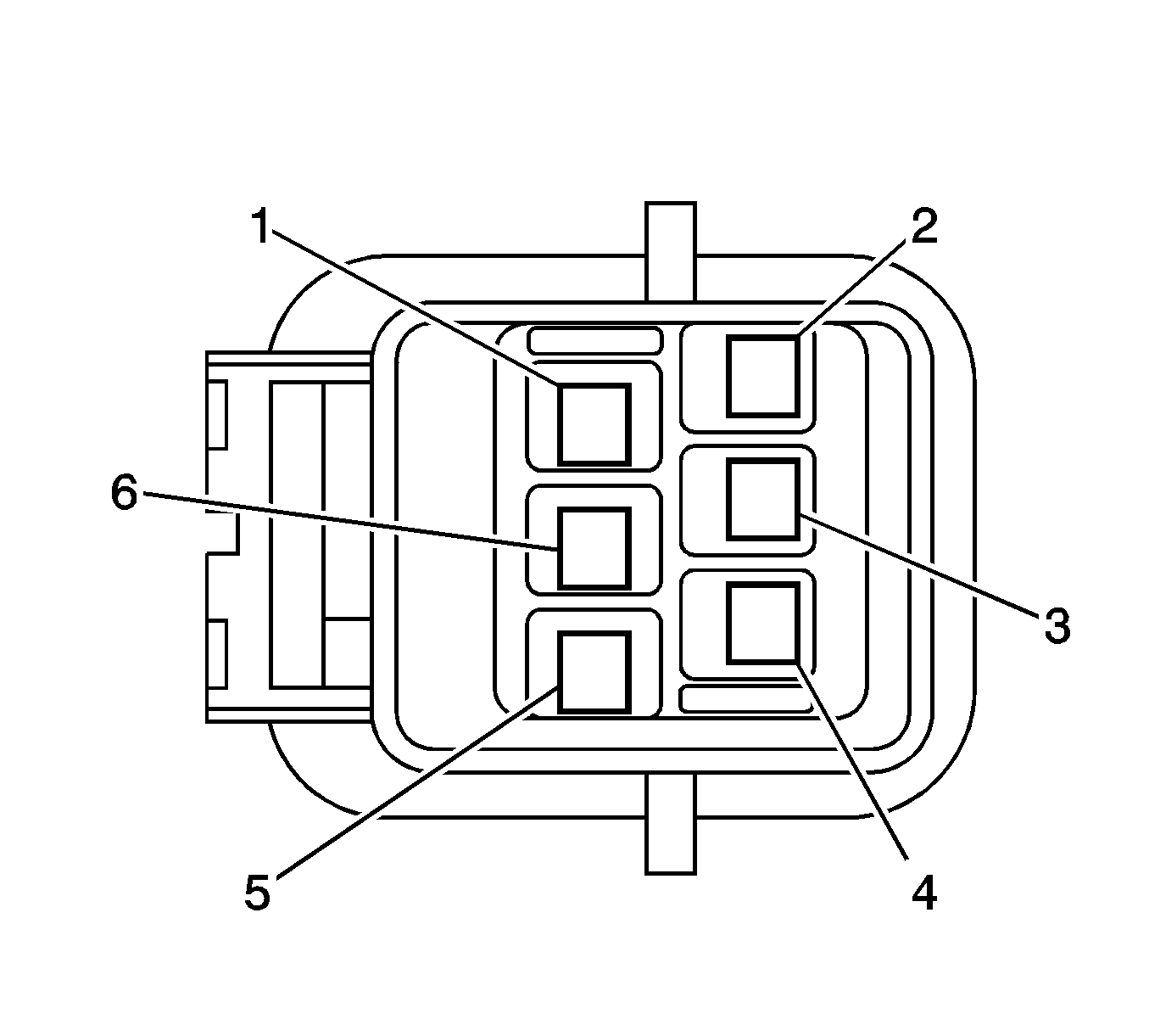
| • | Connect wire (1), Red |
| • | Connect wire (2), Blue |
| • | Connect wire (3), Gray |
| • | Connect wire (4), Yellow |
| • | Connect wire (5), Blue |
| • | Connect wire (6), Black |

