Transmission Replacement 2.0L DOHC
Tools Required
| • | J 28467-B (DW117) Universal Engine Support Fixture |
| • | DW 260-010 (DW260-010) Auto Transaxle Support Fixture |
Removal Procedure
- Disconnect the negative battery cable.
- Position the select lever in the PARK position.
- Remove the battery. Refer to Battery and Battery Tray Replacement in Engine Electrical.
- Remove the air filter housing.
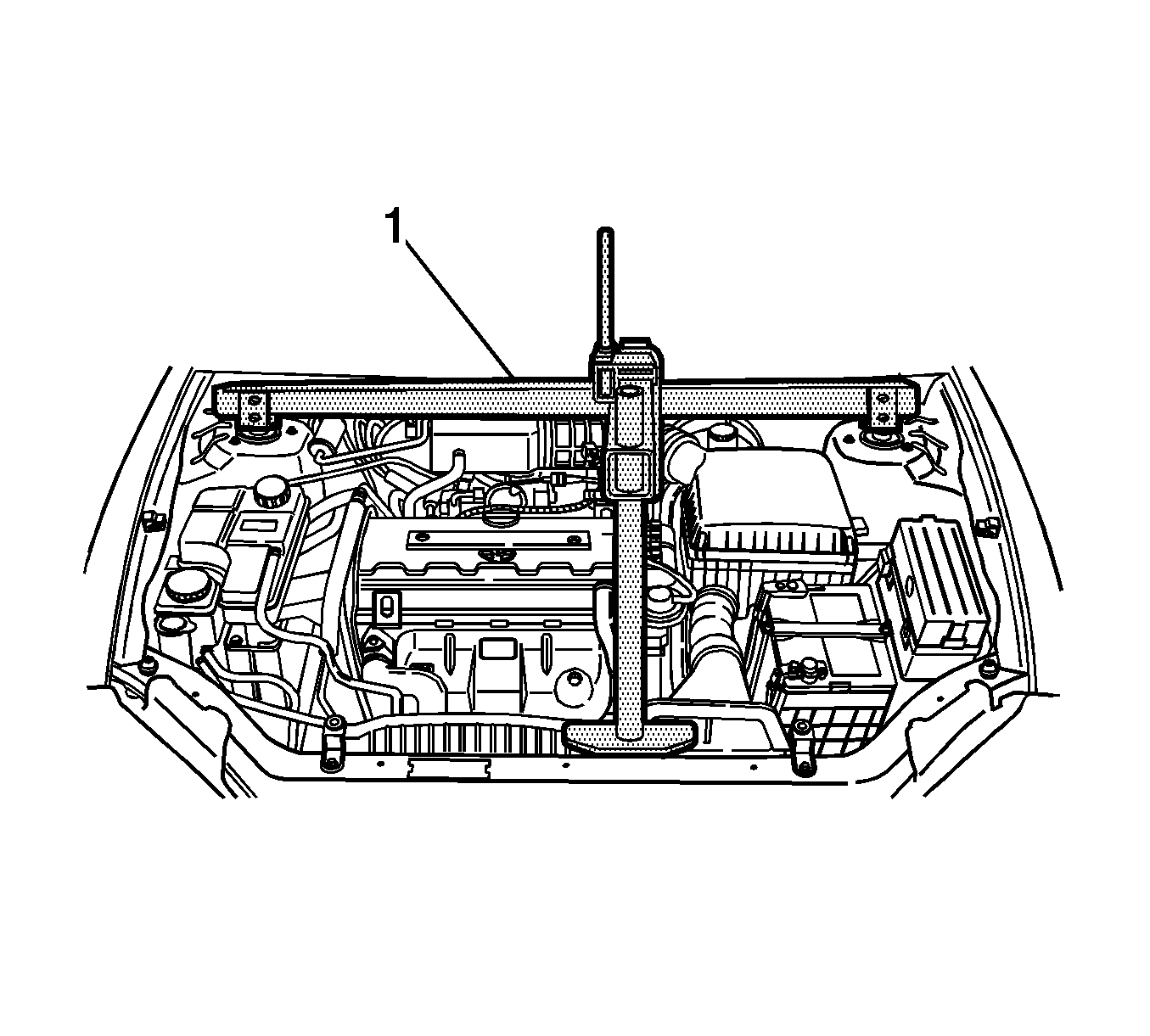
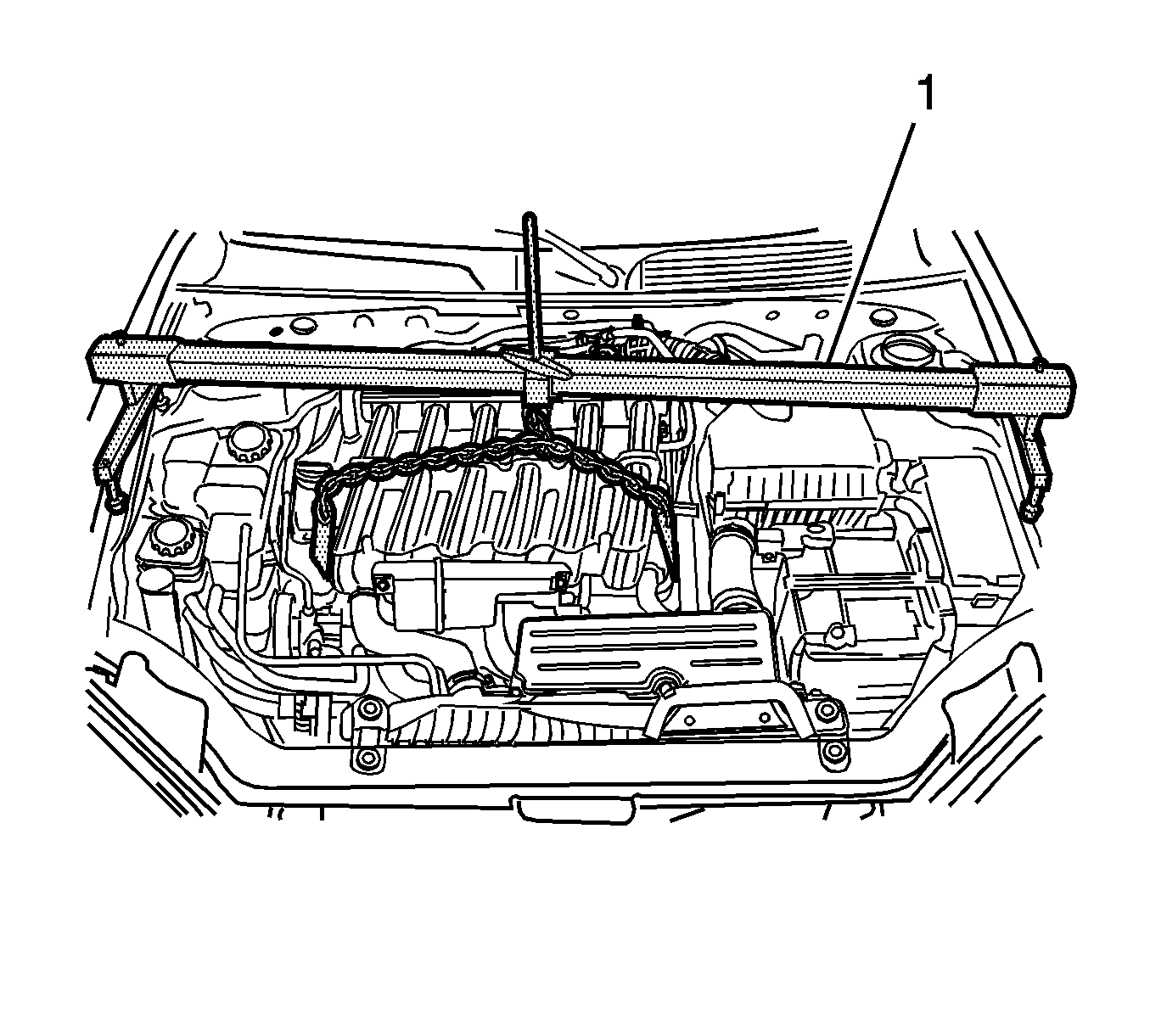
- Install the J 28467-B (1) .
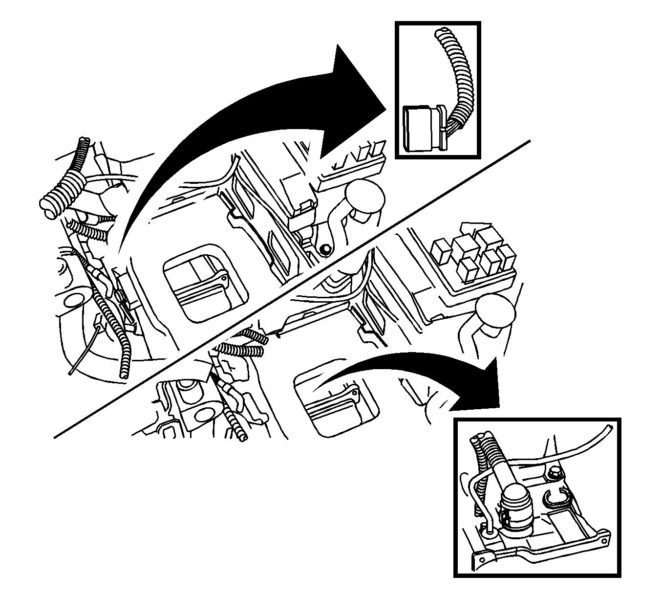
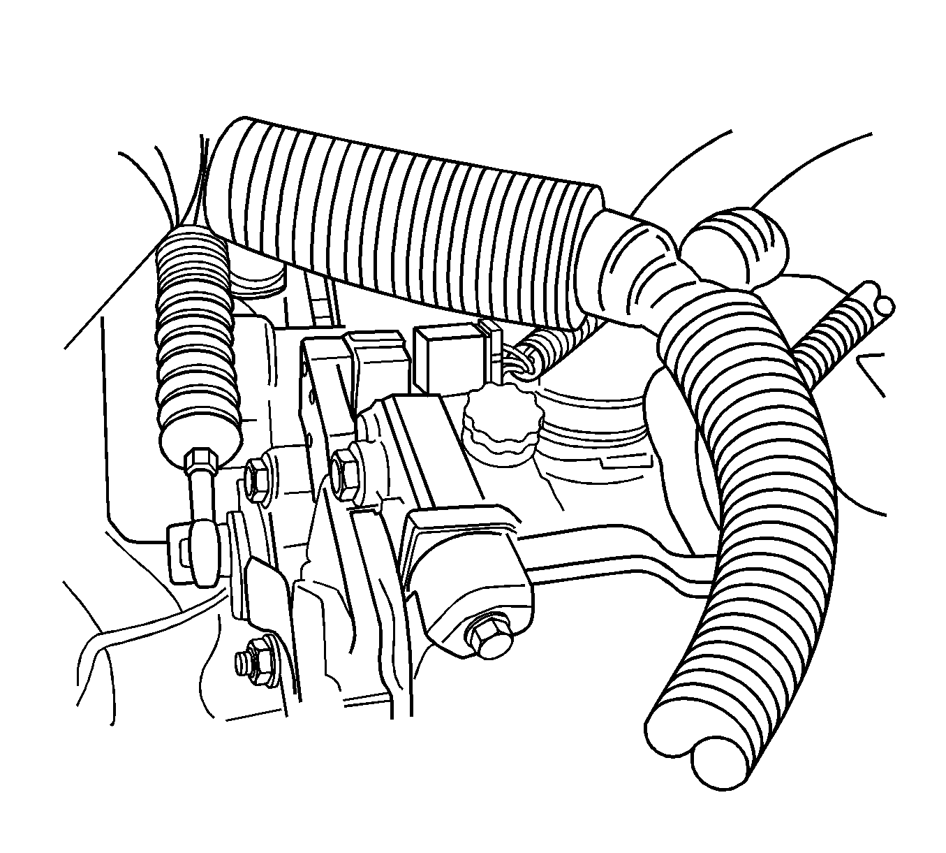
- Disconnect the transaxle wiring harness from the transaxle
- Disconnect the park/neutral position switch electrical connector.
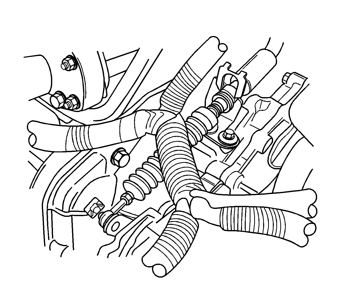
- Remove the clips from the shift control cable. Disconnect the shift control cable from the transaxle.
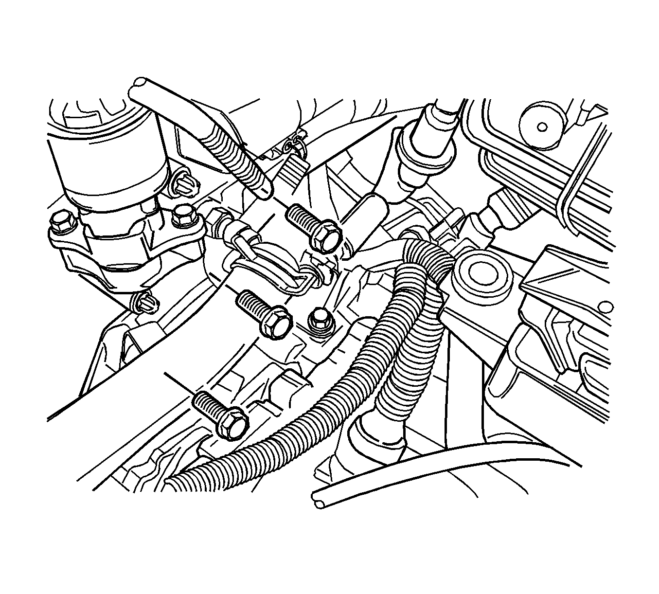
- Remove the upper transaxle-to-engine bolts.
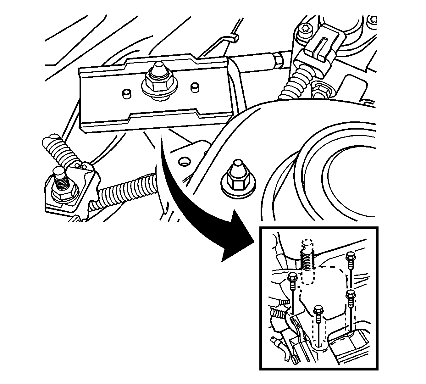
- Remove the left transaxle mounting bracket. Refer to Transmission Mount Bracket Replacement .
- Raise and suitably support the vehicle.
- Remove the front engine crossbar. Refer to Engine Front Crossmember Replacement in Front Suspension.
- Remove the impact bar. Refer to I-Beam Suspension Replacement in Front Suspension.
- Drain the transaxle fluid.
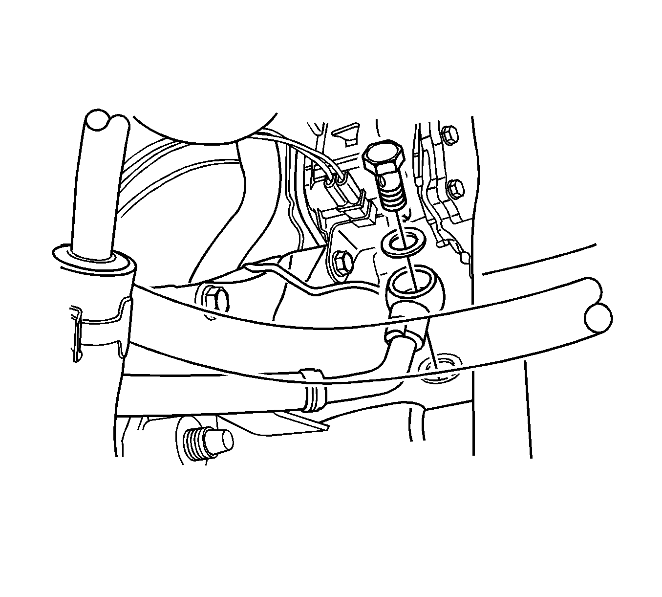
- Remove the oil cooler pipes from the transaxle. Refer to Transmission Fluid Cooler Hose/Pipe Replacement
- Remove the drive axle. Refer to Front Drive Axle Inner Shaft Replacement in front Drive Axle.
- Remove the starter motor. Refer to Starter Motor Replacement in Engine Electrical.
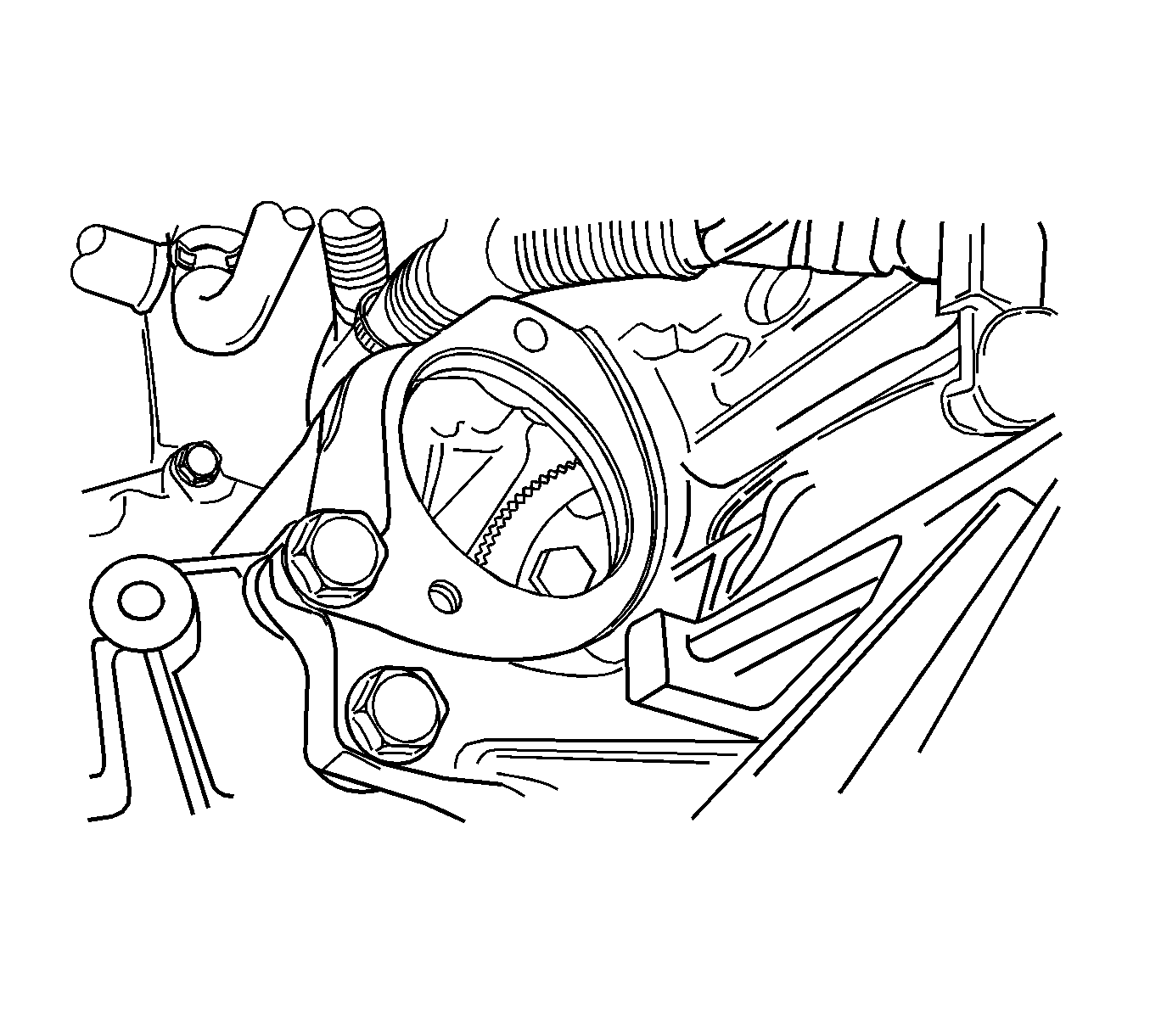
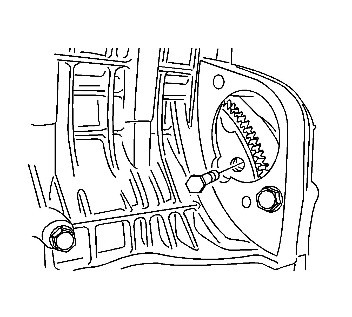
- Remove the flywheel to torque converter bolts.
- Support the transaxle.
- Remove the front catalytic converter retaining nuts. Refer to Catalytic Converter Replacement in Engine Exhaust.
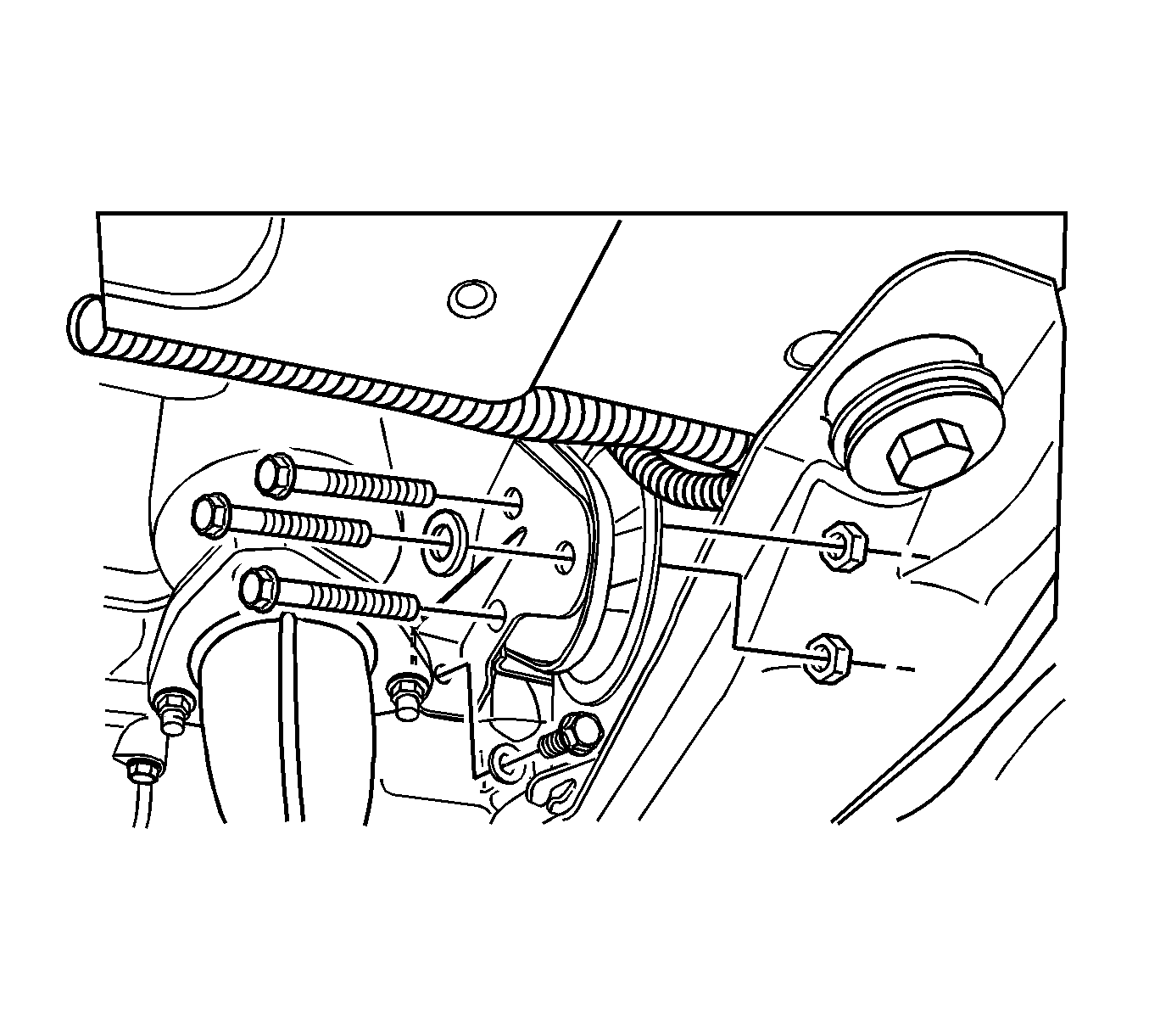
- Remove the front engine mounting bracket bolts and nuts.
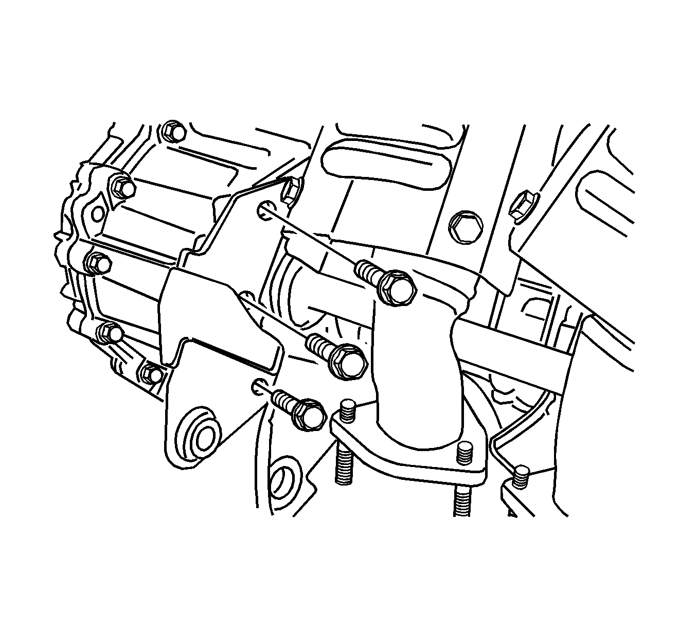
- Remove the rear transaxle mounting bracket bolts.
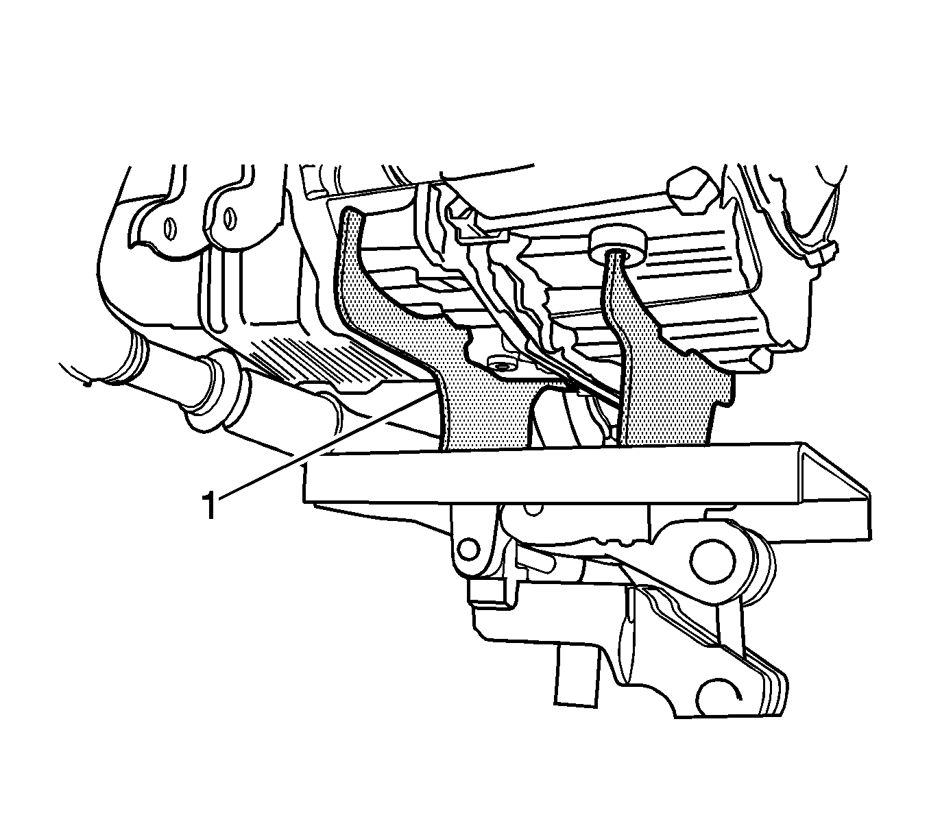
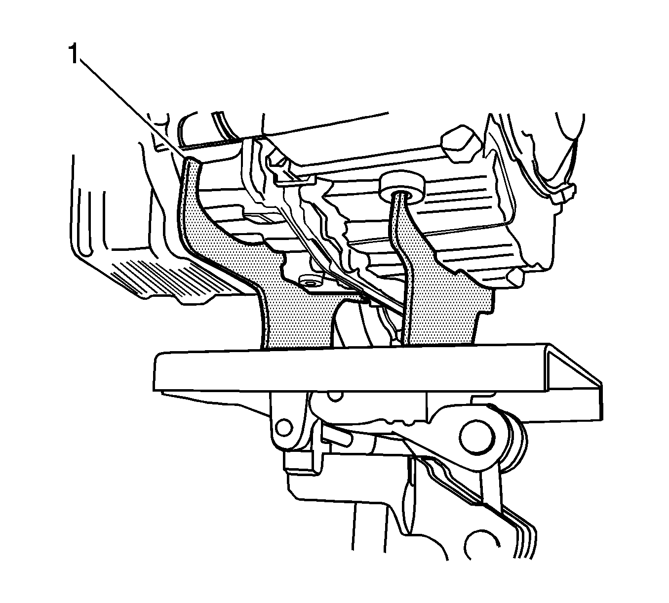
- Using the DW 260-010 (1) or equivalent to support the transaxle assembly
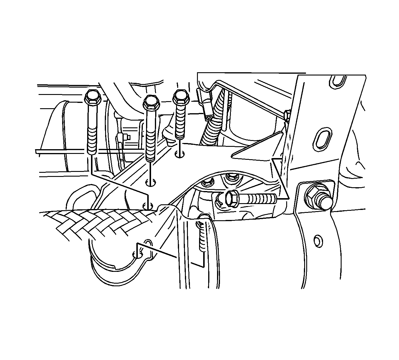
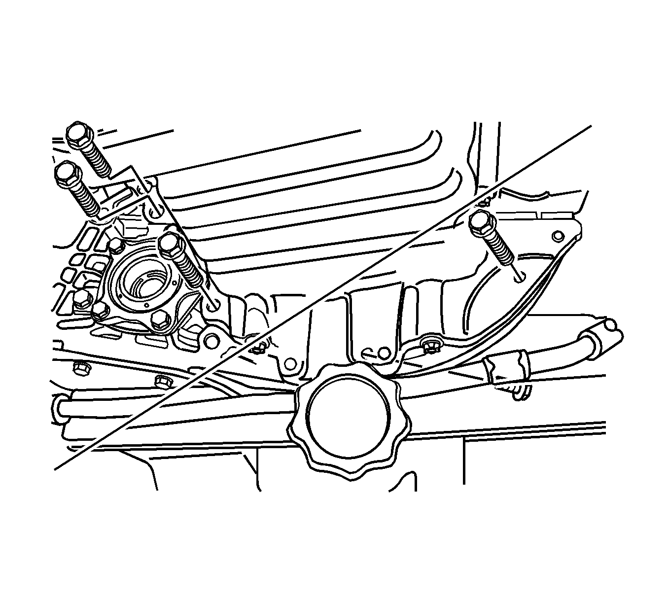
- Remove the lower engine-to-transaxle bolts.
- Use the DW 260-010 (1) or equivalent to remove the transaxle assembly.
Caution: Refer to Battery Disconnect Caution in the Preface section.
Notice: Refer to Vehicle Lifting and Jacking Notice in the Preface section.

Installation Procedure
- Install the transaxle into the vehicle.
- Use the DW 260-010 (1) or equivalent to support the transaxle assembly .
- Install the lower engine-to-transaxle bolts.
- Install the rear transaxle mounting bracket bolts.
- Install the front engine mounting bracket bolts and nuts.
- Install the front catalytic converter retaining nuts. Refer to Catalytic Converter Replacement in Engine Exhaust.
- Install the flywheel to torque converter bolts.
- Install the starter motor. Refer to Starter Motor Replacement in Engine Electrical.
- Install the drive axle. Refer to Front Drive Axle Inner Shaft Replacement in Front Drive Axle.
- Install the oil cooler pipes from the transaxle. Refer to Transmission Fluid Cooler Hose/Pipe Replacement .
- Install the impact bar. Refer to I-Beam Suspension Replacement in Front Suspension.
- Install the front engine cross-member. Refer to Engine Front Crossmember Replacement in Front Suspension.
- Lower the vehicle.
- Install the left transaxle mounting bracket. Refer to Transmission Mount Bracket Replacement .
- Install the upper transaxle-to-engine bolts.
- Install the clips to the shift control cable. Connect the shift cable.
- Install the park/neutral position switch electrical connector.
- Connect the transaxle wiring harness to the transaxle.
- Remove the J 28467-B (1) .
- Install the air filter housing.
- Install the battery. Refer to Battery and Battery Tray Replacement in Engine Electrical.
- Add the transaxle fluid. Refer to Transmission Fluid Level Inspection .
- Connect the negative battery cable.
Important: After installing the transmission assembly, the shift adapts must be reset. reset the shift adapts using the scan tool. Go to "Trans Adaptives Reset" under "Special Functions" on the scan tool.

Notice: Refer to Fastener Notice in the Preface section.
Tighten
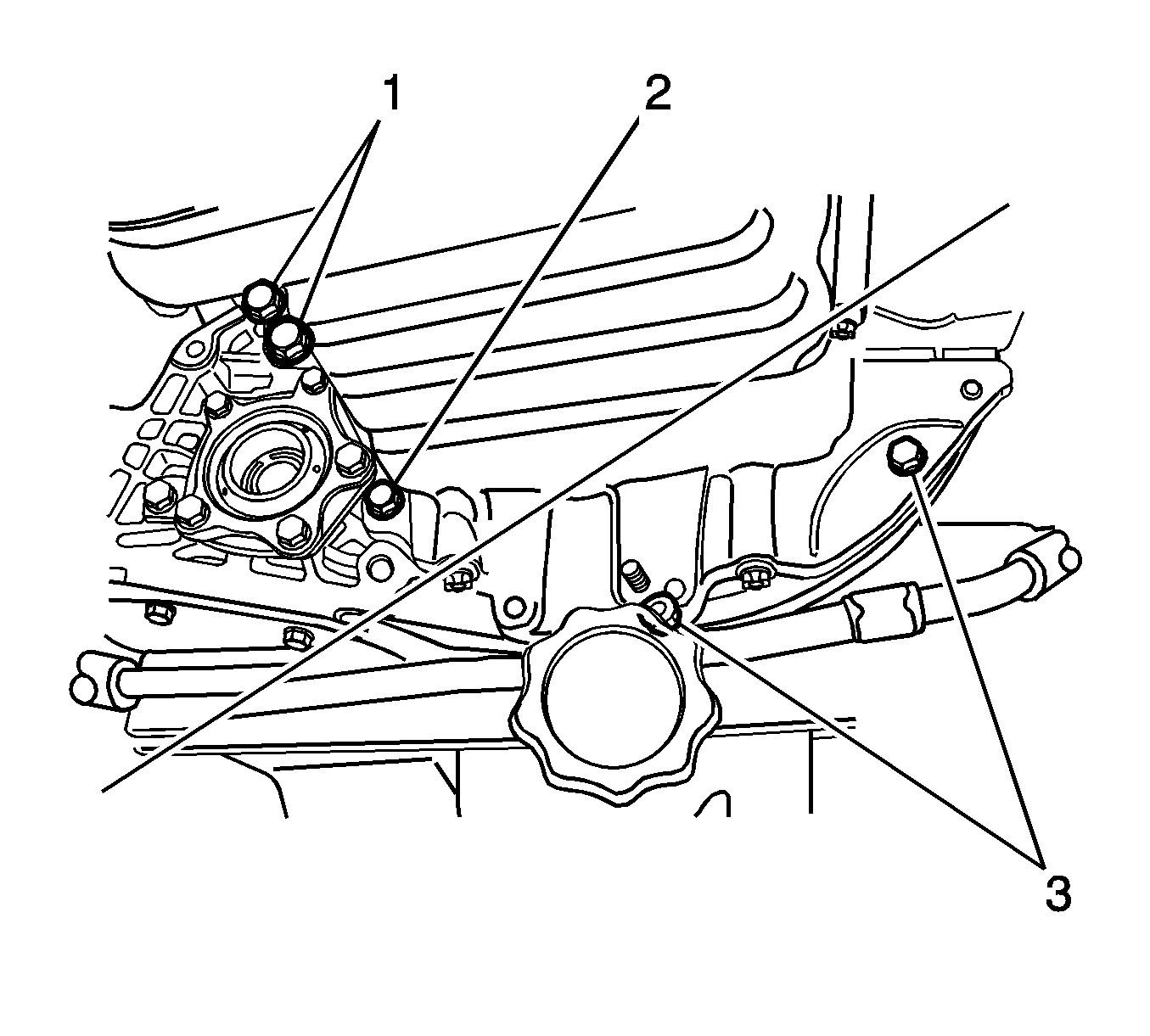
| • | Tighten the lower engine-to-transaxle bolts (1) to 75 N·m (55 lb ft). |
| • | Tighten the lower engine-to-transaxle bolts (2) to 21 N·m (15 lb ft). |
| • | Tighten the lower engine-to-transaxle bolts (3) to 31 N·m (23 lb ft). |
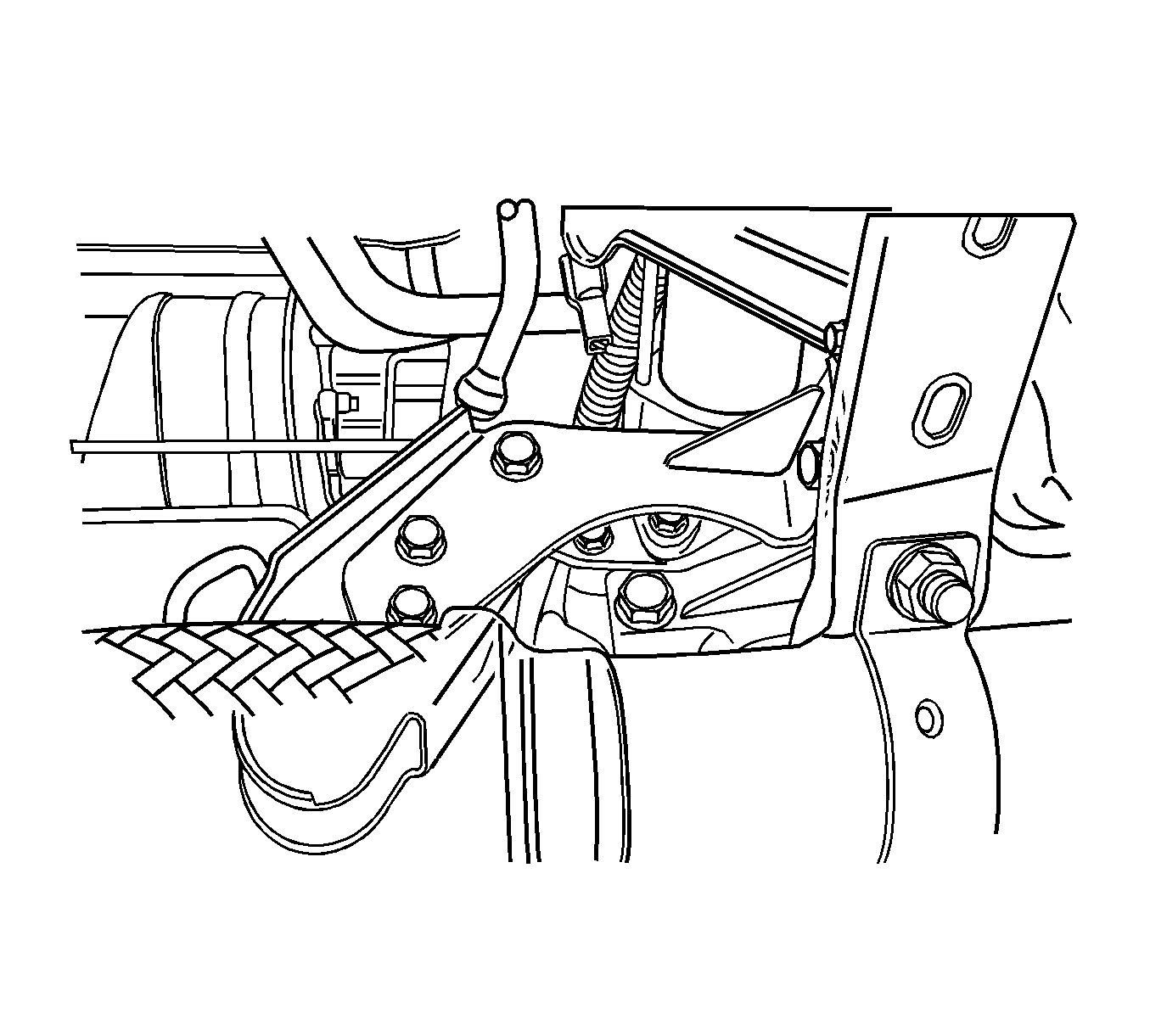
Tighten
Tighten the rear transaxle mounting bracket bolts to 65 N·m (48 lb ft).
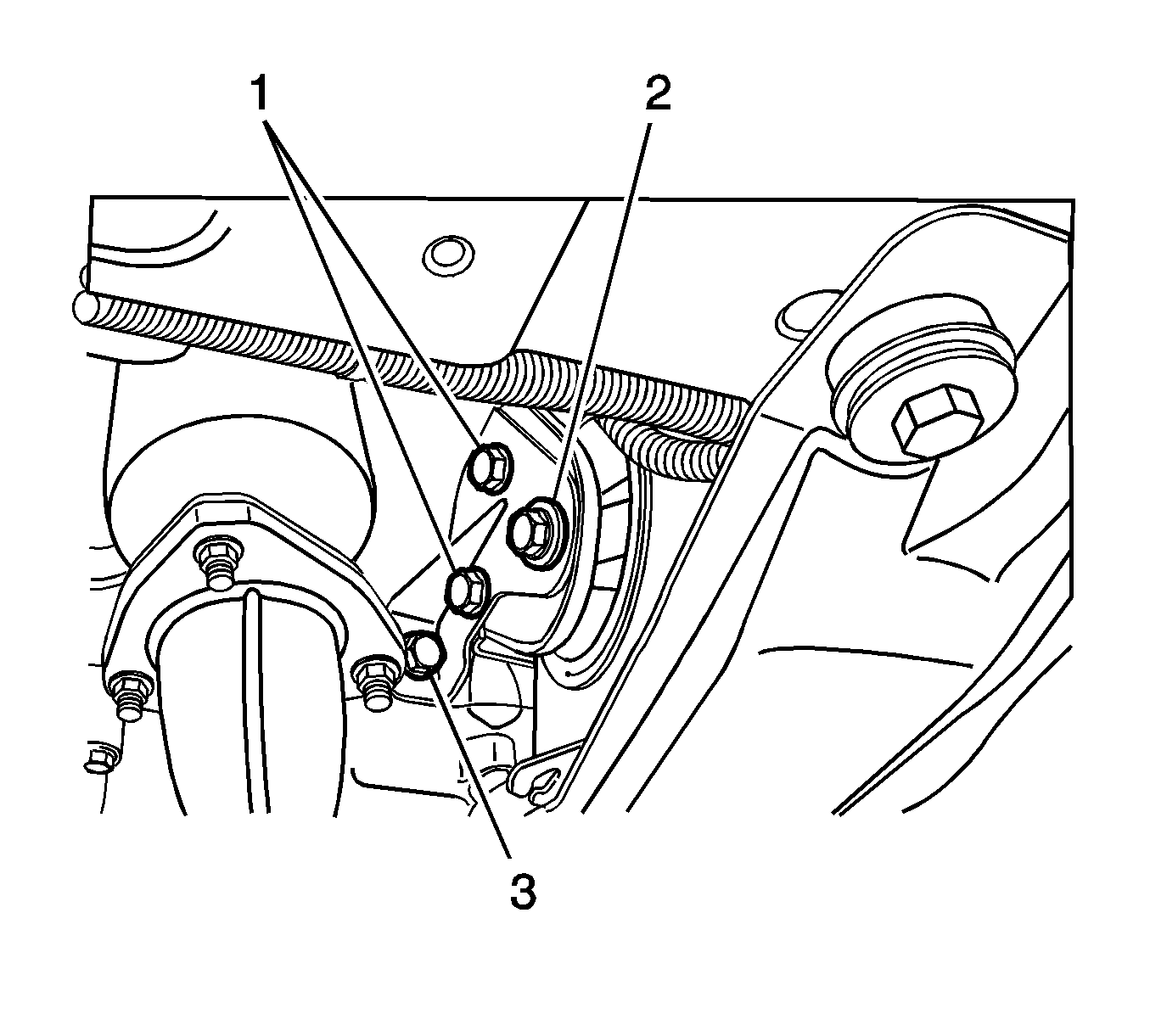
Tighten
| • | Tighten the front engine mounting bracket bolts (1) to 90 N·m (66 lb ft). |
| • | Tighten the front engine mounting bracket bolts (2) to 80 N·m (59 lb ft). |
| • | Tighten the front engine mounting bracket bolts (3) to 65 N·m (48 lb ft). |

Tighten
Tighten the converter to flywheel bolts to 45 N·m (33 lb ft).

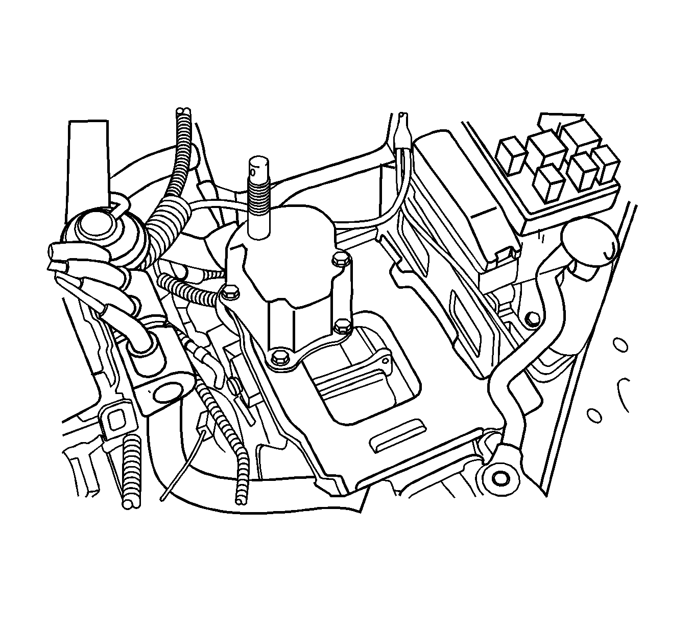
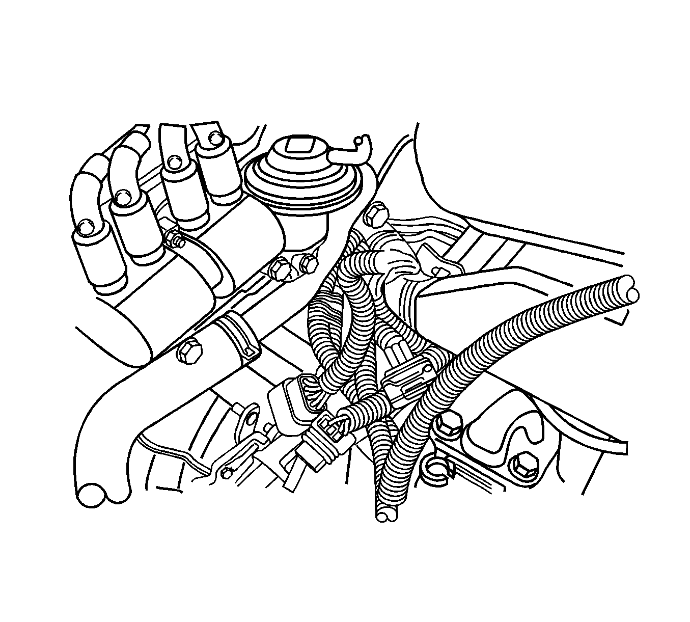
Tighten
Tighten the upper transaxle-to-engine bolts to 75 N·m (55 lb ft).


Important: After installing the transmission assembly, the shift adapts must be reset. reset the shift adapts using the scan tool. Go to "Trans Adaptives Reset" under "Special Functions" on the scan tool.
Transmission Replacement 2.5L DOHC
Tools Required
| • | J 28467-B (DW117) Universal Engine Support Fixture |
| • | DW 260-010 (DW260-010) Auto Transaxle Support Fixture |
Removal Procedure
- Disconnect the negative battery cable.
- Position the select lever in the PARK position.
- Remove the battery. Refer to Battery and Battery Tray Replacement in Engine Electrical.
- Remove the air filter housing.
- Install the J 28467-B (1) .
- Disconnect the transaxle wiring harness from the transaxle
- Disconnect the park/neutral position switch electrical connector.
- Remove the clips from the shift control cable. Disconnect the shift control cable from the transaxle.
- Remove the upper transaxle-to-engine bolts.
- Remove the left transaxle mounting bracket. Refer to Transmission Mount Bracket Replacement .
- Raise and suitably support the vehicle.
- Remove the front engine crossbar. Refer to Engine Front Crossmember Replacement in Front Suspension.
- Remove the impact bar. Refer to I-Beam Suspension Replacement in Front Suspension.
- Drain the transaxle fluid.
- Remove the oil cooler pipes from the transaxle. Refer to Transmission Fluid Cooler Hose/Pipe Replacement
- Remove the drive axle. Refer to Front Drive Axle Inner Shaft Replacement in front Drive Axle.
- Remove the starter motor. Refer to Starter Motor Replacement in Engine Electrical.
- Remove the flywheel to torque converter bolts.
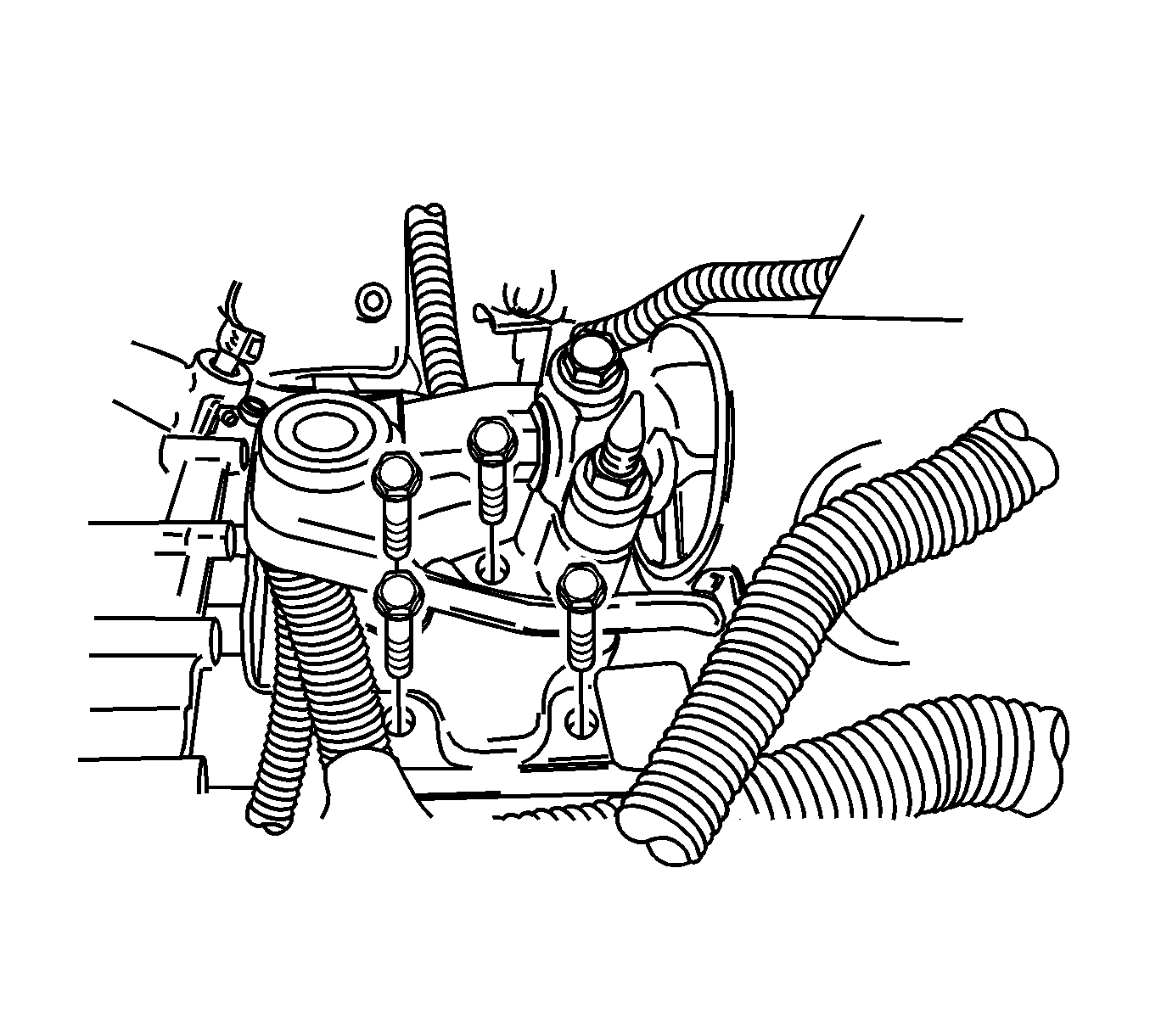
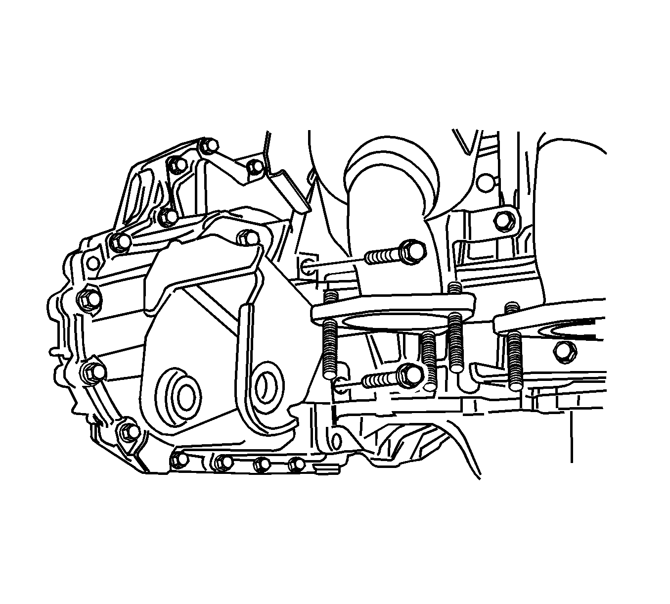
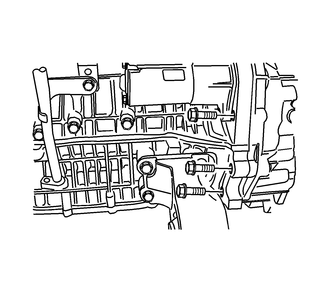
- Remove the rear transaxle mounting bracket bolts.
- Support the transaxle assembly using DW 260-010 (1).
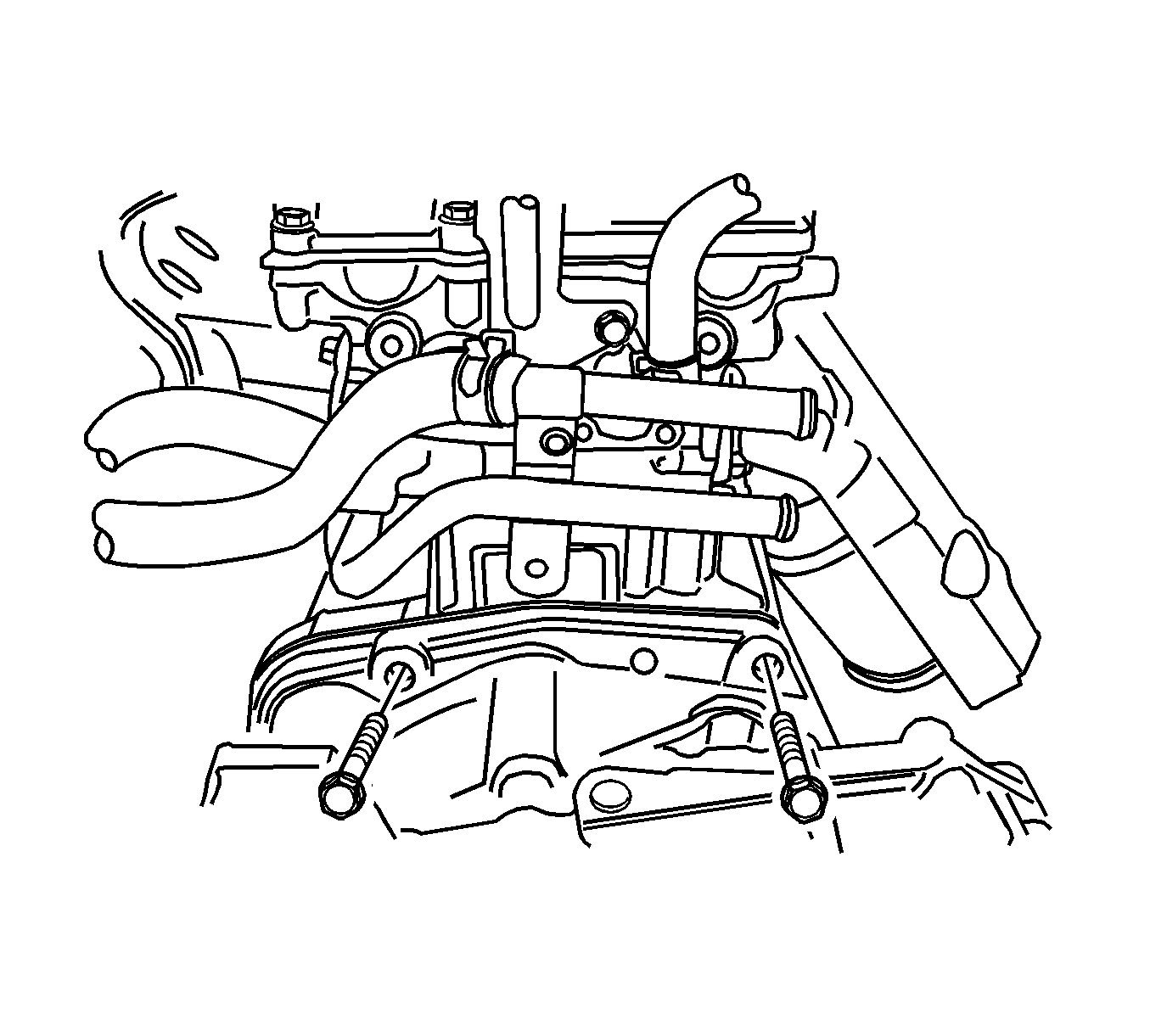
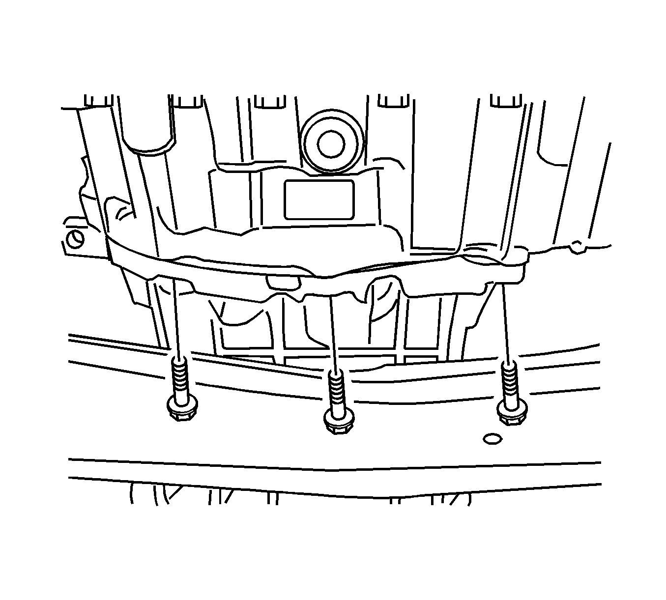
- Remove the oil pan flange-to-transaxle bolts.
- Remove the left lower engine to transaxle mounting bolts from the rear transaxle mounting bracket side.
- Remove the right lower engine to transaxle mounting bolts.
- Remove the transaxle assembly.
Caution: Refer to Battery Disconnect Caution in the Preface section.

Notice: Refer to Vehicle Lifting and Jacking Notice in the Preface section.


Installation Procedure
- Install the transaxle into the vehicle.
- Use the DW 260-010 (1) or equivalent to support the transaxle assembly .
- Install the right lower engine-to-transaxle mounting bolts.
- Install the left lower engine to transaxle mounting bolts.
- Install the oil pan flange to transaxle bolts.
- Install the rear transaxle mounting bracket bolts.
- Install the flywheel to torque converter bolts.
- Install the starter motor. Refer to Starter Motor Replacement in Engine Electrical.
- Install the drive axle. Refer to Front Drive Axle Inner Shaft Replacement in Front Drive Axle.
- Install the oil cooler pipes from the transaxle. Refer to Transmission Fluid Cooler Hose/Pipe Replacement .
- Install the impact bar. Refer to I-Beam Suspension Replacement in Front Suspension.
- Install the front engine cross-member. Refer to Engine Front Crossmember Replacement in Front Suspension.
- Lower the vehicle.
- Install the transmission mounting bracket. Refer to Transmission Mount Bracket Replacement .
- Install the upper transaxle to engine mounting bolts.
- Install the clips to the shift control cable and connect the shift cable.
- Install the park/neutral position switch electrical connector.
- Connect the transaxle wiring harness to the transaxle.
- Remove the J 28467-B (1) .
- Install the air filter housing.
- Install the battery. Refer to Battery and Battery Tray Replacement in Engine Electrical.
- Add the transaxle fluid. Refer to Transmission Fluid Level Inspection .
- Connect the negative battery cable.
Important: After installing the transmission assembly, the shift adapts must be reset. reset the shift adapts using the scan tool. Go to "Trans Adaptives Reset" under "Special Functions" on the scan tool.

Notice: Refer to Fastener Notice in the Preface section.

Tighten
Tighten the right lower engine-to-transaxle mounting bolts to 73 N·m (54 lb ft).

Tighten
Tighten the rear transaxle mounting bracket bolts to 73 N·m (54 lb ft).

Tighten
Tighten the oil pan flange to transaxle bolts to 31 N·m (23 lb ft).

Tighten
Tighten the rear transaxle mounting bracket bolts to 65 N·m (48 lb ft)


Tighten
Tighten the upper transaxle to engine mounting bolts to 73 N·m (54 lb ft).


Important: After installing the transmission assembly, the shift adapts must be reset. reset the shift adapts using the scan tool. Go to "Trans Adaptives Reset" under "Special Functions" on the scan tool.
