Tools Required
KM-507-C Ball Joint Remover
Removal Procedure
- Disconnect the negative battery cable. Refer to Battery Negative Cable Disconnection and Connection .
- Raise and support the vehicle. Refer to Lifting and Jacking the Vehicle .
- Lock the steering column in the straight-ahead position.
- Remove the front tire and wheel assemblies. Refer to Tire and Wheel Removal and Installation .
- Place a drain pan under the steering gear in order to catch the power steering fluid.
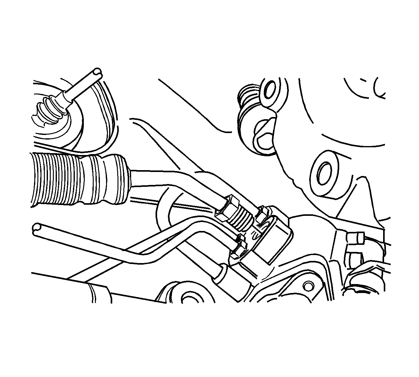
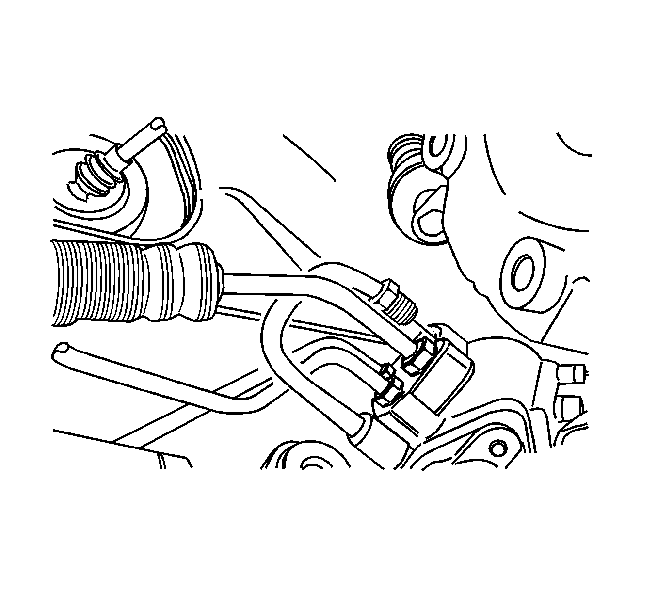
- Loosen the fitting and remove the pressure pipe from the power steering gear fluid inlet.
- Loosen the fitting and remove the return pipe from the power steering gear fluid outlet.
- Ensure the steering gear is in the straight-ahead position.
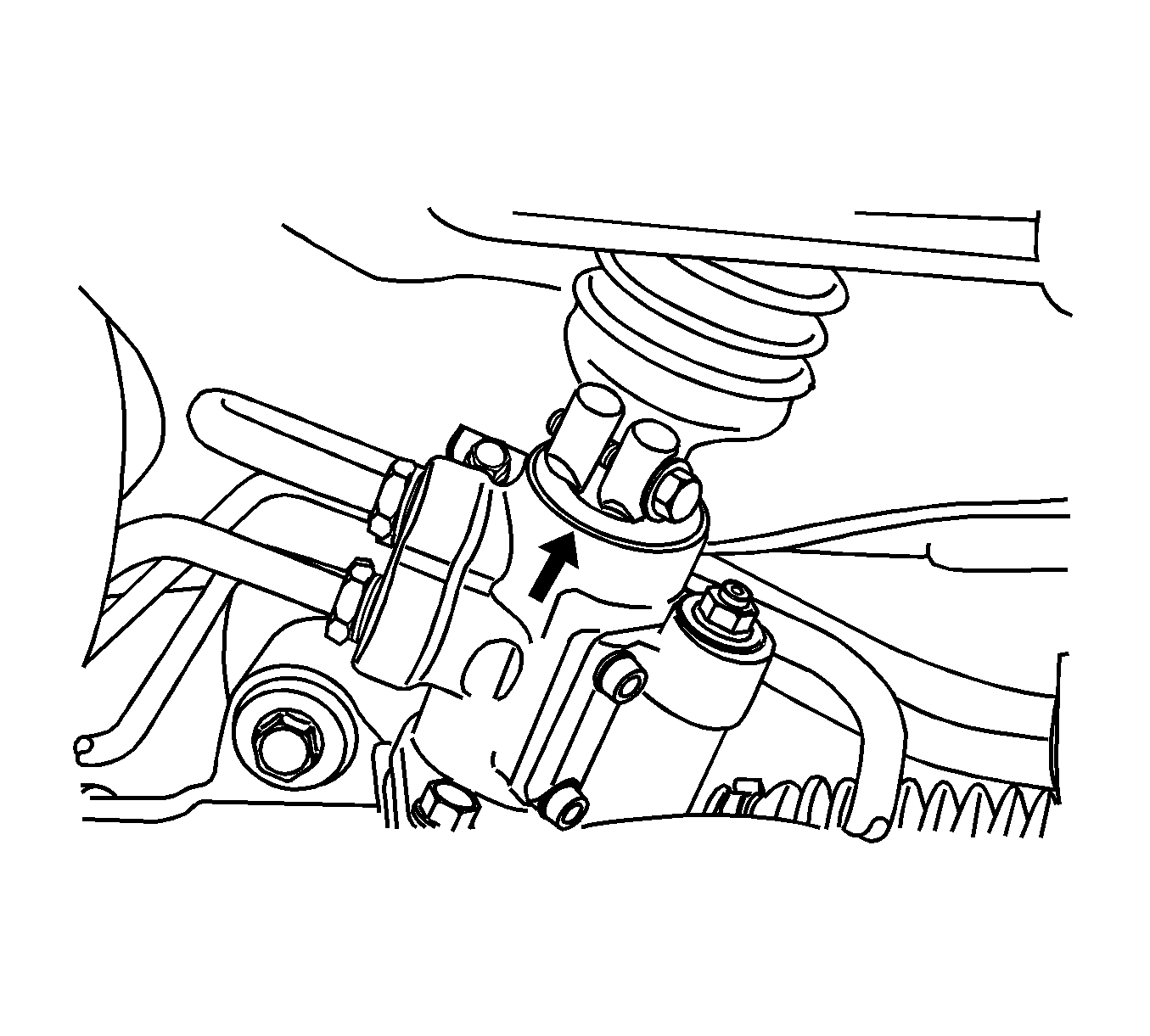
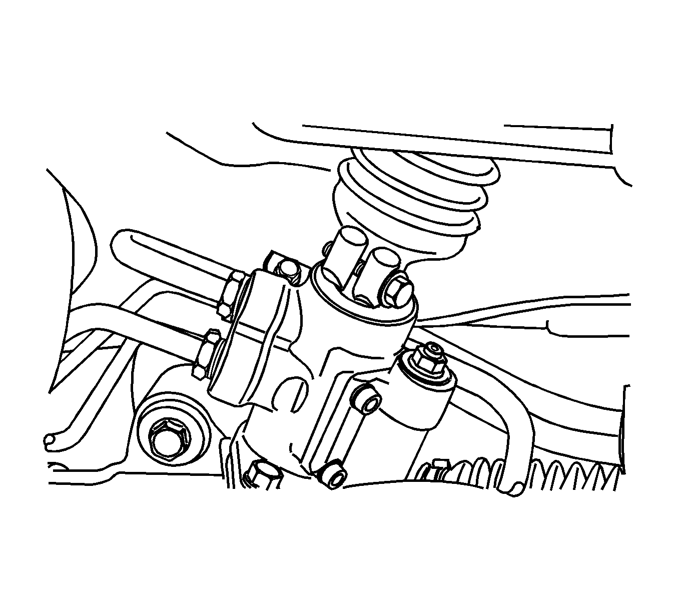
- Scribe a mark on the stub shaft housing that lines up with a mark on the intermediate shaft lower coupling.
- Remove the intermediate shaft pinch bolt.
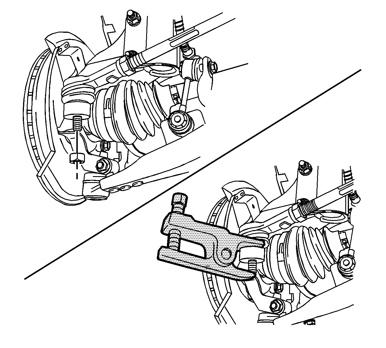
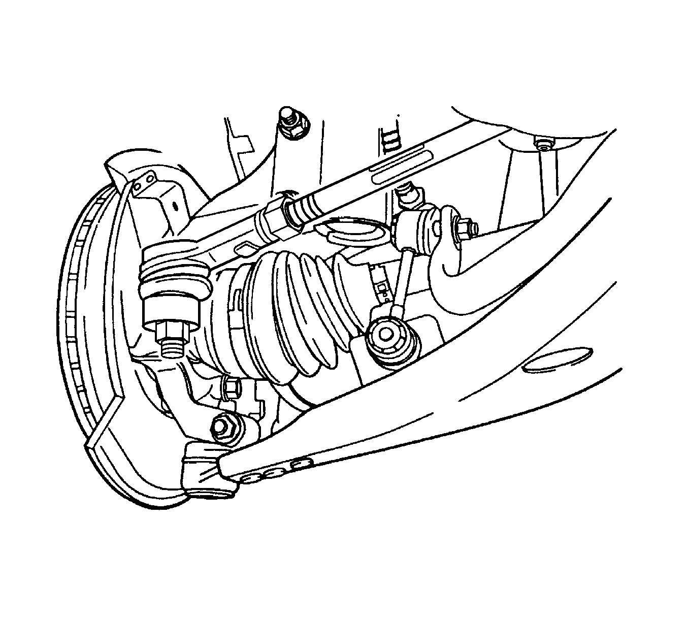
- Remove the outer tie rod nuts and disconnect the tie rod ends from the knuckle using the KM-507-C .
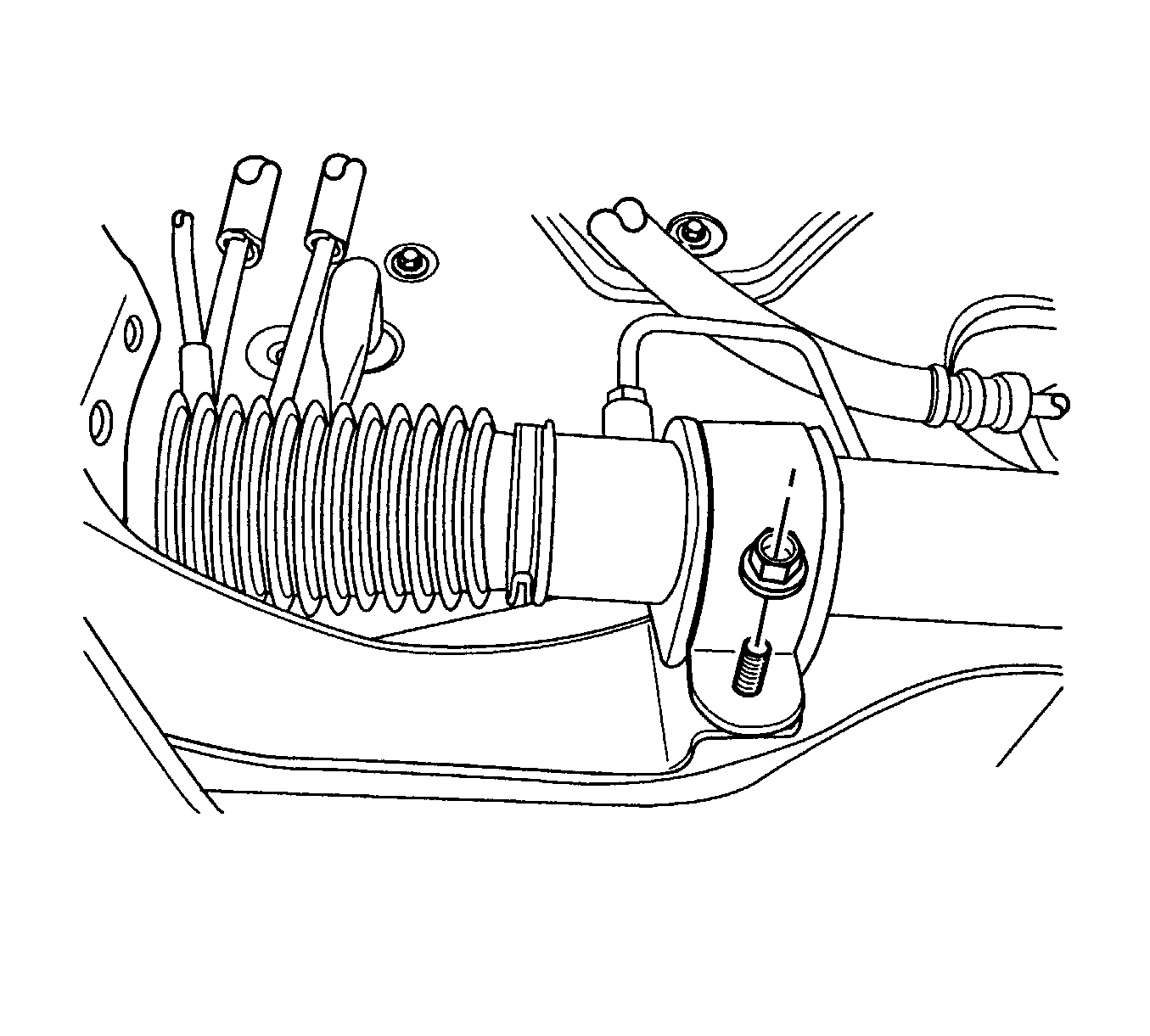
- Lower the crossmember assembly enough in order to access of the rack and pinion assembly. Refer to Front Suspension Crossmember Replacement .
- Remove the nuts and bolts from the steering gear mounting brackets.
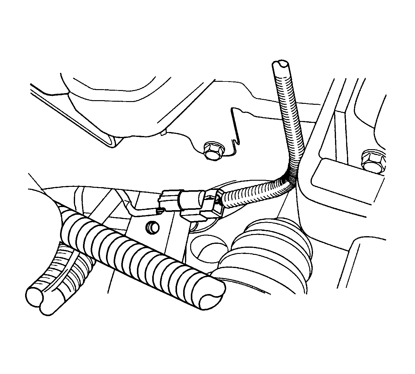
- Disconnect the speed sensitive power steering (SSPS) solenoid valve connector.
- Remove the rack and pinion assembly from the crossmember assembly.
Notice: Refer to Steering Column in Lock Position Notice in the Preface section.
Notice: Refer to Power Steering Hose Disconnected Notice in the Preface section.
Caution: Failure to support crossmember can cause crossmember to drop to the ground when crossmember mounting bolts are removed.
Installation Procedure
- Verify the steering gear and the steering wheel are in the straight-ahead position.
- Install the rack and pinion assembly from below. Align the marks on the shafts in order to ensure proper positioning. Seat the stub shaft into the intermediate shaft.
- Connect the SSPS solenoid valve connector.
- Install the nuts and bolts on the steering gear mounting bracket.
- Install the crossmember. Refer to Front Suspension Crossmember Replacement .
- Connect the tie rod ends to the knuckle.
- Install the outer tie rod nuts.
- Install the lower intermediate shaft pinch bolt.
- Connect the pressure pipe to the power steering gear fluid inlet.
- Connect the return pipe to the power steering gear fluid outlet.
- Install the front tire and wheel assemblies. Refer to Tire and Wheel Removal and Installation .
- Lower the vehicle.
- Refill the power steering system and check for leaks. If the leaks are found, correct the cause of the leak and bleed the system. Refer to Power Steering System Bleeding .
- Connect the negative battery cable. Refer to Battery Negative Cable Disconnection and Connection .
- Inspect the vehicle. Refer to Preliminary Alignment Inspection and to Straight Ahead Inspection .
- Measure the wheel alignment.
- If necessary, adjust the front toe. Refer to Front Toe Adjustment .


Notice: Refer to Fastener Notice in the Preface section.

Tighten
Tighten the steering gear mounting bracket bolts and nuts to 60 N·m (44 lb ft).
Tighten
Tighten the outer tie rod nuts to 50 N·m (37 lb ft).
Tighten
Tighten the intermediate shaft pinch bolt to 25 N·m (18 lb ft).
Notice: Refer to Installing Hoses without Twists or Bends Notice in the Preface section.

Tighten
Tighten the pressure pipe fitting to 28 N·m (21 lb ft).

Tighten
Tighten the return pipe fitting to 28 N·m (21 lb ft).
Notice: Refer to Using Proper Power Steering Fluid Notice in the Preface section.
Notice: Refer to Air in the Power Steering System Notice in the Preface section.
