For 1990-2009 cars only
Disassembly Procedure
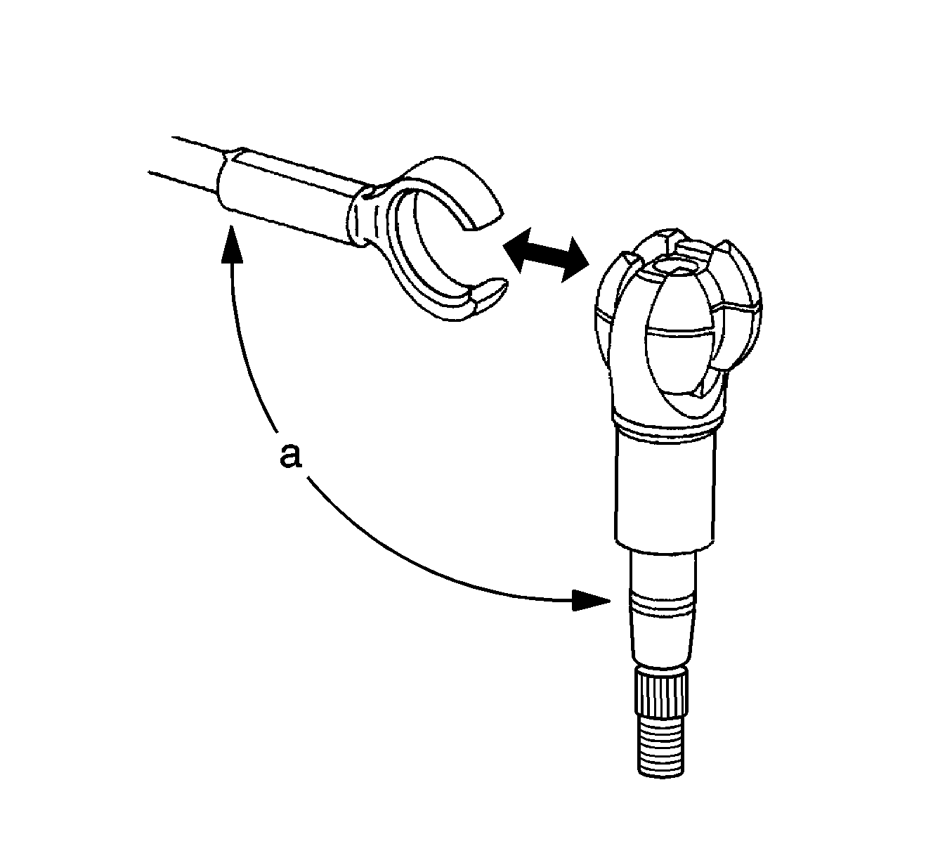
- Position the upper shaft 90 degrees (a) to the lower shaft and separate the 2 parts.
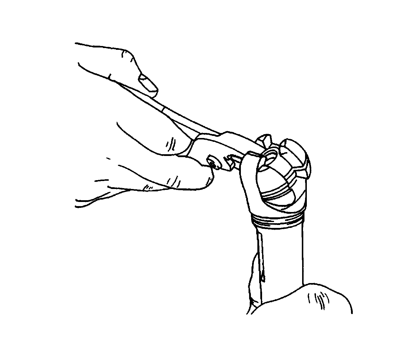
- Rotate the centering sphere 90 degrees and remove it from the upper shaft.
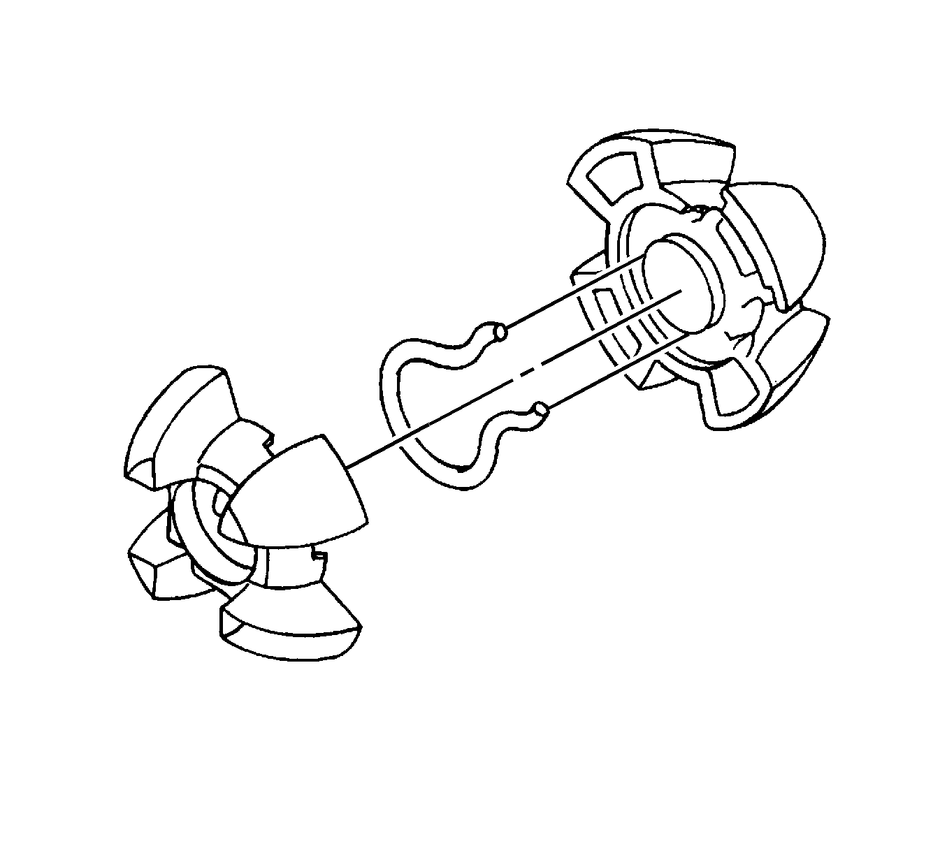
- Separate the sphere halves and remove the joint preload spring.

Important: Prior to separating the upper shaft from the lower shaft, note the relationship of the upper shaft, with the lock bolt slot at the 12 o'clock position, to the lower shaft pinch bolt groove at the 7 o'clock position.


Assembly Procedure
- Lubricate the centering sphere halves and the joint preload spring with lithium grease.
- Place the joint preload spring between the sphere halves with the ends of the spring in the notches.
- Lubricate the sphere end of the upper shaft with lithium grease.
- Place the sphere into the upper shaft and rotate the sphere 90 degrees.
- Lubricate the sphere end of the lower shaft with lithium grease.
- Place the lock bolt slot on the upper shaft at the 12 o'clock position.
- Place the pinch bolt groove near the end of the lower shaft at the 7 o'clock position.
- Connect the upper shaft to the lower shaft.


Important: To insure proper operation, the upper shaft and the lower shaft must be aligned correctly when they are connected.
