For 1990-2009 cars only
Tools Required
J 28467-B (DW-110-060) Universal Engine Support Fixture
Removal Procedure
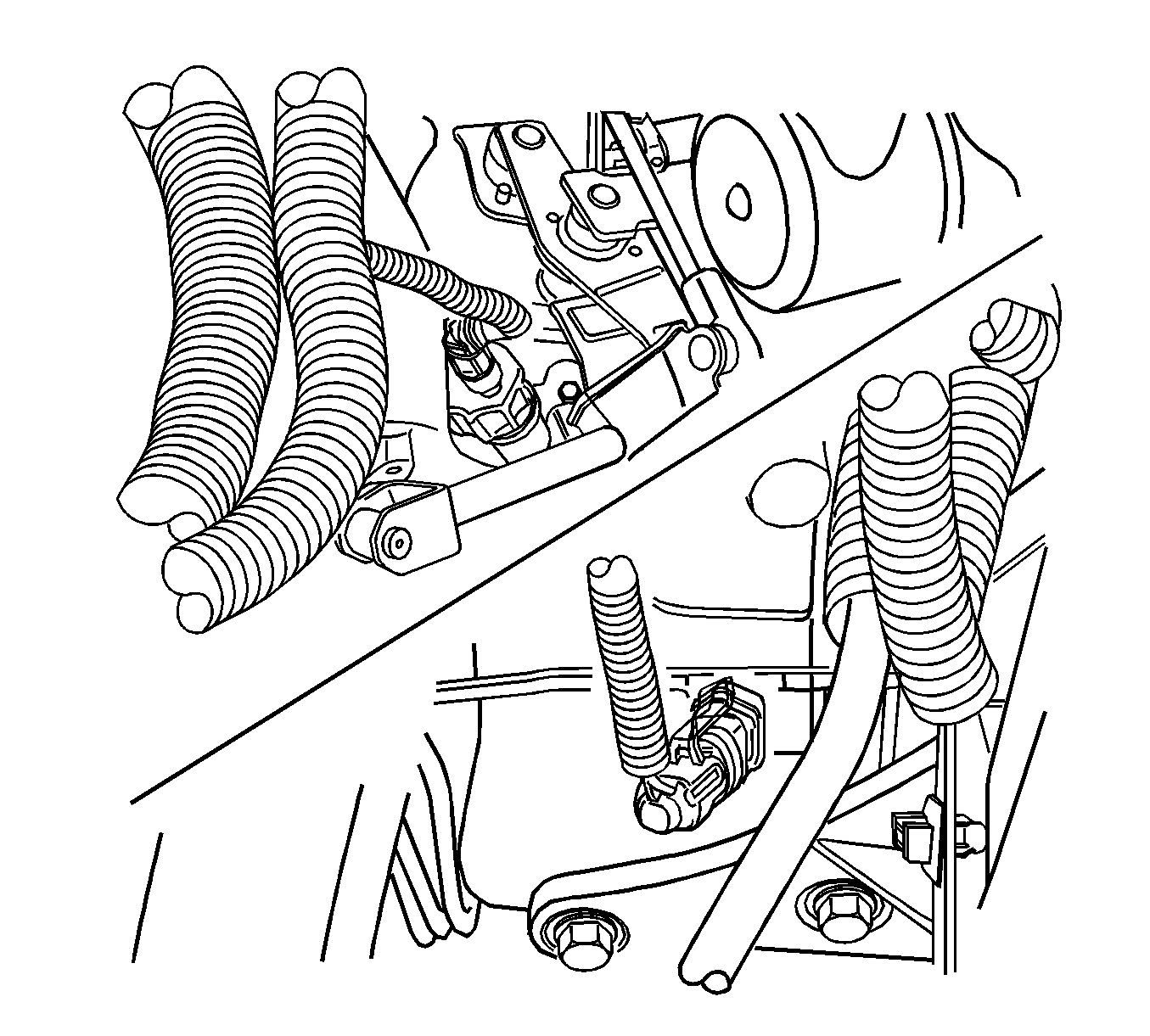
- Disconnect the backup lamp switch electrical connector.
- Disconnect the speedometer speed sensor electrical connector.
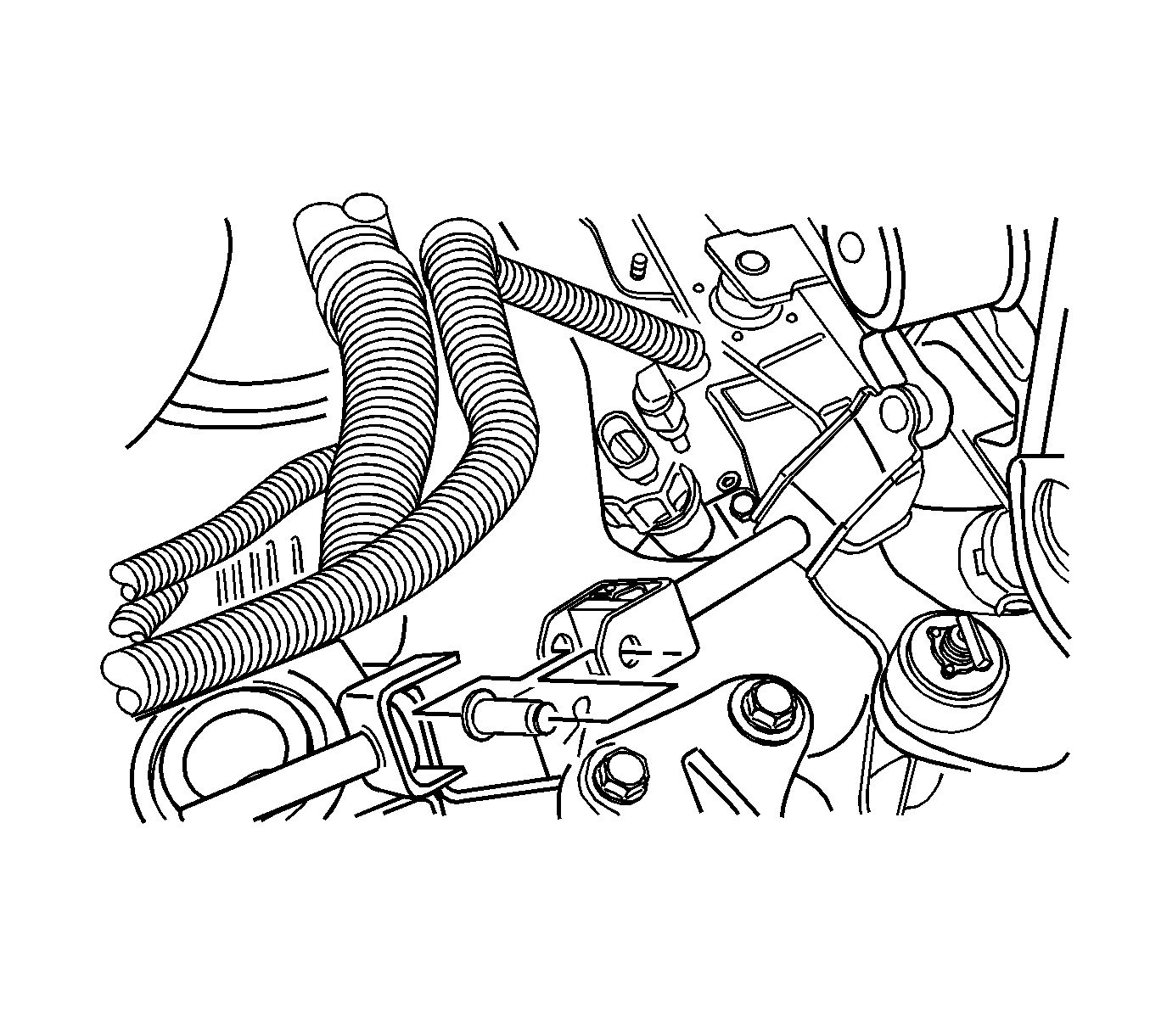
- Remove the clip and the bolt from the universal joint.
- Remove the clutch release cylinder bracket bolts and the clutch release cylinder bracket.
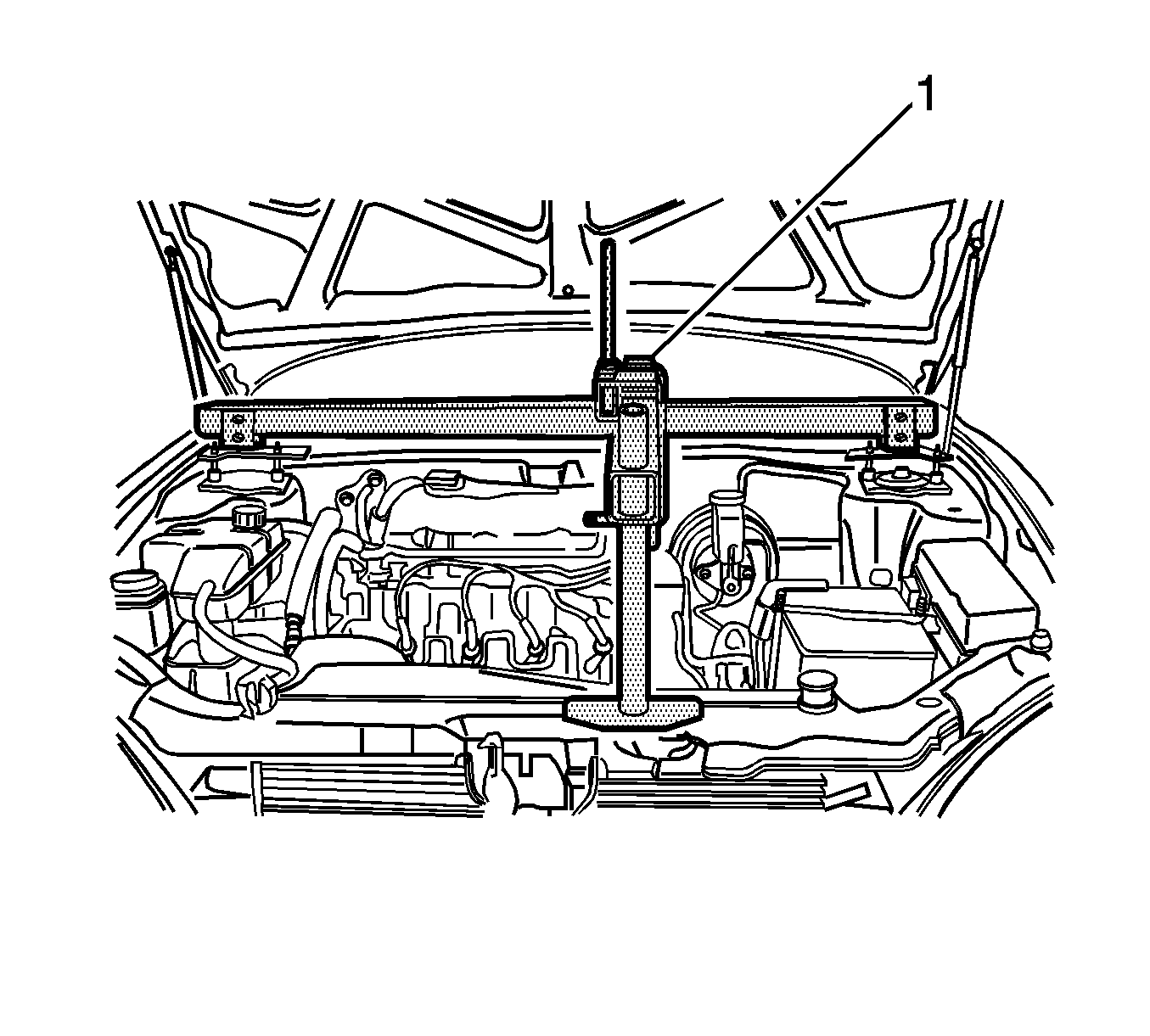
- Install the J 28467-B (1).
- Remove the transaxle-to-engine upper bolts.
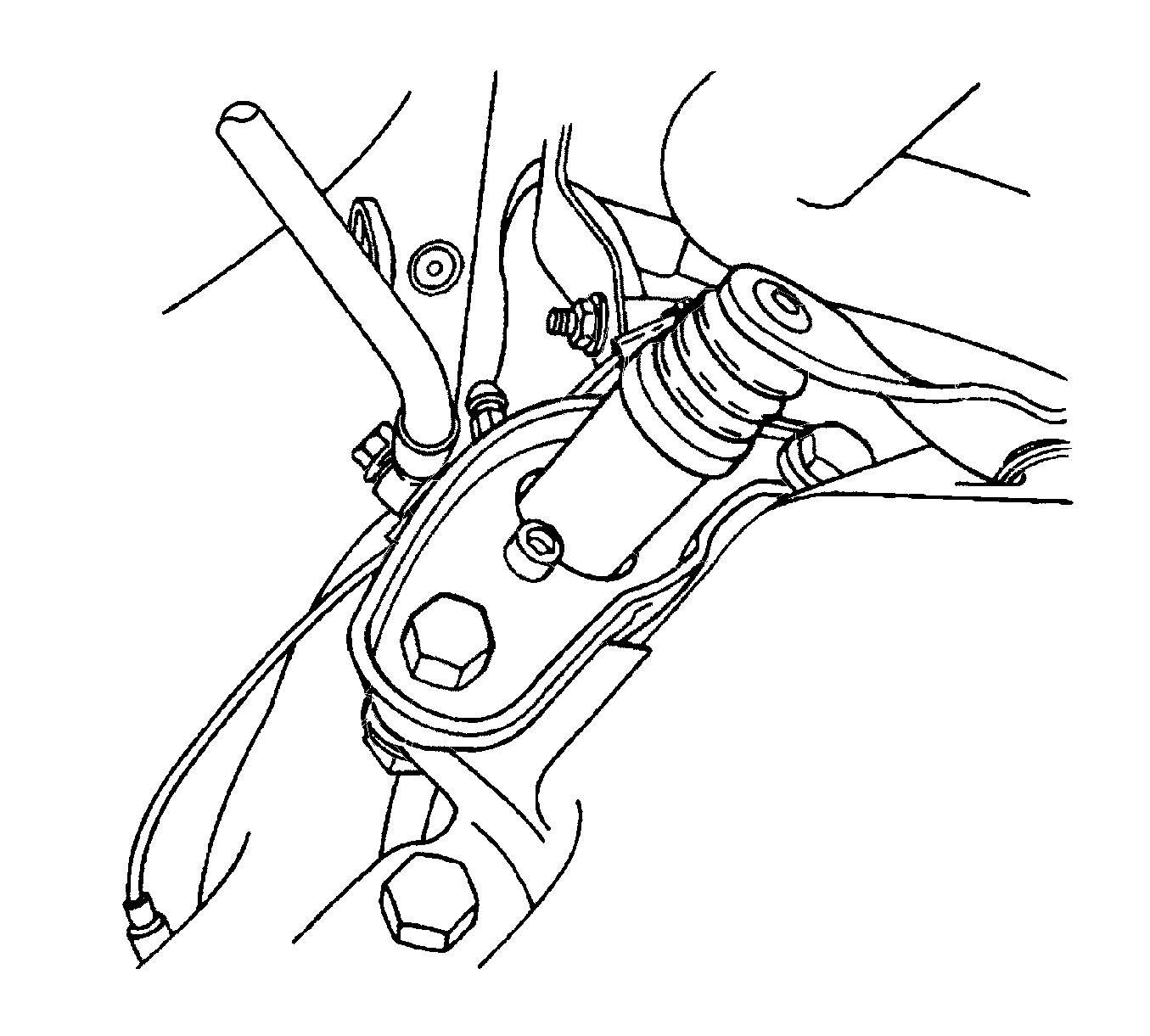
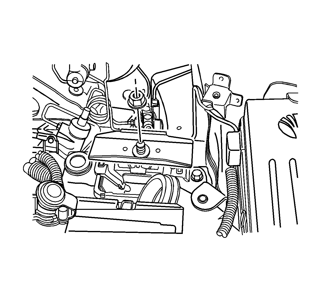
- Remove the left front transaxle mounting bracket nut.
- Raise and suitably support the vehicle. Refer to Lifting and Jacking the Vehicle .
- Remove both of the drive axle shafts. Refer to Front Drive Axle Inner Shaft Replacement .
- Support the transaxle with a transaxle support jack.
- Remove the crossmember. Refer to Front Suspension Crossmember Replacement .
- Remove the exhaust pipe nuts. Refer to Front Pipe Replacement .
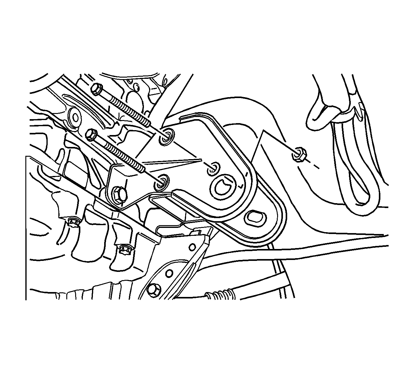
- Remove the front transaxle mounting bracket bolts and nut.
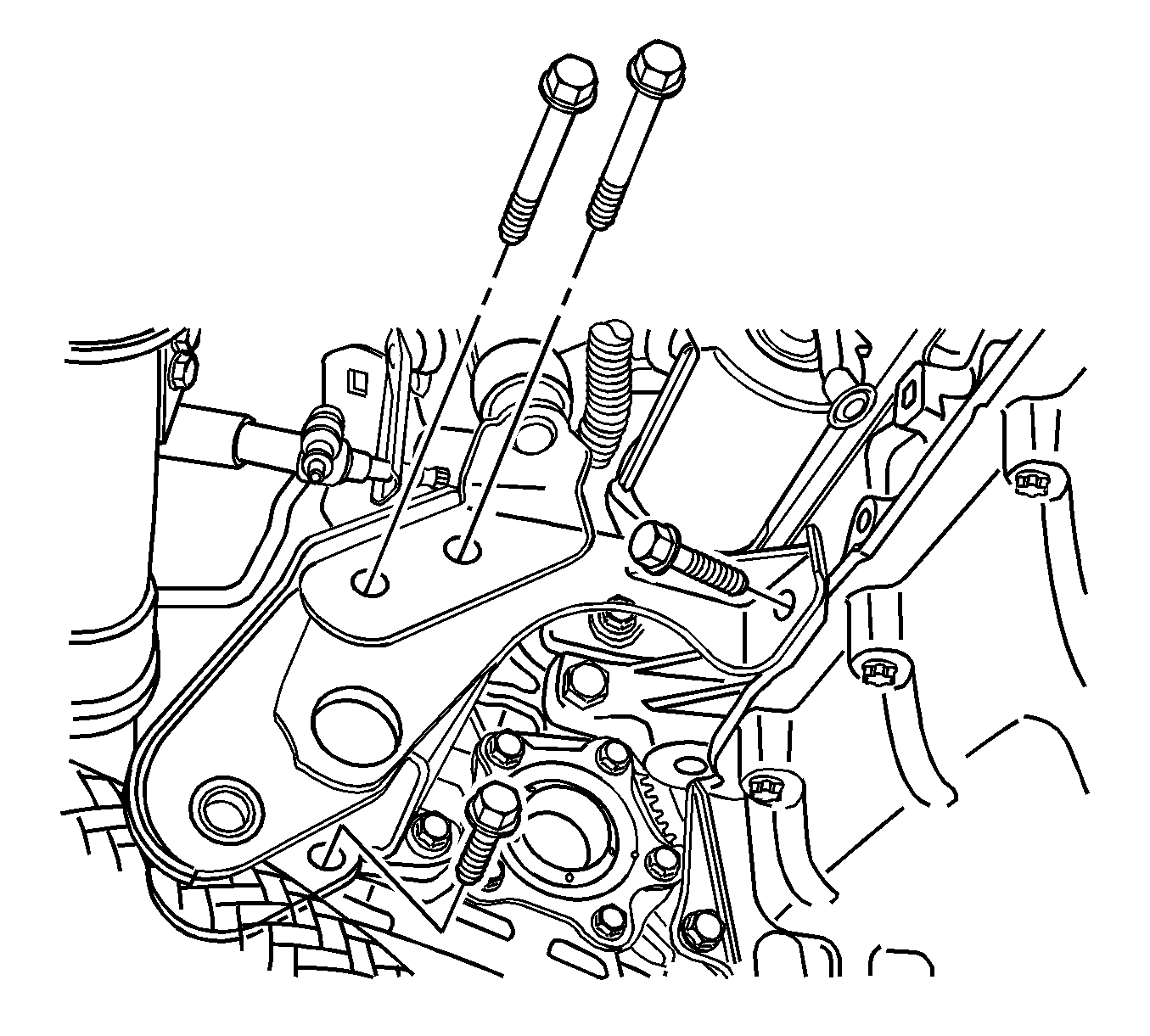
- Remove the rear transaxle mounting bracket bolts and bracket.
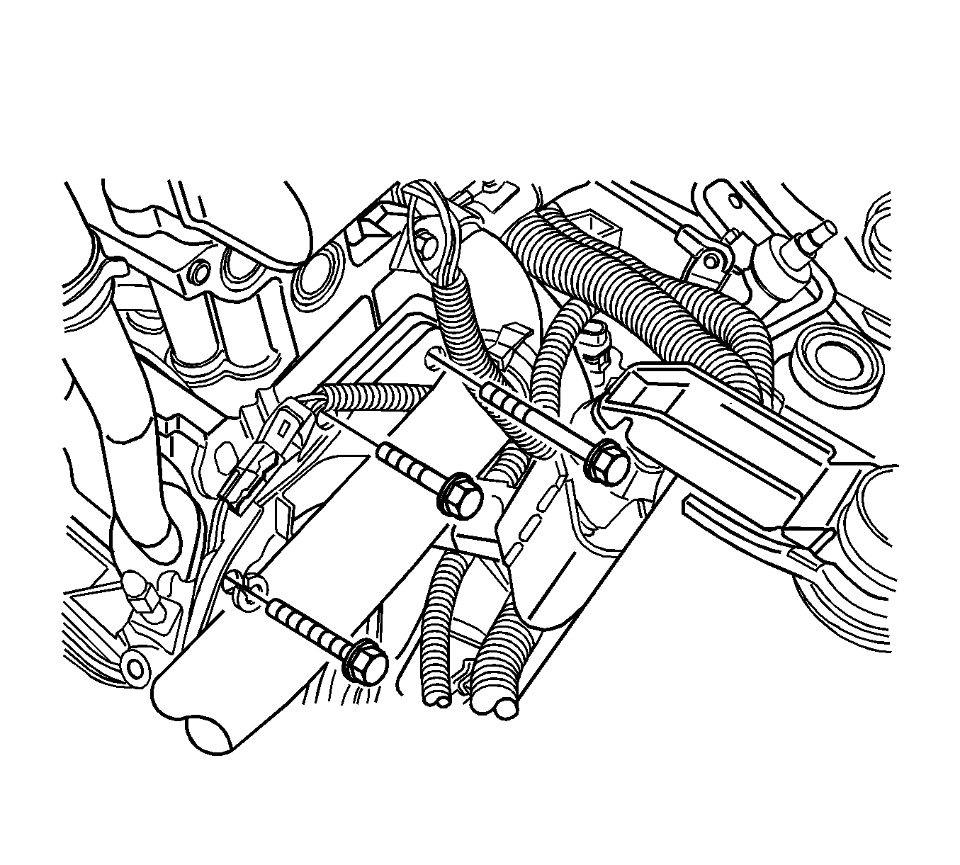
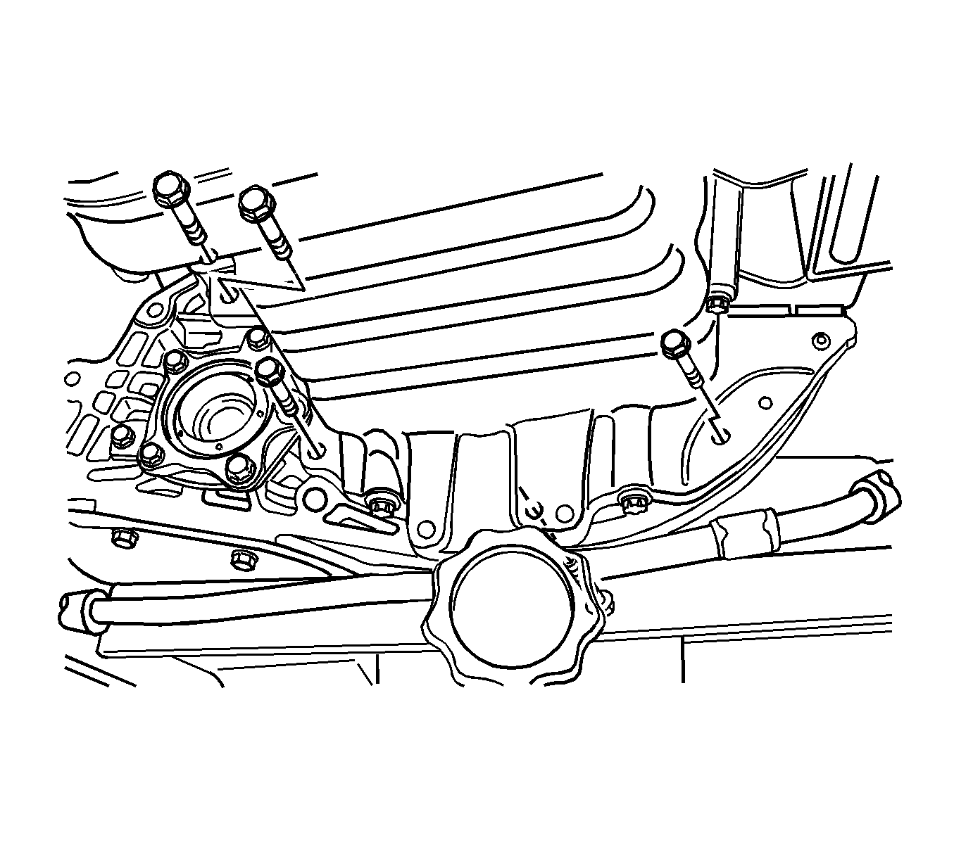
- Remove the transaxle-to-engine lower bolts.
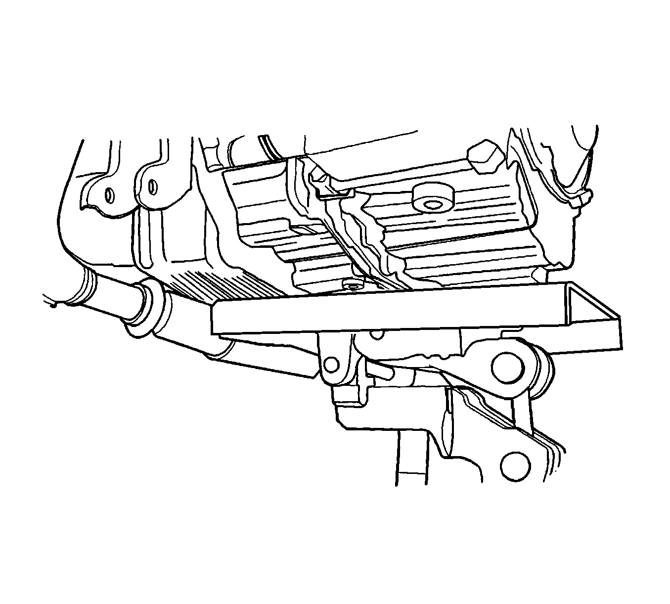
- Slide the transaxle sideways away from the engine block.
- Lower the transaxle.
Notice: When removing or installing the backup lamp switch, do not use an open end wrench. Use only a socket in order to avoid damage to the switch assembly.
Installation Procedure
- Support the transaxle with a transaxle support jack.
- Install the transaxle by inserting the transaxle input shaft into the clutch disc and sliding the transaxle sideways into the engine block.
- Install the transaxle-to-engine lower bolts.
- Install the rear transaxle mounting bracket and the bolts.
- Install the front transaxle mounting bracket bolts and the nut.
- Install the exhaust pipe nuts. Refer to Front Pipe Replacement .
- Install the crossmember. Refer to Front Suspension Crossmember Replacement .
- Install the drive axles. Refer to Front Drive Axle Inner Shaft Replacement .
- Install the left front transaxle mounting bracket nut.
- Install the upper transaxle-to-engine bolts.
- Remove the J 28467-B (1).
- Install the clutch release cylinder bracket and the clutch release cylinder bracket bolts.
- Install the bolt and the clip onto the universal joint.
- Connect the speedometer speed sensor electrical connector.
- Connect the backup lamp switch electrical connector.
- Inspect the fluid level. Refer to Transmission Fluid Level Inspection .

Notice: Refer to Fastener Notice in the Preface section.
Tighten
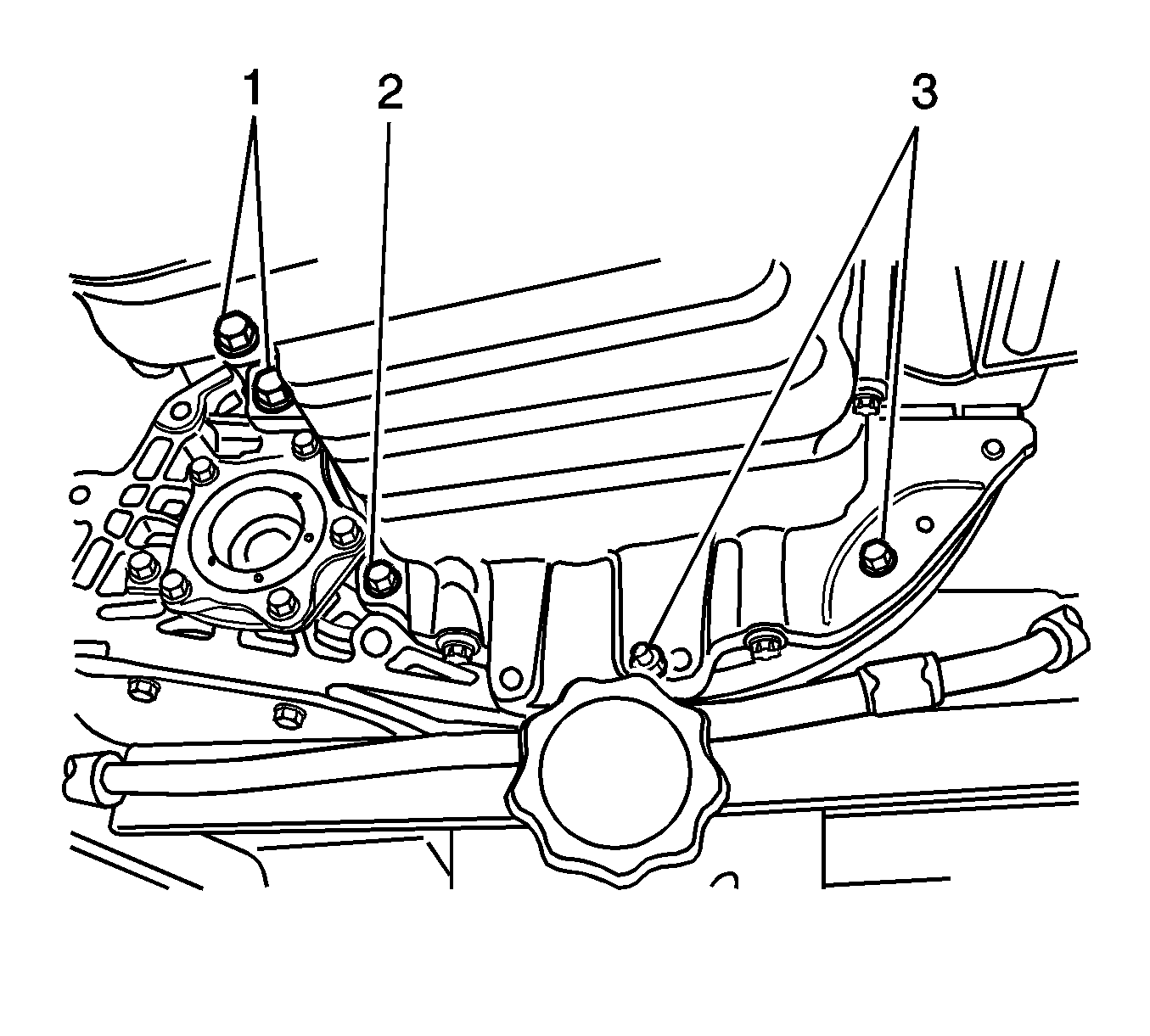
| • | Tighten the transaxle-to-engine lower bolts (1) to 75 N·m (55 lb ft). |
| • | Tighten the transaxle-to-engine lower bolt (2) to 21 N·m (15 lb ft). |
| • | Tighten the transaxle-to-engine lower bolts (3) to 31 N·m (23 lb ft). |
Tighten
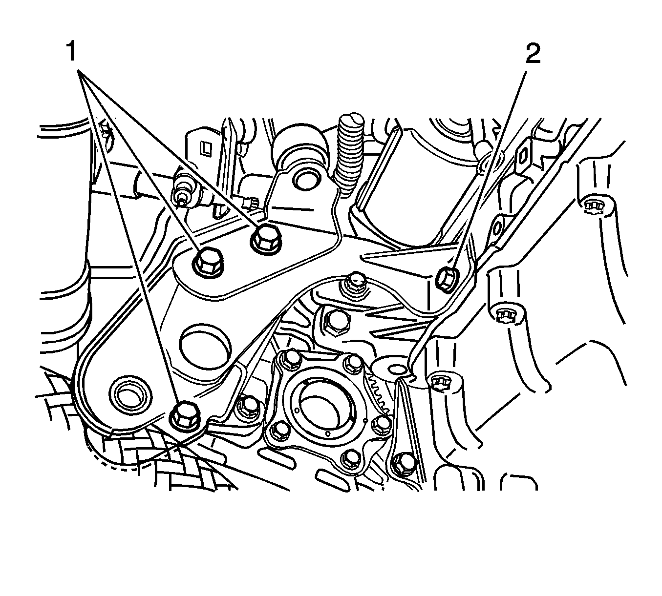
| • | Tighten the rear transaxle mounting bracket bolts (1) to 90 N·m (66 lb ft). |
| • | Tighten the rear transaxle mounting bracket bolt (2) to 65 N·m (48 lb ft). |
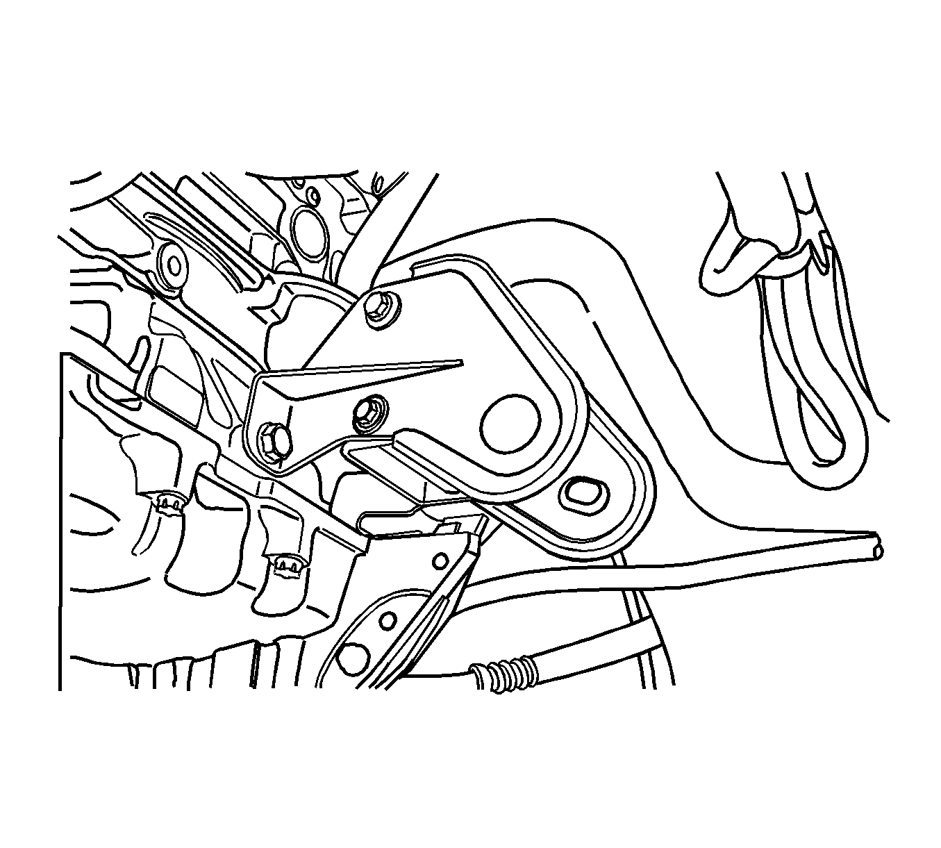
Tighten
Tighten the front transaxle mounting bracket bolts and nut to 90 N·m (66 lb ft).
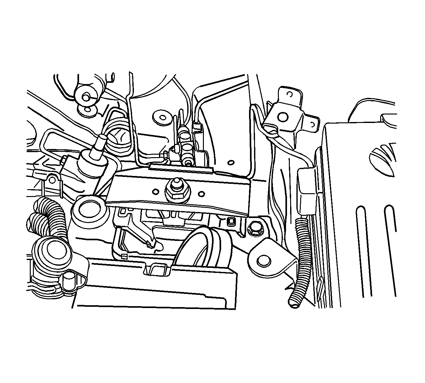
Tighten
Tighten the nut to 155 N·m (114 lb ft).
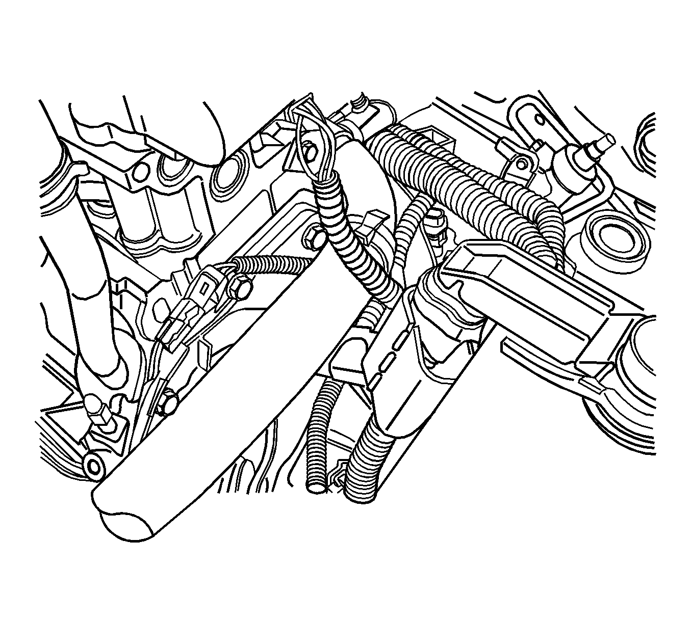
Tighten
Tighten the transaxle-to-engine upper bolts to 75 N·m (55 lb ft).


Tighten
Tighten the clutch release cylinder bracket bolts to 75 N·m (55 lb ft).


