For 1990-2009 cars only
Removal Procedure
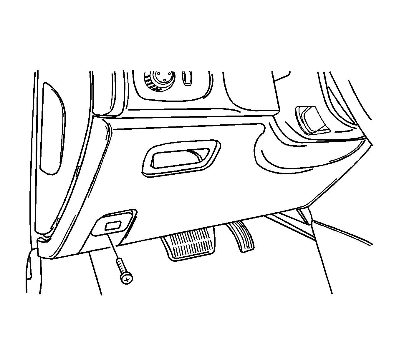
- Remove the screws that hold the trim panel to the instrument panel.
- Remove the trim panel.
- Remove the driver side knee bolster. Refer to Knee Bolster Replacement .
- Remove the stop lamp switch. Refer to Stop Lamp Switch Replacement .
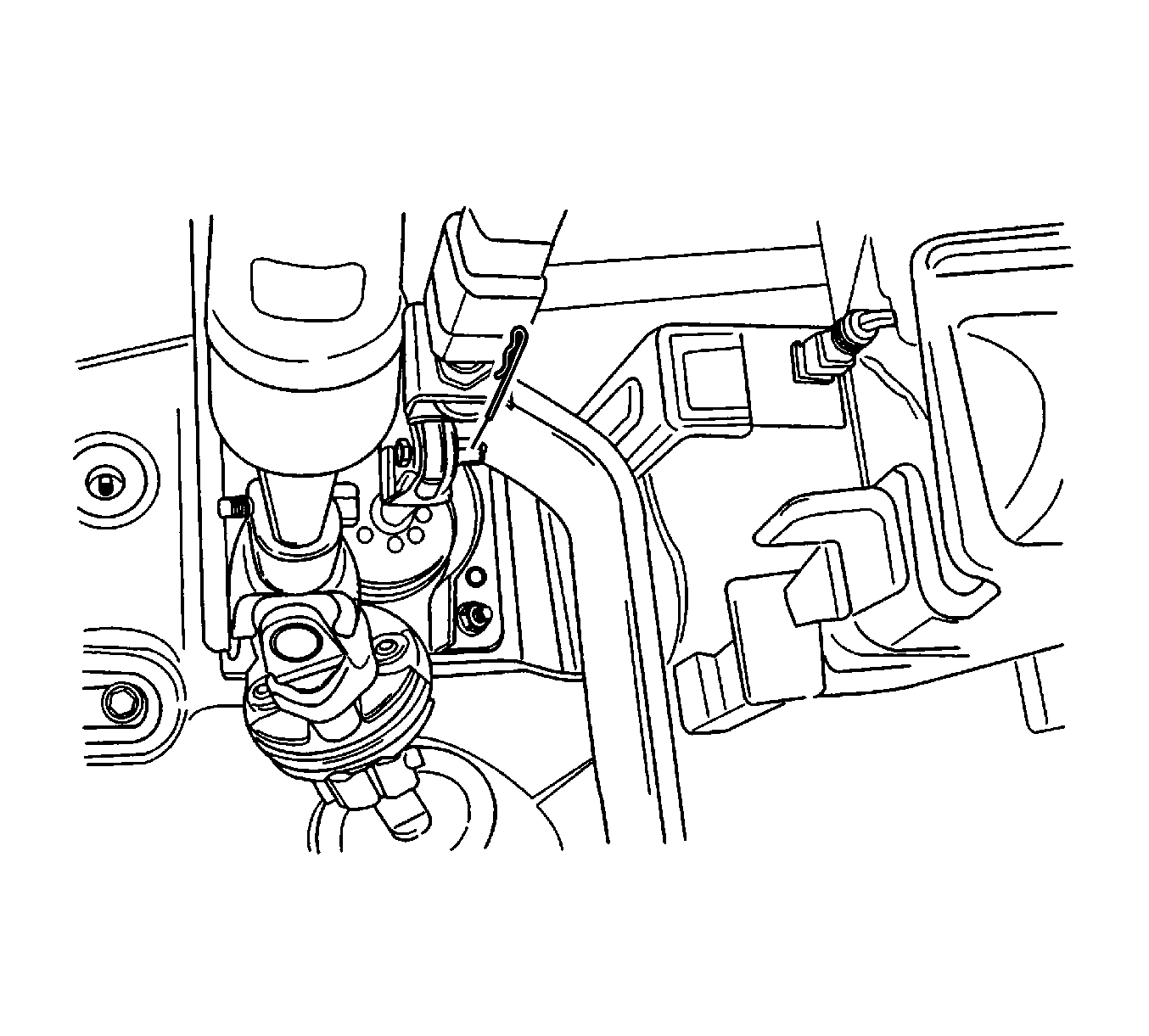
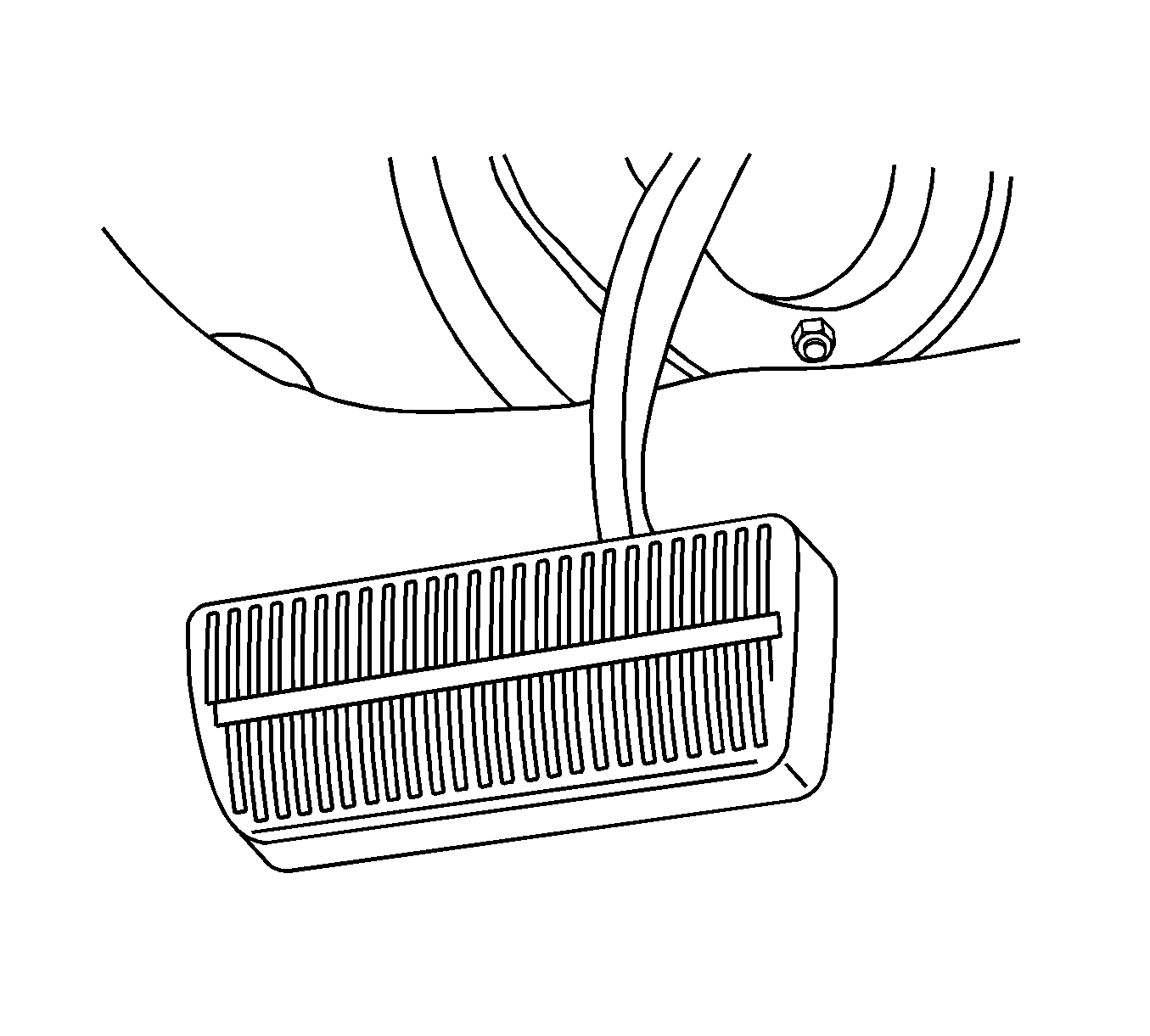
- Disconnect the spring retaining clip and the bolt from the pushrod clevis.
- Remove the hex nut and the spring.
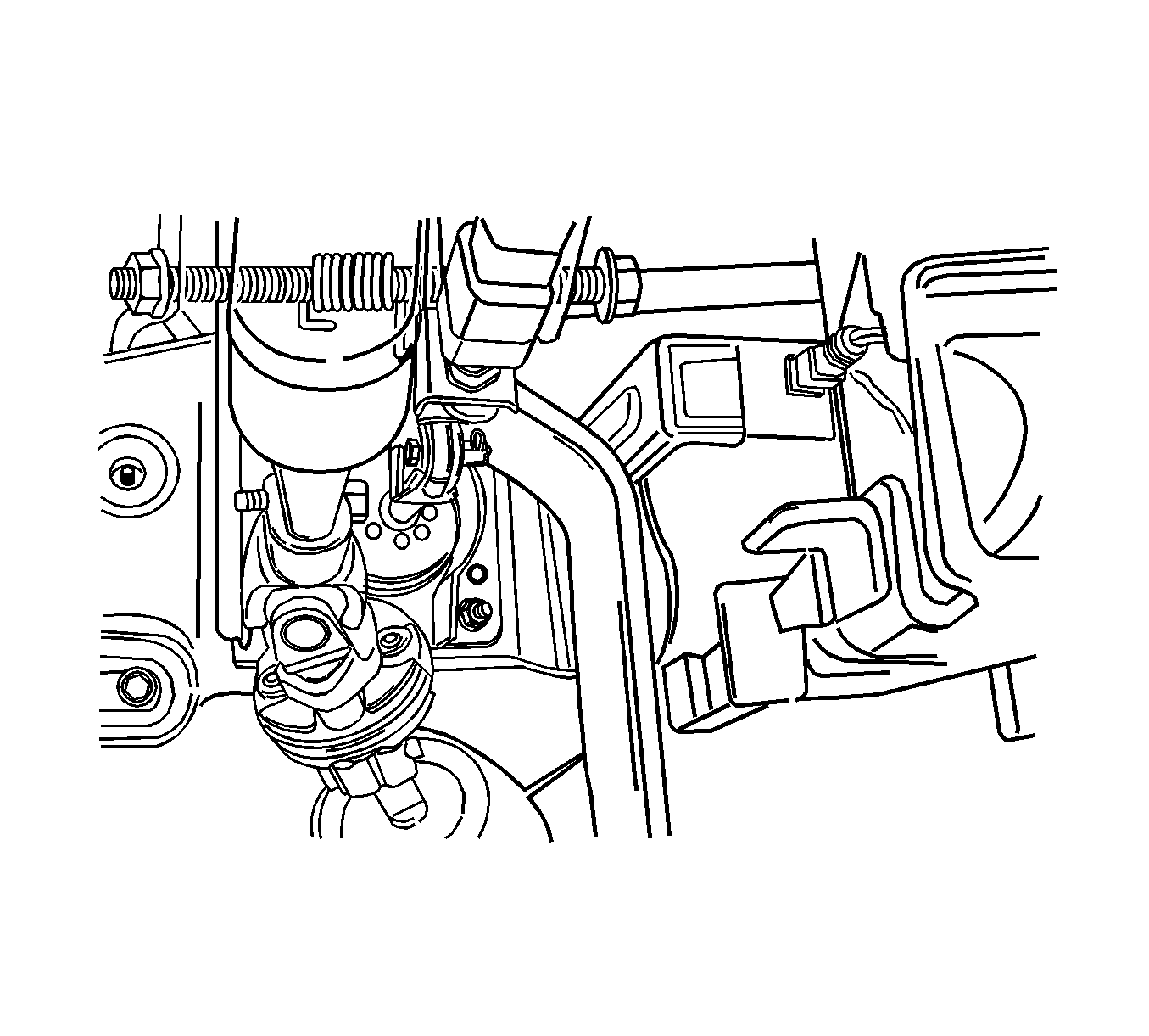
- Remove the brake pedal and the bolt.
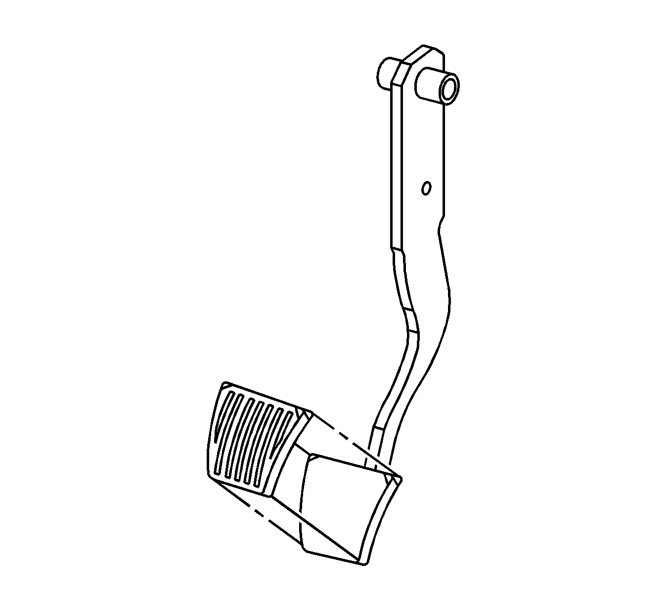
- Remove the brake pedal cover. Manual transaxle pedal shown
Installation Procedure
- Install a new pedal cover, if needed. Automatic transaxle pedal shown
- Coat the pedal shaft with grease.
- Position the brake pedal on the pedal-to-dash panel bracket and the pedal bolt.
- Place the hex nut and the spring on the pedal bolt.
- Install the pushrod clevis to the pedal with the bolt and the spring retaining clip.
- Connect the stop lamp switch and connector assembly to the pedal bracket. Refer to Stop Lamp Switch Replacement .
- Install the knee bolster. Refer to Knee Bolster Replacement .
- Install the trim panel with the screws.
Notice: Refer to Fastener Notice in the Preface section.
Tighten
Tighten the brake pedal-to-pedal bracket hex nut to 18 N·m (13 lb ft).
Tighten
Tighten the trim panel screws to 3 N·m (27 lb in).
