For 1990-2009 cars only
Removal Procedure
- Disconnect the negative battery cable.
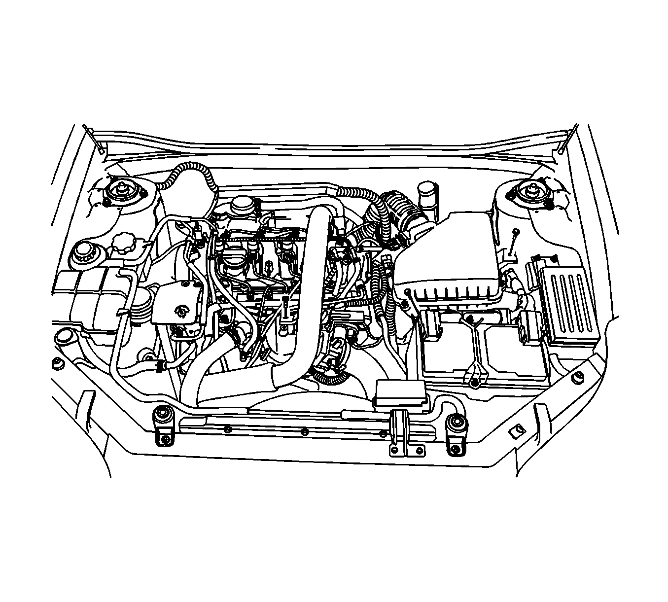
- Remove the engine cover. Refer to Engine Cover Replacement .
- Remove the charge air system hoses and ducts. Refer to Charge Air Cooler Inlet Pipe and Outlet Pipe Replacement .
- Remove the PCV valve and adapter. Refer to Positive Crankcase Ventilation Valve Replacement and Positive Crankcase Ventilation Hose/Pipe/Tube Replacement .
- Remove the fuel pipe-to-injector between the common rail and the injector. Refer to Fuel Injector Fuel Feed Pipe Replacement .
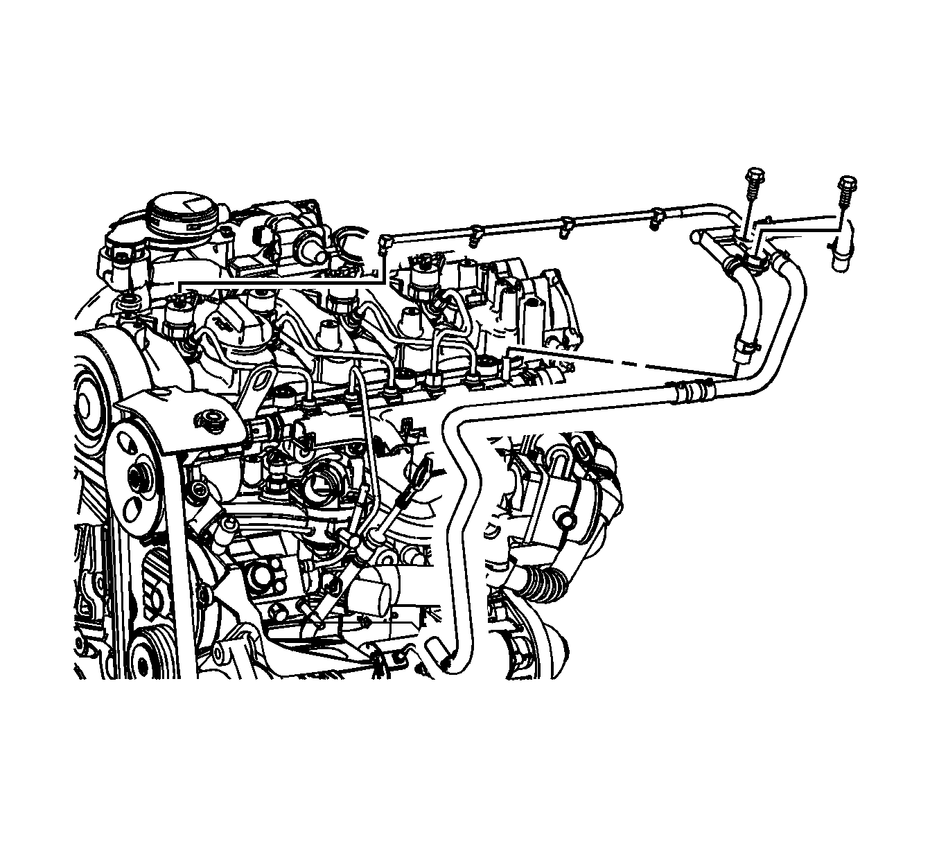
- Remove the fuel return line assembly. Refer to Fuel Return Pipe Replacement .
- Remove the timing belt upper cover.
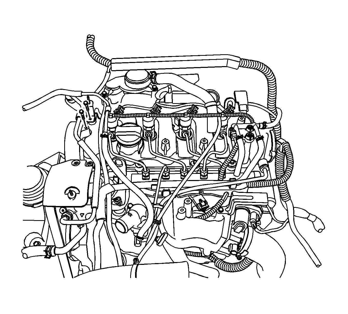
- Disconnect the CMP sensor connector.
- Remove the vacuum hose.
- Disconnect the fuel hose from the high pressure pump.
- Remove the brackets for retaining the power steering, fuel, and coolant hoses.
- Remove the injectors. Refer to Fuel Injector Replacement .
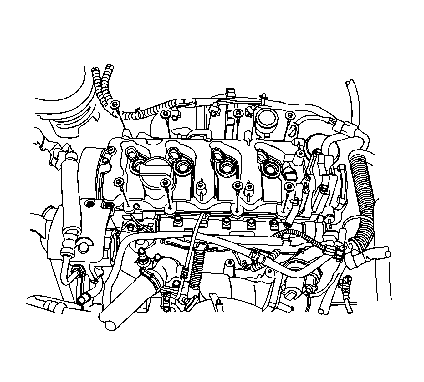
- Remove the cylinder head cover with the gasket.
Caution: Refer to Battery Disconnect Caution in the Preface section.
Cleaning Procedure
- Clean the cylinder head cover sealing surface.
- Clean the cylinder head sealing surface.
- Clean the cylinder head cover bolts.
- Clean the cylinder head cover bolt holes.
Installation Procedure
- Coat the sealant (LOCTITE 5900) on the camshaft front/rear cap surface.
- Install the cylinder head cover with a new gasket on the cylinder head.
- Install the timing belt upper cover.
- Install the fuel injector sight shield bracket with coolant return pipe to the surge tank.
- Install the fuel return line assembly.
- Install the fuel pipe-to-injector between the common rail and the injector. Refer to Fuel Injector Fuel Feed Pipe Replacement .
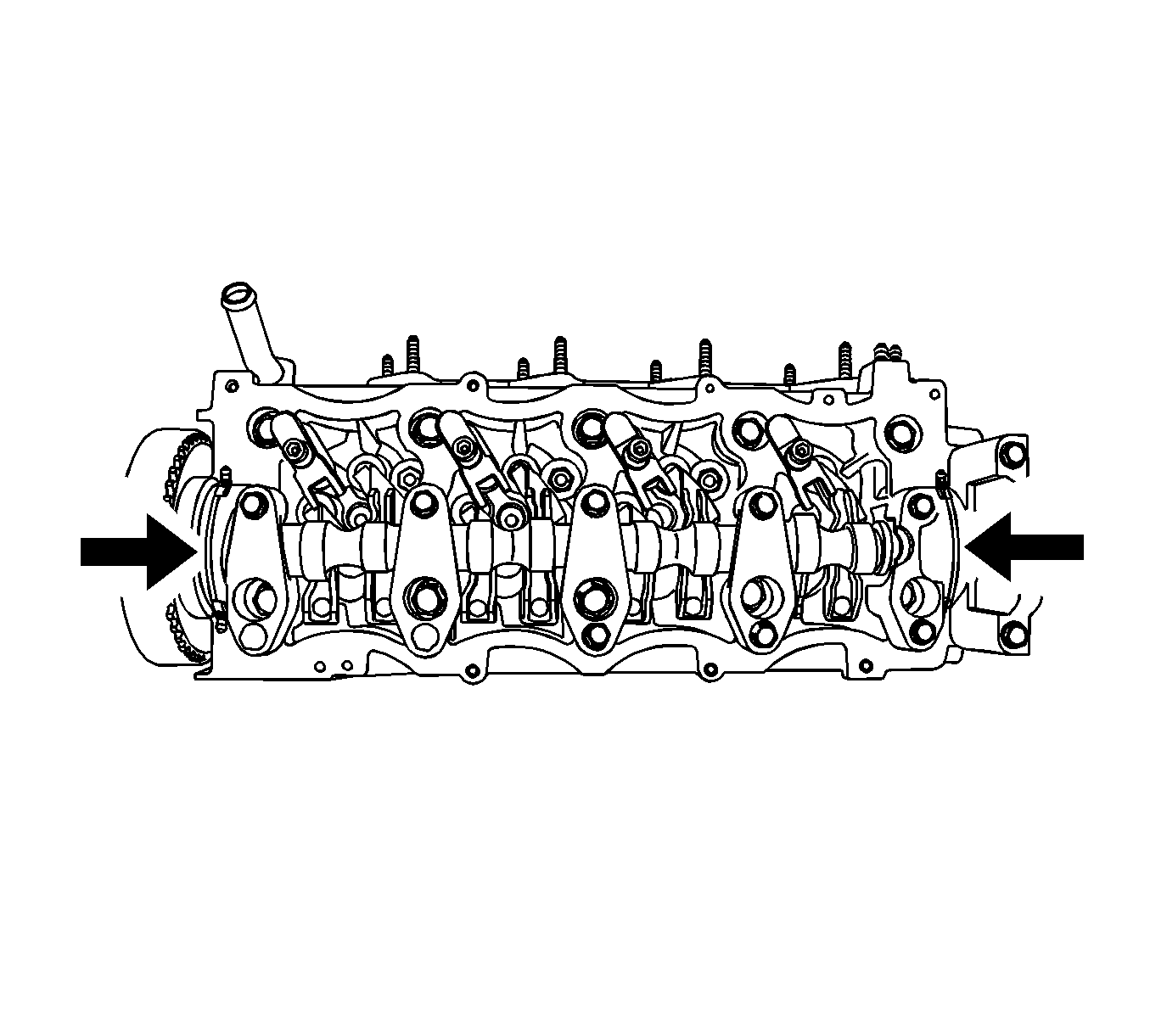
Notice: Refer to Fastener Notice in the Preface section.

Tighten
Tighten the cylinder head cover bolts to 12 N·m (8.9 lb ft).

Tighten
| • | Tighten the timing belt upper cover bolts to 11 N·m (97.4 lb in). |
| • | Tighten the coolant return pipe retaining bolt 9 N·m (79.7 lb in). |
| • | Tighten the junction block bolts to 11 N·m (97.4 lb in). |
| • | Tighten the fuel injector sight shield bracket bolt to 11 N·m (97.4 lb in). |
