Special Tools
| • | EN-48613 Engine Assembly Remove/Install Pallet |
| • | EN-48244 Engine Assembly Remove/Install Pallet Supporter |
Removal Procedure
- Discharge the air conditioning (A/C) system, if equipped.
- Drain the power steering oil, if equipped.
- Disconnect the negative battery cable.
- Remove the engine cover. Refer to Engine Cover Replacement.
- Remove the charge air system hoses and ducts. Refer to Charge Air Cooler Inlet Pipe and Outlet Pipe Replacement.
- Drain the engine coolant. Refer to Cooling System Draining and Filling.
- Disconnect the fuel hose from the high pressure pump.
- Remove the power steering pipe and hose.
- Disconnect the fuel return hose from the junction block.
- Remove the pipe and hose retaining bracket from the cylinder head cover.
- Disconnect the coolant by-pass hose from the intake manifold.
- Disconnect the radiator upper hose from the intake manifold.
- Disconnect the radiator lower hose from the engine block.
- Remove the engine wiring harness.
- Remove the surge tank. Refer to Radiator Surge Tank Replacement.
- Remove the right/left drive axle shaft.
- Remove the transaxle wiring harness.
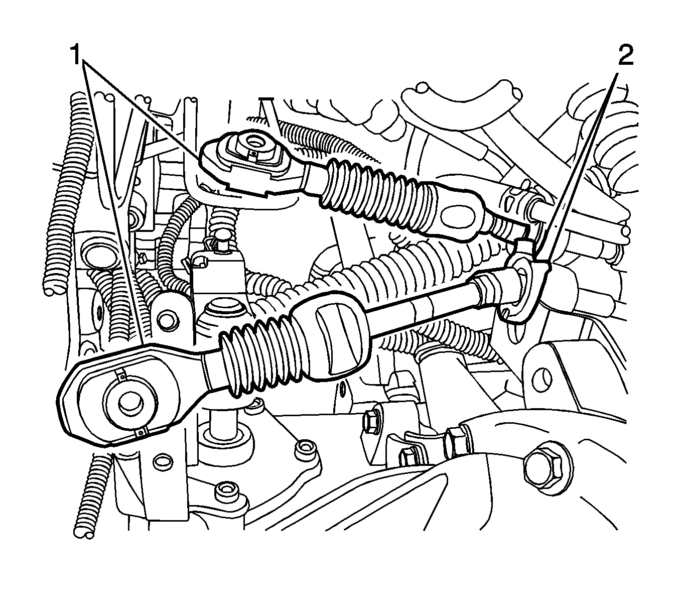
- Remove the shift control cable from the automatic transaxle.
- Remove the select cable from the transaxle.
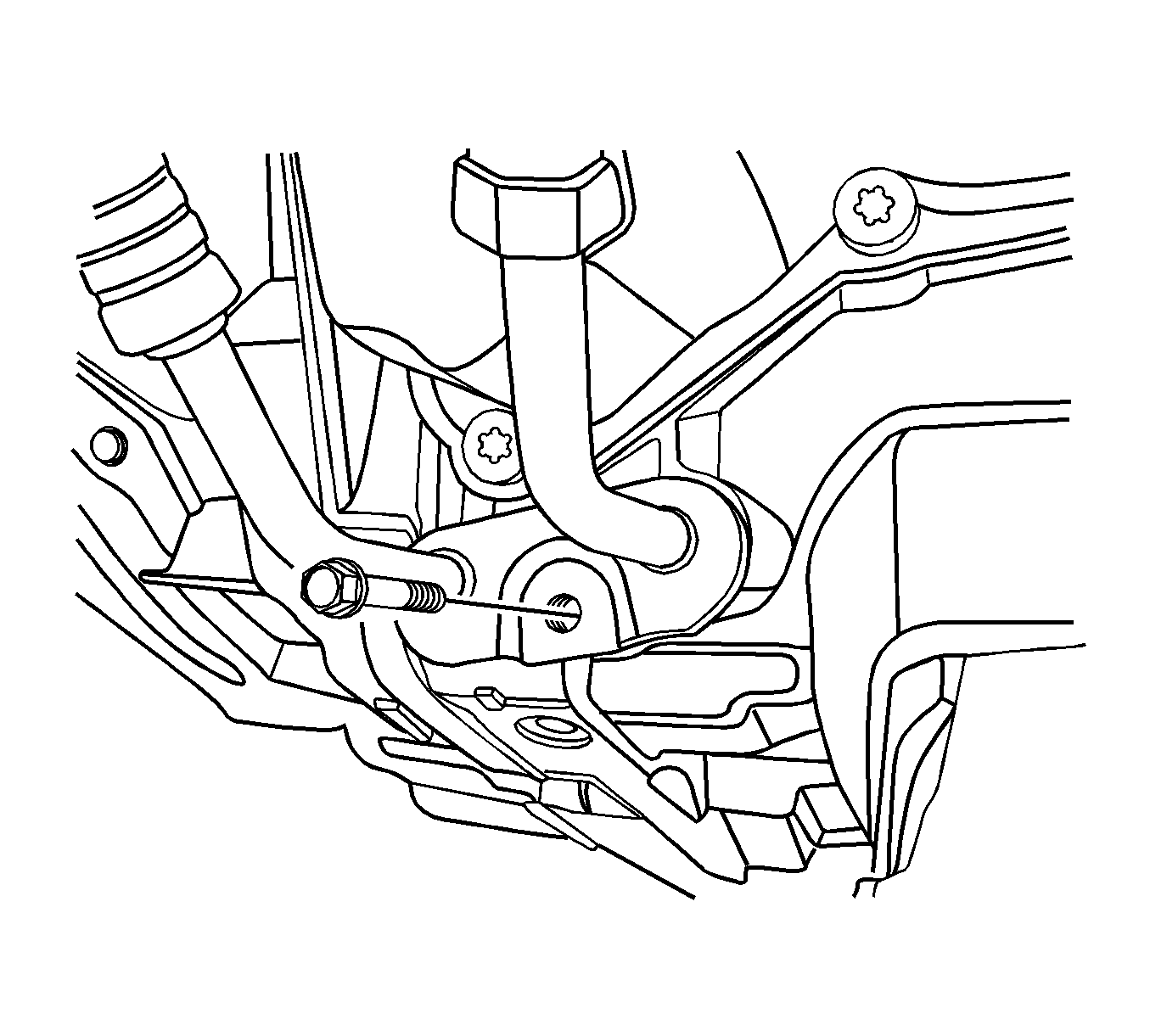
- Remove the transaxle oil cooler hoses from the automatic transaxle.
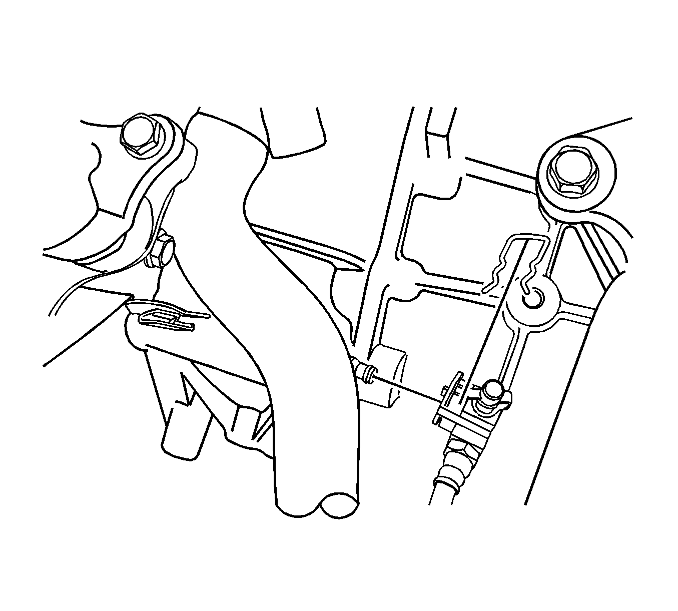
- Remove the clutch actuator cylinder pipe from the transaxle.
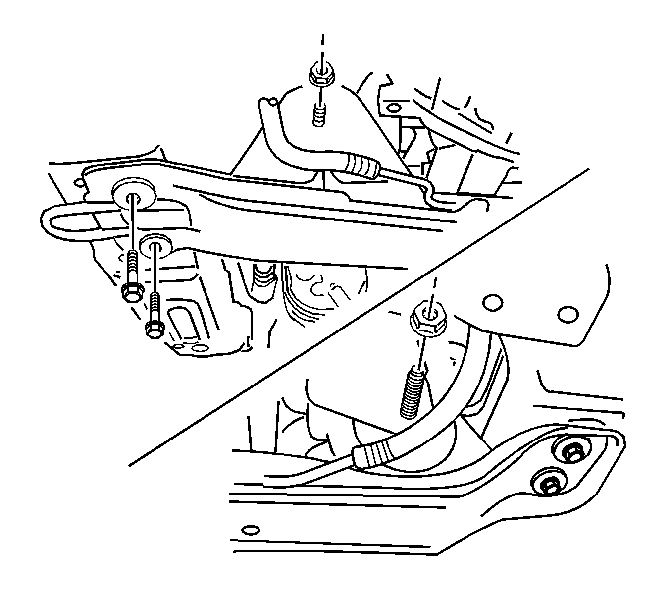
- Remove the centermember.
- Remove the front exhaust pipe between the pre-catalyst and the DPF pipe. Refer to Front Pipe Replacement.
- Remove the heater hoses.
- Remove the A/C compressor pipe from the compressor.
- Lower the vehicle and position the engine assembly onto the engine assembly. Remove/install pallet EN-48613 with the EN-48244 .
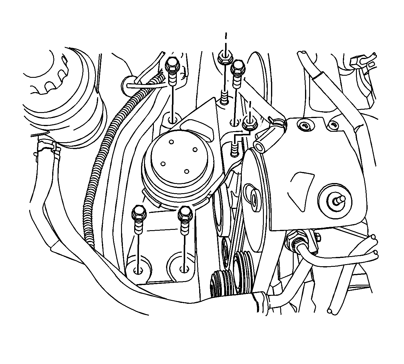
- Remove the engine mount. Refer to Engine Mount Replacement - Left Side.
- Remove the transaxle mount bolt from the transaxle.
- Remove the engine and transaxle.
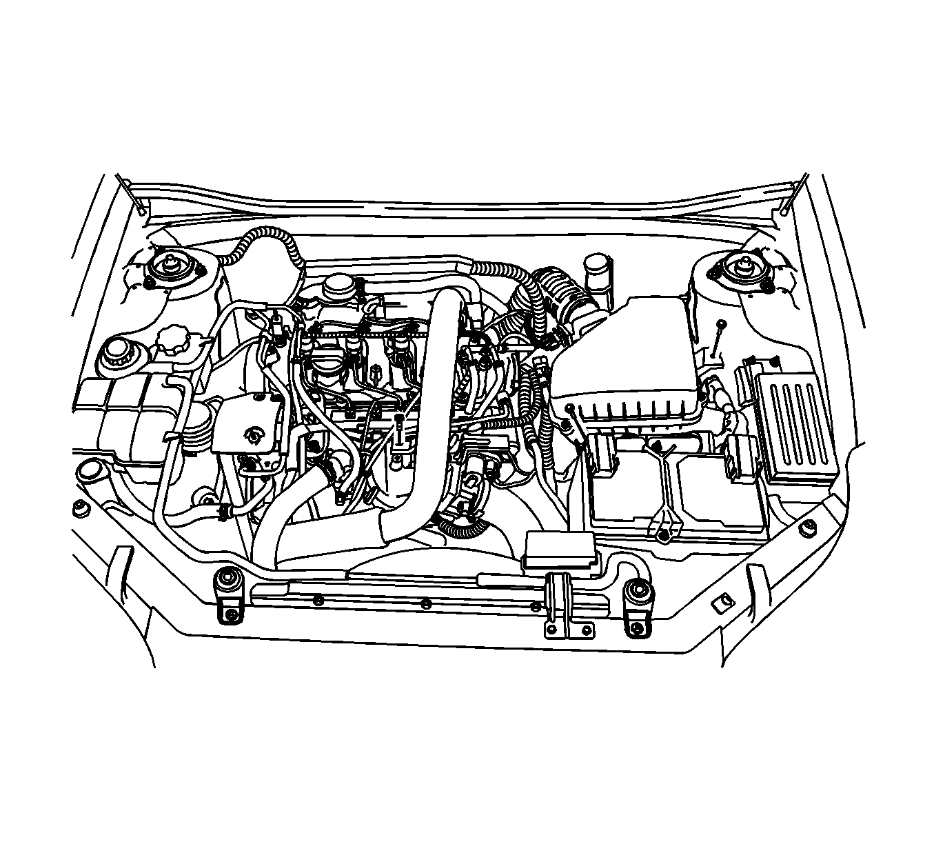
Caution: Refer to Battery Disconnect Caution in the Preface section.
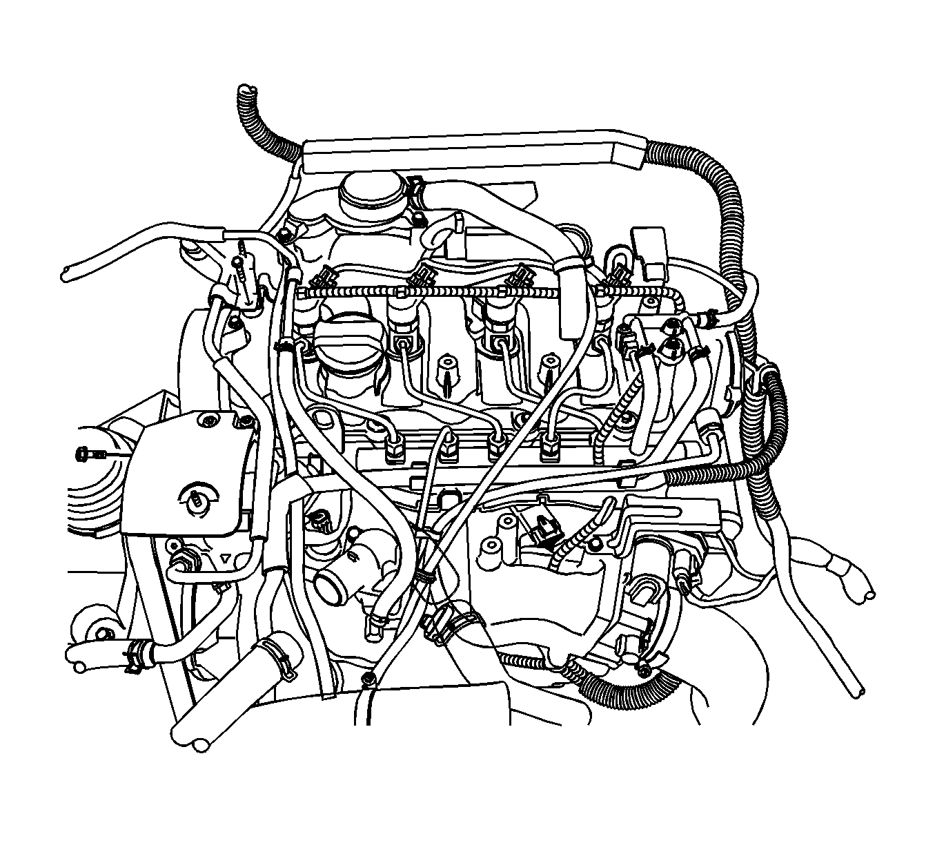
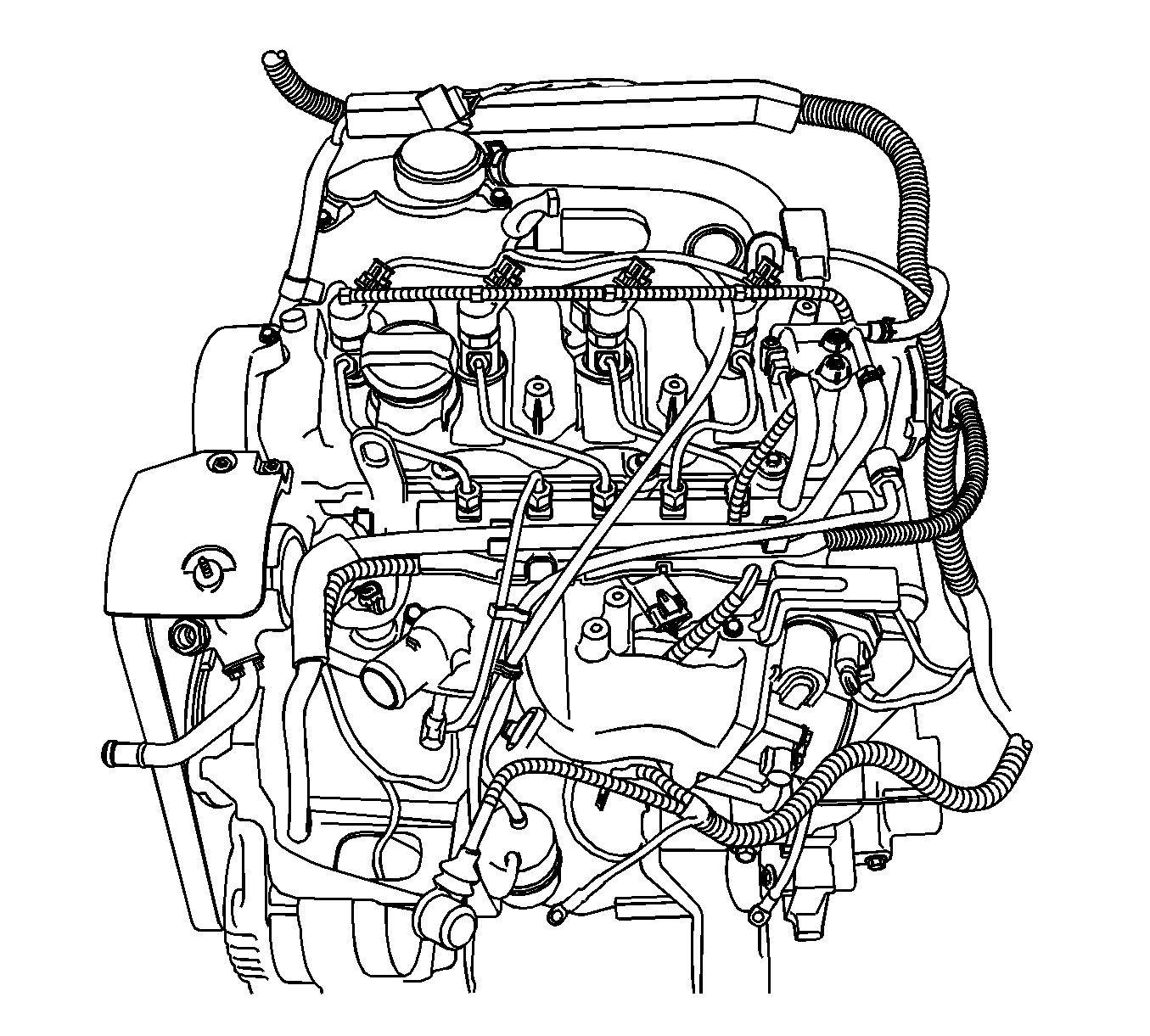
| • | Disconnect the injector connectors. |
| • | Disconnect the engine oil pressure switch connector. |
| • | Disconnect the high pressure pump connector. |
| • | Disconnect the alternator connector. |
| • | Disconnect the coolant temperature sensor (CTS) connector. |
| • | Disconnect the common rail pressure sensor connector. |
| • | Disconnect the electronic throttle control (ETC) connector. |
| • | Disconnect the EGR vacuum solenoid connector. |
| • | Disconnect the A/C compressor connector. |
| • | Disconnect the camshaft position sensor (CMP) connector. |
| • | Disconnect the turbocharger actuator connector. |
| • | Disconnect the glow plug wire connector. |
| • | Disconnect the booster pressure (T-MAP) sensor connector. |
| • | Disconnect the common rail regulator connector. |
| • | Disconnect the starter solenoid wiring connector. |
| • | Disconnect the crankshaft position sensor. |
| • | Remove the glow plug fuse box. |
| • | Remove the generator B+ connector nut. |
| • | Remove the starter solenoid connector nut. |
| • | Remove the engine ground bolt. |
| • | Remove the transaxle ground bolt. |
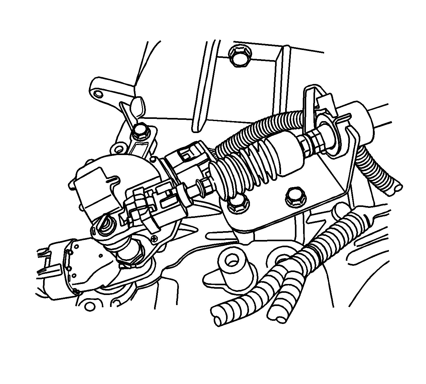
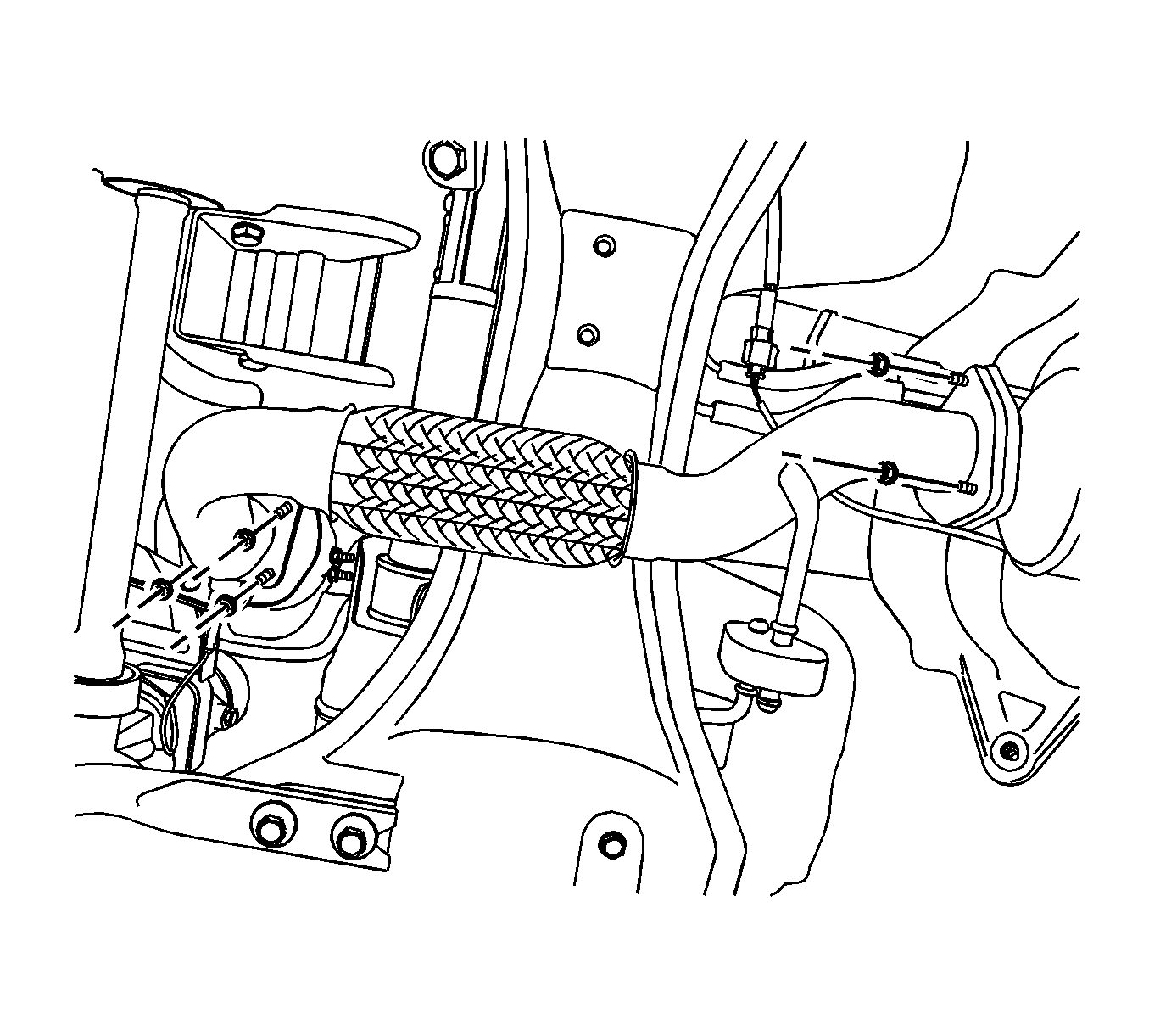
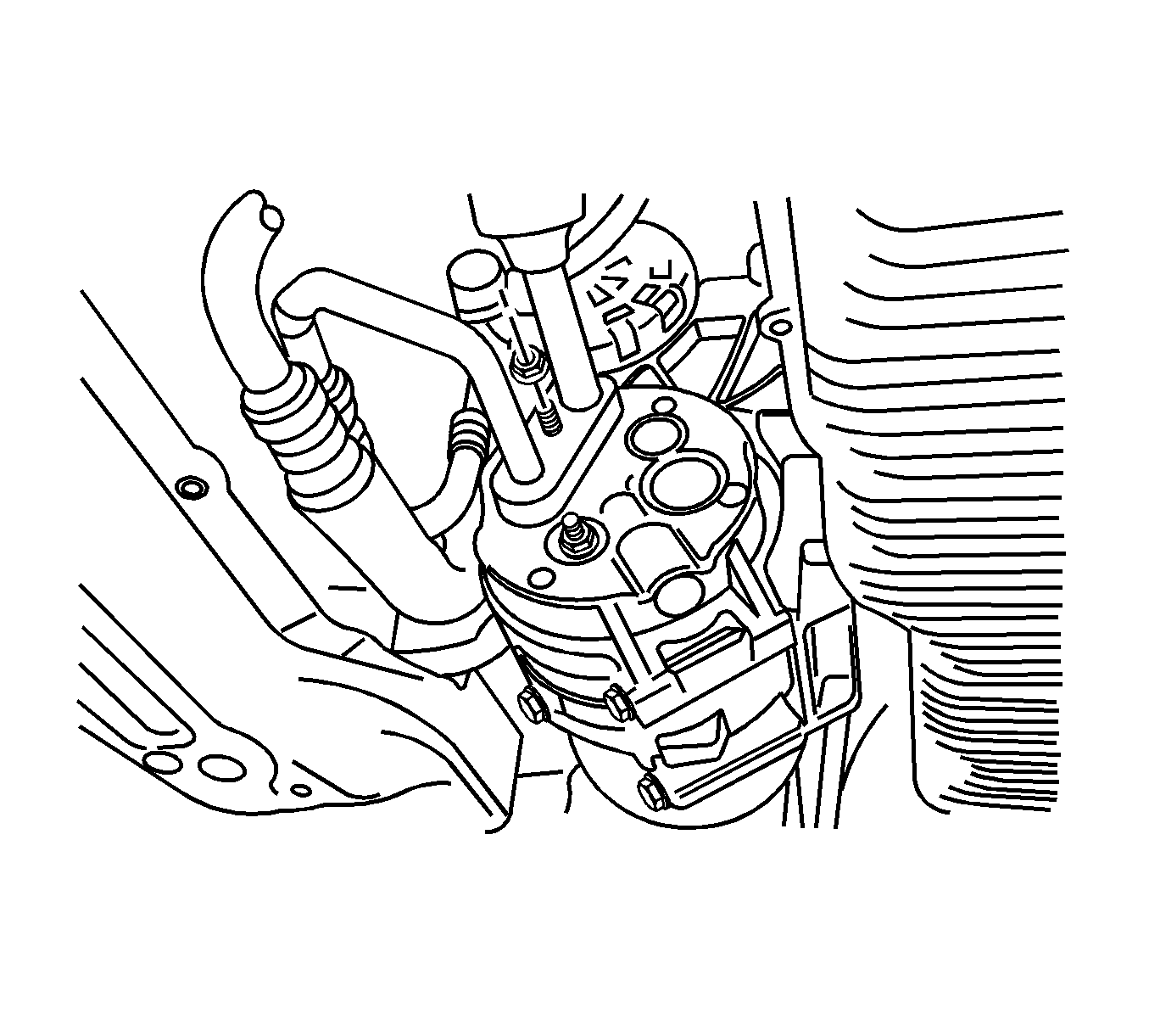
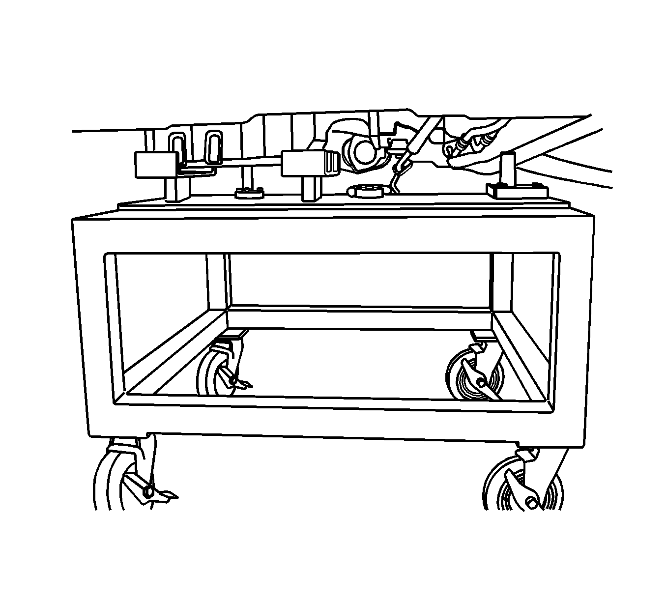
Important: Only lower the vehicle far enough to take the weight off the engine and transaxle mount, or damage to the mount and pallet/pallet support failure may occur.
Installation Procedure
- Install the transaxle to the engine assembly.
- Install engine assembly to the vehicle by using the remove/install pallet EN-48613 with the EN-48244 .
- Install the transaxle mount bolts.
- Install the engine mount bolt.
- Remove EN-48613 with the EN-48244 from the vehicle.
- Install the engine wiring harness.
Notice: Refer to Fastener Notice in the Preface section.

Tighten
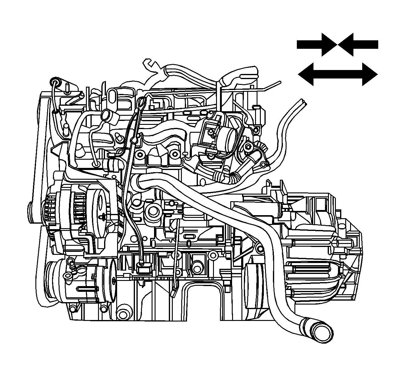
| • | Tighten the transaxle tightening bolts to 75 N·m (55.3 lb ft). |
| • | Tighten the oil pan flange-to-transaxle bolts to 50 N·m (36.9 lb ft). |

Tighten
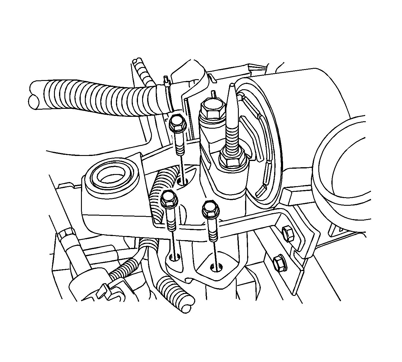
Tighten the transaxle mount bracket retaining bolts (1) to 40 N·m (30 lb ft).

Tighten
Tighten the engine mount bracket retaining bolt to 65 N·m (47.9 lb ft).

| • | Connect the injector connectors. |
| • | Connect the engine oil pressure switch connector. |
| • | Connect the high pressure pump connector. |
| • | Connect the alternator connector. |
| • | Connect the coolant temperature sensor (CTS) connector. |
| • | Connect the common rail pressure sensor connector. |
| • | Connect the electronic throttle control (ETC) connector. |
| • | Connect the EGR vacuum solenoid connector. |
| • | Connect the A/C compressor connector. |
| • | Connect the camshaft position sensor (CMP) connector. |
| • | Connect the turbocharger actuator connector. |
| • | Connect the glow plug wire connector. |
| • | Connect the booster pressure (T-MAP) sensor connector. |
| • | Connect the common rail regulator connector. |
| • | Connect the starter solenoid wiring connector. |
| • | Connect the crankshaft position sensor. |
| • | Install the glow plug fuse box. |
Tighten
Tighten the glow plug fuse box bolts to 10 N·m (88.5 lb in).
| • | Install the generator B+ connector nut. |
Tighten
Tighten the generator B+ connector nut to 25 N·m (18.4 lb ft).
| • | Install the starter solenoid connector nut. |
Tighten
Tighten the starter solenoid connector nut to 15 N·m (11.1 lb ft).
| • | Install the engine ground bolt. |
Tighten
Tighten the engine block ground bolt to 25 N·m (18.4 lb ft).
| • | Install the transaxle ground bolt. |
Tighten
Tighten the transaxle ground bolt to 25 N·m (18.4 lb ft).
