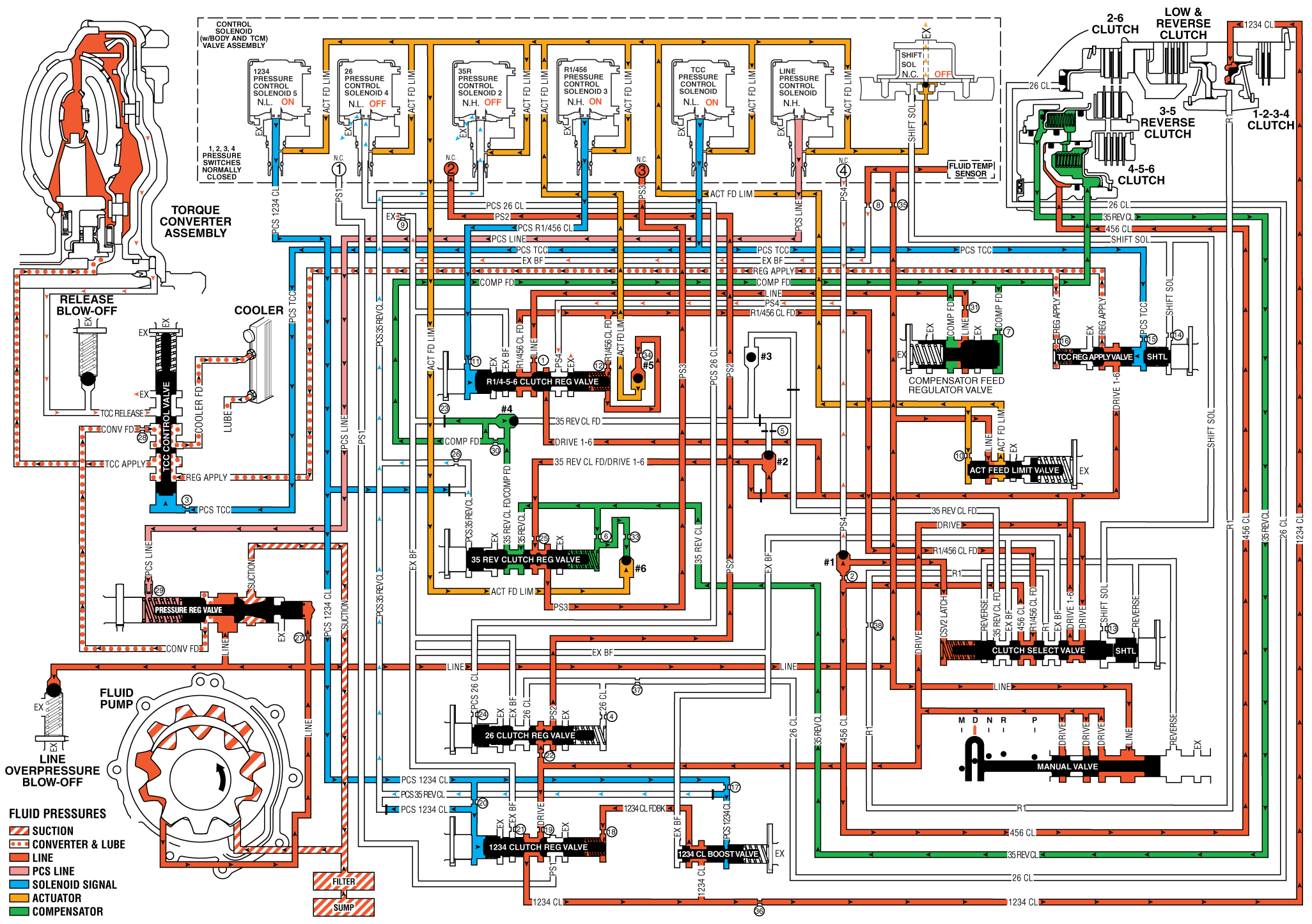
As the vehicle speed increases, the transmission control module (TCM) receives input signals from the automatic transmission input and output speed sensors, the throttle position sensor and other vehicle sensors to determine the precise moment to command OFF the normally-high 35R pressure control solenoid 2. At the same time the normally-low R1/456 pressure control solenoid 3 is commanded ON to regulate 4-5-6 clutch apply.
4-5-6 Clutch Applies
R1/456 Pressure Control Solenoid 3
The R1/456 pressure control solenoid 3 (PCS) is commanded ON allowing actuator feed fluid to enter the PCS R1/456 clutch fluid circuit. PCS R1/456 clutch fluid is routed through orifice #11 to the R1/456 clutch regulator valve.
R1/456 Clutch Regulator Valve
PCS R1/456 clutch fluid moves the R1/456 clutch regulator valve against R1/456 clutch regulator valve spring force and R1/456 clutch feed fluid. This allows R1/456 feed to pass through the valve and enter the R1/456 clutch circuit. R1/456 clutch fluid is then routed through orifice #12 to the spring area of the R1/456 clutch regulator valve and through orifice #34 to ball check valve 5. R1/456 clutch feed fluid enters the clutch select valve where it enters the 456 clutch feed circuit. 456 clutch fluid passes through orifice #2 seating ball check valve #1 against the PS4 fluid circuit. When the R1/456 clutch regulator valve is in this position, PS4 fluid from the pressure switch 4 exhausts through the valve, allowing the switch to close.
#1 Ball Check Valve
The 456 clutch fluid pressure seats #1 ball check valve against the PS4 fluid circuit to force fluid through orifice #2 and applies the 456 clutch.
4-5-6 Clutch
The 4-5-6 clutch fluid enters the 3-5 reverse/456 clutch housing to move the piston against spring force to apply the 4-5-6 clutch plates.
3-5 Reverse Clutch Releases
35R Pressure Control Solenoid 2
The 35R pressure control solenoid 2 is commanded OFF, allowing PCS 35 reverse clutch fluid from the 3-5 reverse clutch regulator valve to exhaust through the solenoid.
3-5 Reverse Clutch Regulator Valve
The 3-5 reverse clutch regulator valve spring force moves the valve to allow 35 reverse clutch fluid from the 3-5 reverse clutch to pass through the valve and enter the exhaust backfill fluid circuit. The 35 reverse clutch fluid then enters the exhaust backfill fluid circuit and is routed through orifice #30 to the compensator feed fluid circuit. 35 reverse feed/Drive 1-6 fluid passes through orifice #25 and enters the PS2 circuit. PS2 fluid is then routed to pressure switch 3 and opens the normally-closed switch.
3-5 Reverse Clutch
The 3-5 reverse clutch spring force combined with force from the compensator move the 3-5 reverse clutch piston to release the 3-5 clutch plates and forces 35 reverse clutch fluid to exhaust from 3-5 reverse/456 clutch housing. The 35 reverse clutch fluid is then routed to the 3-5 reverse clutch regulator valve and enters the exhaust backfill fluid circuit.
#1 Ball Check Valve
The 456 clutch fluid pressure passes through orifice #2 to seat #1 ball check valve against PS4 fluid passage. The 456 clutch fluid is then directed into the CSV2 latch circuit.
Torque Converter Clutch Applies
TCC Pressure Control Solenoid
The torque converter clutch (TCC) pressure control solenoid is commanded ON, allowing PCS TCC fluid to enter the PCS TCC fluid circuit. PSC TCC fluid is routed through orifice #15 to the TCC regulator apply valve and through orifice #3 to the TCC control valve.
TCC Regulator Apply Valve
PCS TCC fluid moves the TCC regulator apply valve against TCC regulator apply valve spring force and allows drive 1-6 fluid to pass through the valve into the regulator apply fluid circuit. Regulator apply fluid circuit is routed to the TCC control valve and through orifice #16 to the spring area of the TCC regulator apply valve.
TCC Control Valve
PCS TCC fluid moves the TCC control valve against TCC control valve spring force and allows regulator apply fluid to pass through the valve into the TCC apply fluid circuit to apply the torque converter clutch. Converter feed fluid passes through orifice #28 to the TCC control valve and enters the cooler feed circuit. TCC release fluid passes through the TCC control valve and is exhausted.
Drive Range, Fourth Gear Default (some models)
The transmission default gear could be 4th or 5th gear based on engine size and effective final drive ratio. If the transmission encounters an electrical component failure, the transmission will default to 4th gear. All solenoids will default to their normal state. If the torque converter clutch was applied, it will release. The transmission will stay in 4th gear default range until the ignition has been turned off or transmission is shifted to reverse. This default action will enable the vehicle to be safely driven to a service center.
Drive Range, Fourth Gear

