For 1990-2009 cars only
Removal Procedure
- Disconnect the negative battery cable.
- Remove the instrument panel (IP) assembly. Refer to Instrument Panel Assembly Replacement .
- Drain the cooling system. Refer to Cooling System Draining and Filling .
- Recover the refrigerant. Refer to Refrigerant Recovery and Recharging .
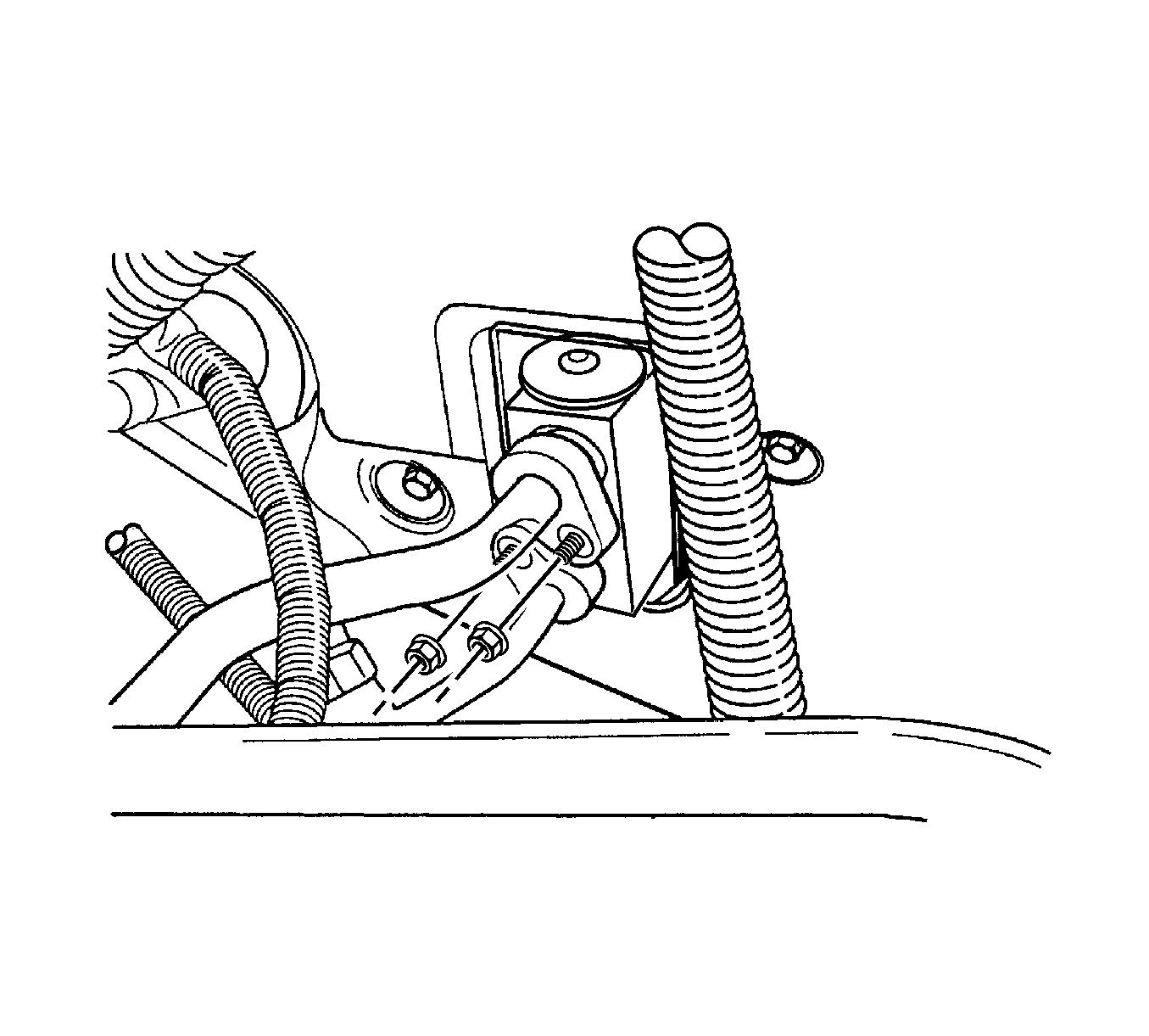
- Remove the retaining nuts that secure the suction hose and the liquid evaporator pipe blocks at the cowl.
- Loosen the clamp bolts from the suction hose and the liquid evaporator pipe to allow movement of the hose and the pipe.
- Remove the evaporator drain hose.
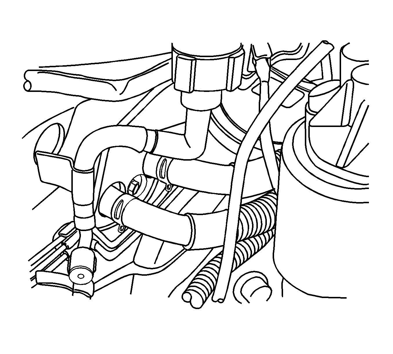
- Compress the heater hose clamps at the cowl and slide the clamps toward the engine.
- Remove the 2 heater hoses from the core lines at the cowl.
- Remove the screws that secure the HVAC module to the cowl on either side of the heater hoses.
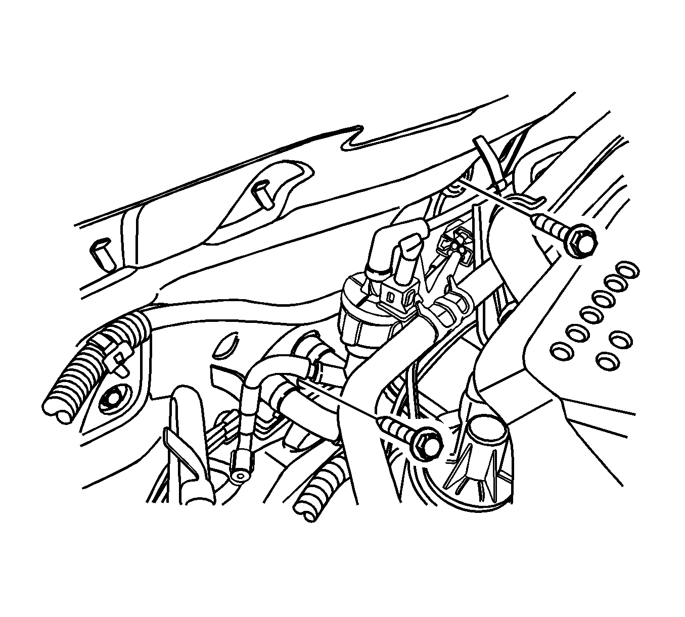
- Remove the HVAC module screw, that is located above the fuel filter, from the engine compartment side of the cowl.
- Have an assistant support the HVAC module from inside the vehicle.
- Remove the HVAC module screws from the evaporator flange on the engine compartment side of the cowl. The HVAC module will start to drop.
- Pull the case straight away from the cowl.
- Remove the HVAC module from the vehicle.
Caution: Refer to Battery Disconnect Caution in the Preface section.
Installation Procedure
- Position the HVAC module in the vehicle.
- Slowly raise the HVAC module into position and hold it against the cowl while the screws are installed and tightened from the engine side of the cowl.
- Align and install the HVAC module screws above the fuel filter and at the evaporator flange.
- Install the HVAC module screws adjacent to the heater hoses.
- Install the evaporator drain hose.
- Install the 2 heater hoses.
- Slide the heater hose clamps into position.
- Install the instrument panel (IP) assembly. Refer to Instrument Panel Assembly Replacement .
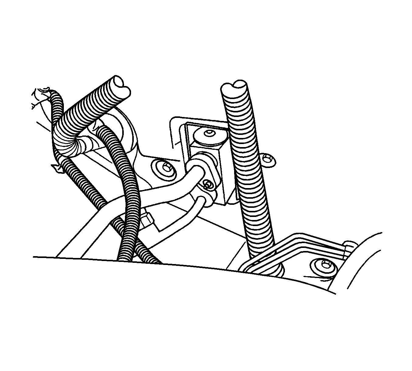
- Install new O-rings on the suction hose and the liquid evaporator pipe at the cowl and put the pipes back in place.
- Install the retaining nuts that secure the suction hose and the liquid evaporator pipe blocks at the cowl.
- Fill the cooling system. Refer to Cooling System Draining and Filling .
- Recharge the A/C system. Refer to Refrigerant Recovery and Recharging .
- Connect the negative battery cable.

Important: To avoid damaging the heater core tubes, make sure they do not contact the cowl opening.
Notice: Refer to Fastener Notice in the Preface section.
Tighten
Tighten the HVAC module screws to 4 N·m (35 lb in).
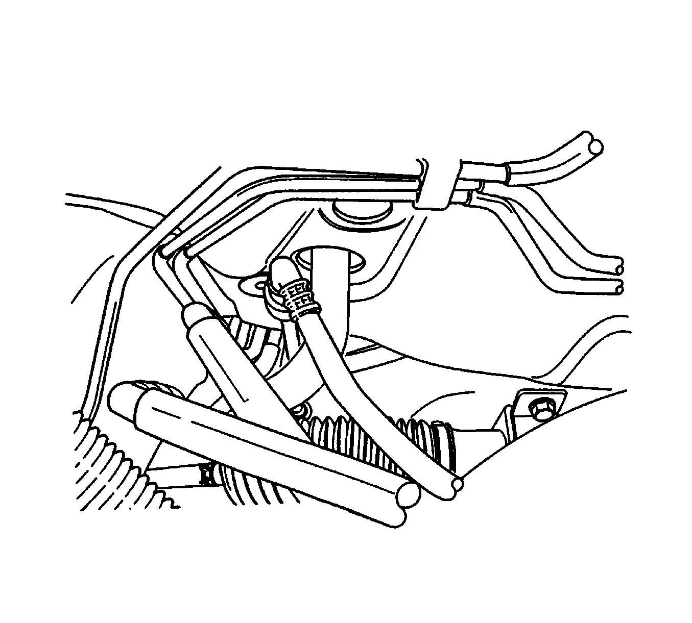
Tighten
Tighten the HVAC module screws to 4 N·m (35 lb in).
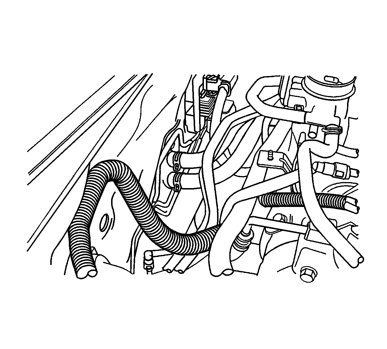

Tighten
Tighten the suction hose and the liquid evaporator pipe retaining nuts to 10 N·m (89 lb in).
