For 1990-2009 cars only
Removal Procedure
- Remove the fuel pump fuse.
- Start the engine and repeat cranking until the remaining fuel in the fuel line is all consumed.
- Disconnect the negative battery cable.
- Drain the engine coolant. Refer to Cooling System Draining and Filling.
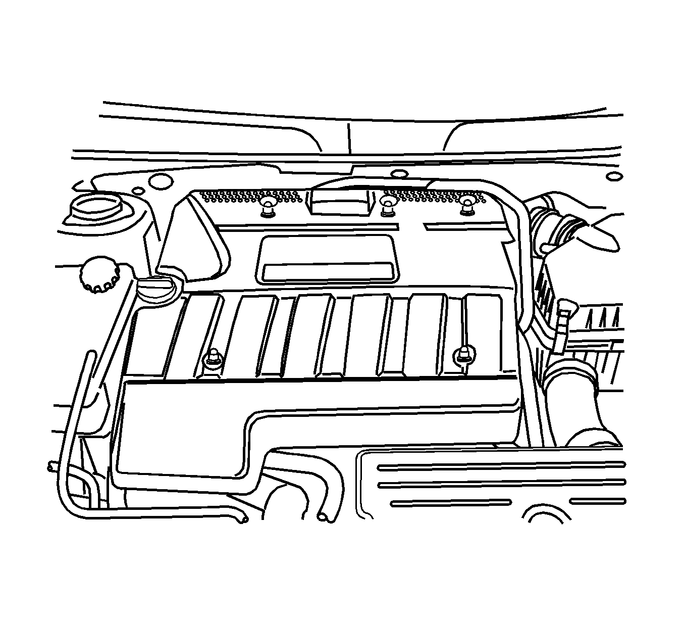
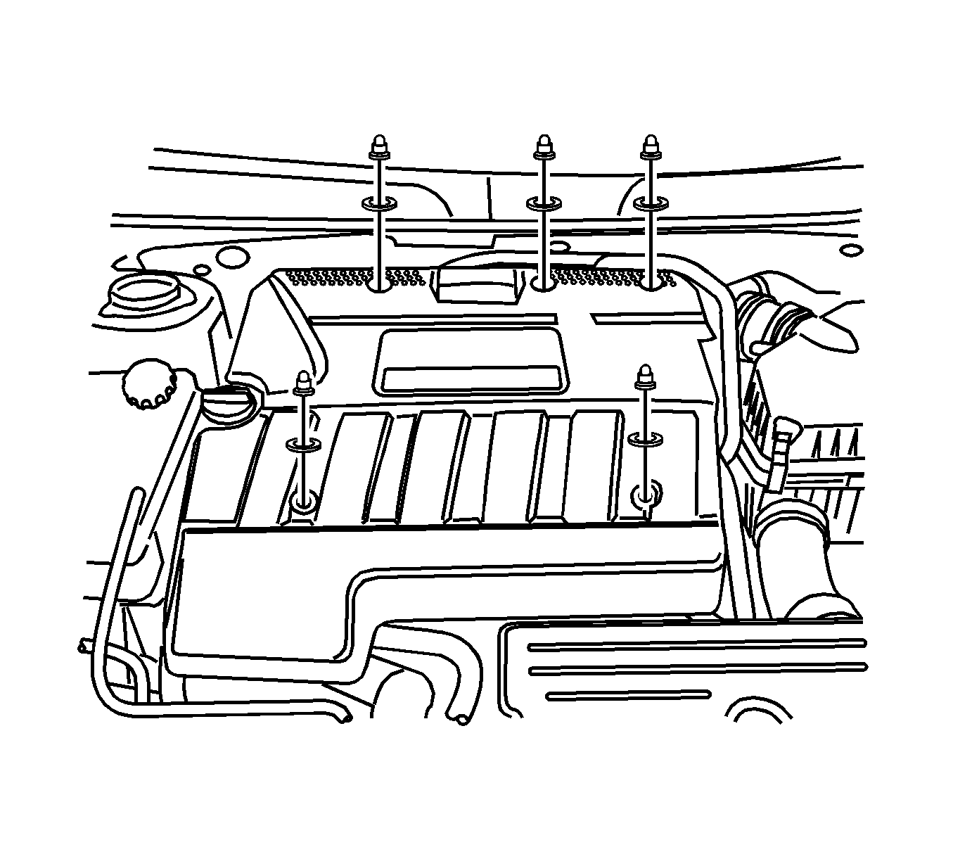
- Remove the engine beautification cover retaining nut and engine beautification cover.
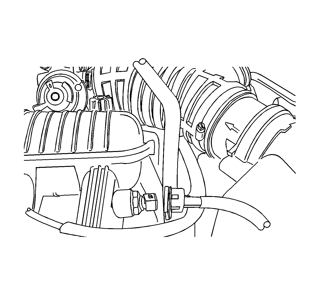
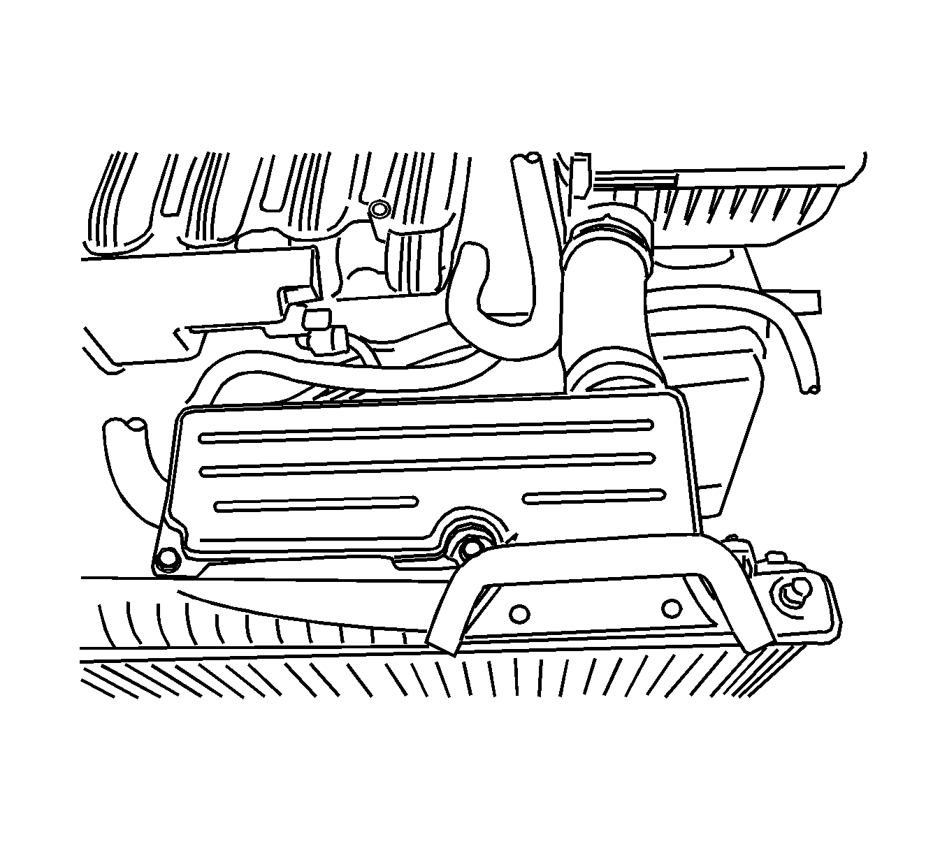
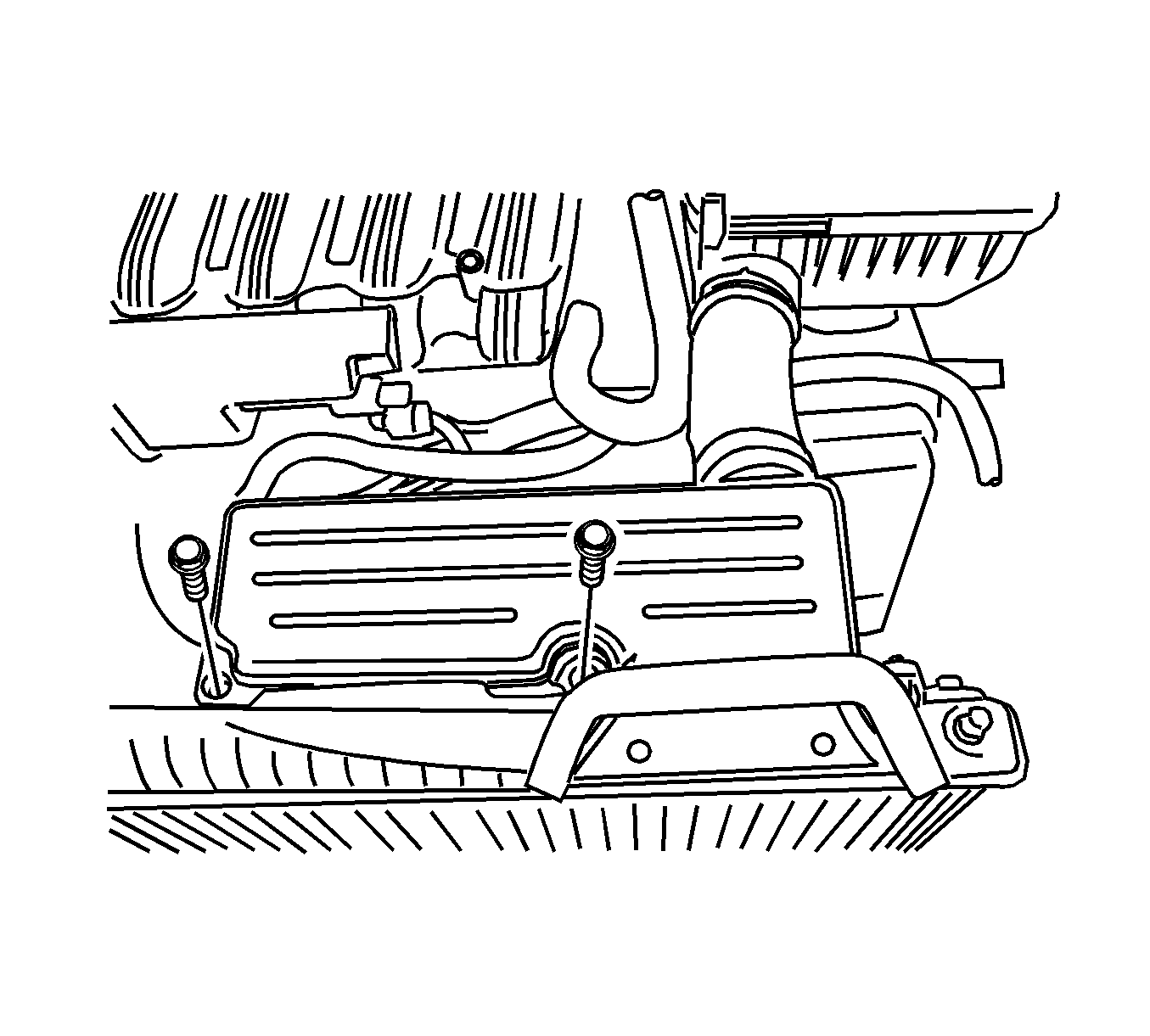
- Remove the air filter snorkel.
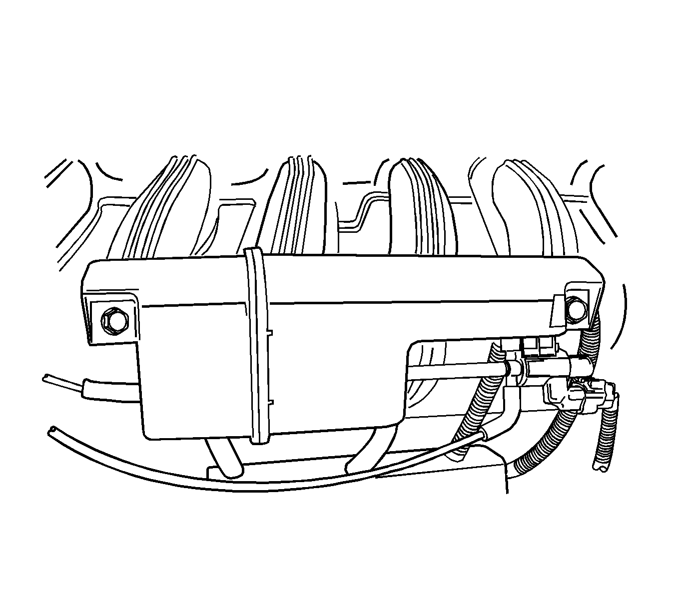
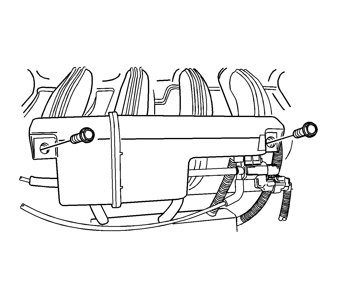
- Remove the variable intake system (VIS) vacuum tank.
- Remove the fuel pressure regulator.
- Remove the breather hose.
- Remove the positive crankcase ventilation (PCV) vacuum hose.
- Remove the air filter outlet hose.
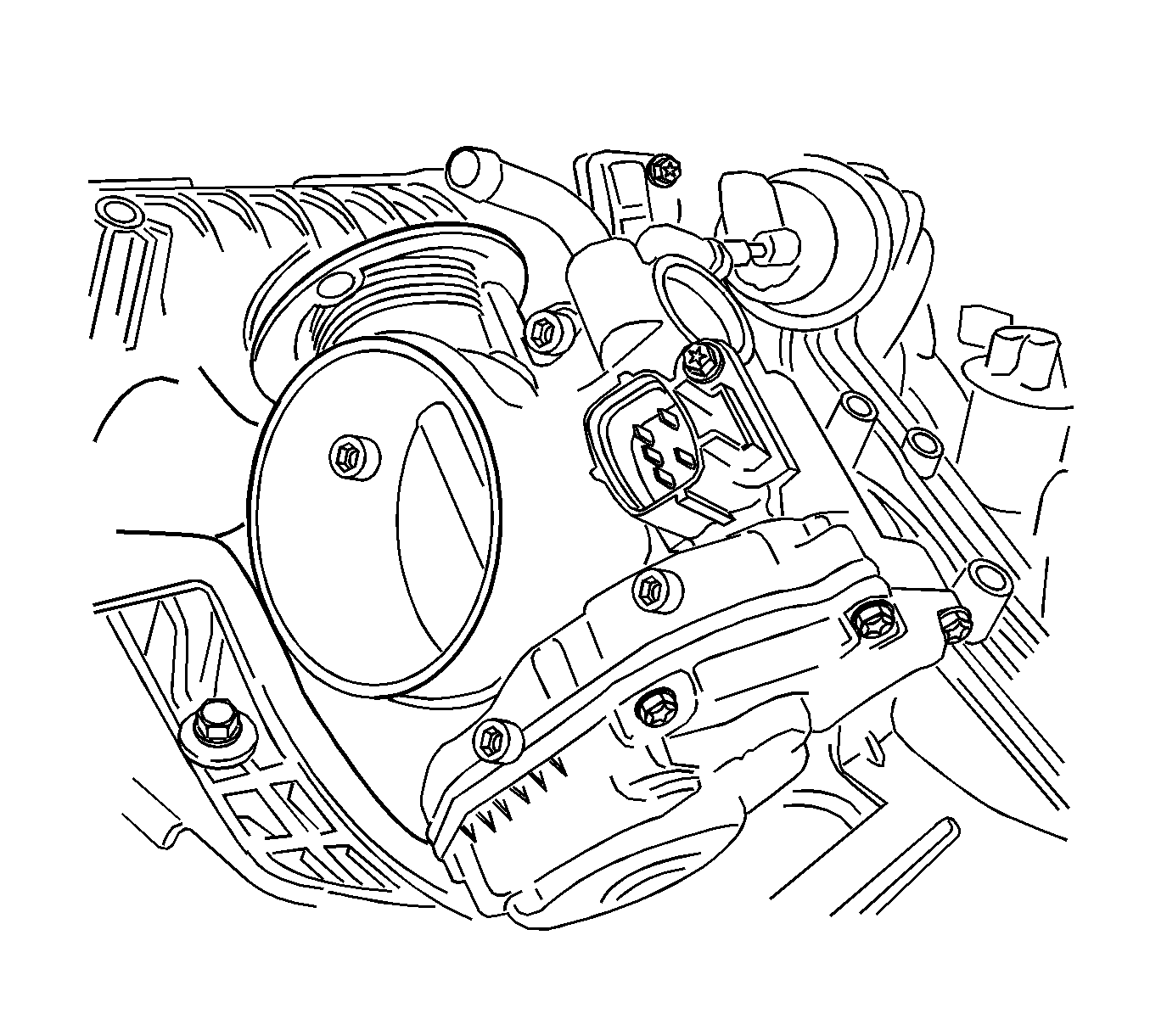
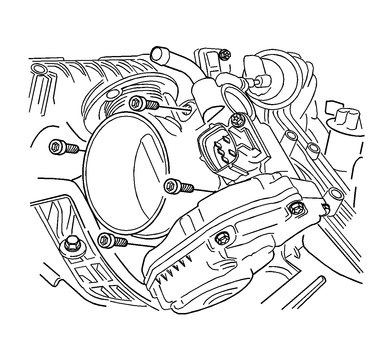
- Remove the throttle body assembly. Refer to Throttle Body Assembly Replacement.
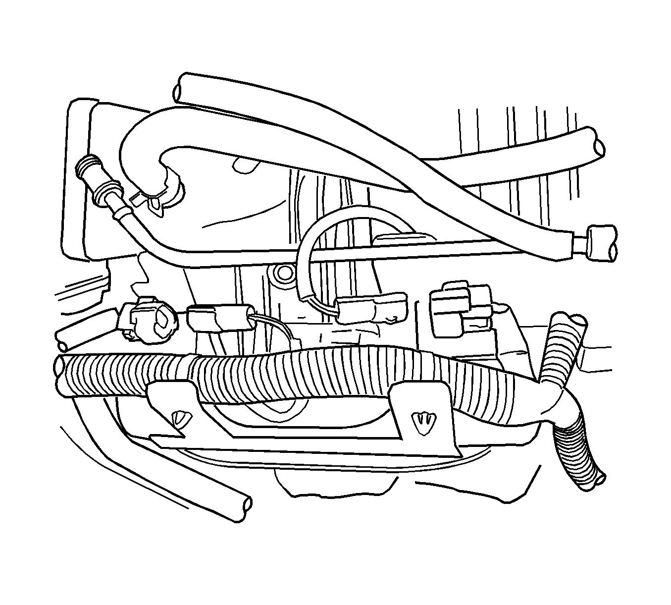
- Disconnect the charcoal canister purge solenoid connector and hose.
- Disconnect the heated oxygen sensor (HO2S) connector.
- Disconnect the manifold absolute pressure (MAP) sensor connector.
- Disconnect the crankshaft position (CKP) sensor connector.
- Disconnect the exhaust gas recirculation (EGR) solenoid connector.
- Disconnect the camshaft position (CMP) sensor connector.
- Remove the intake air temperature (IAT) sensor.
- Disconnect the ignition coil connector.
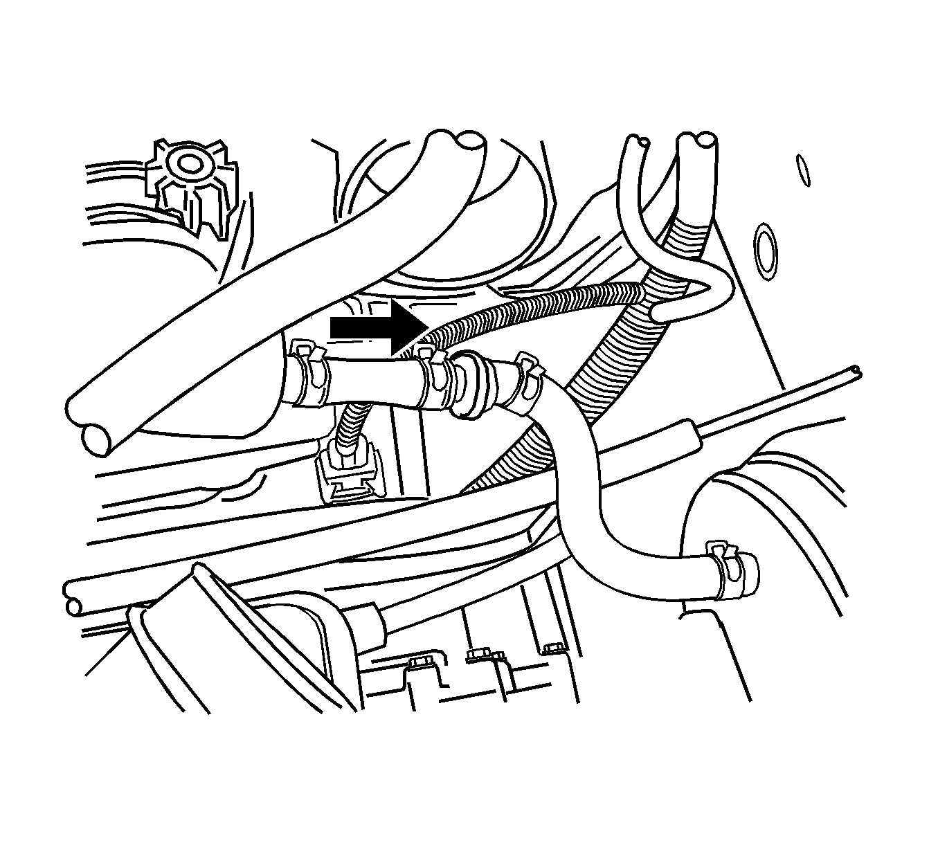
- Remove the vacuum hose on the brake booster.
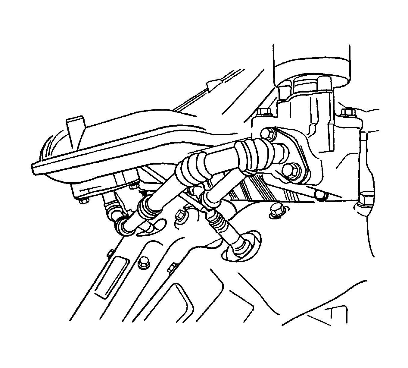
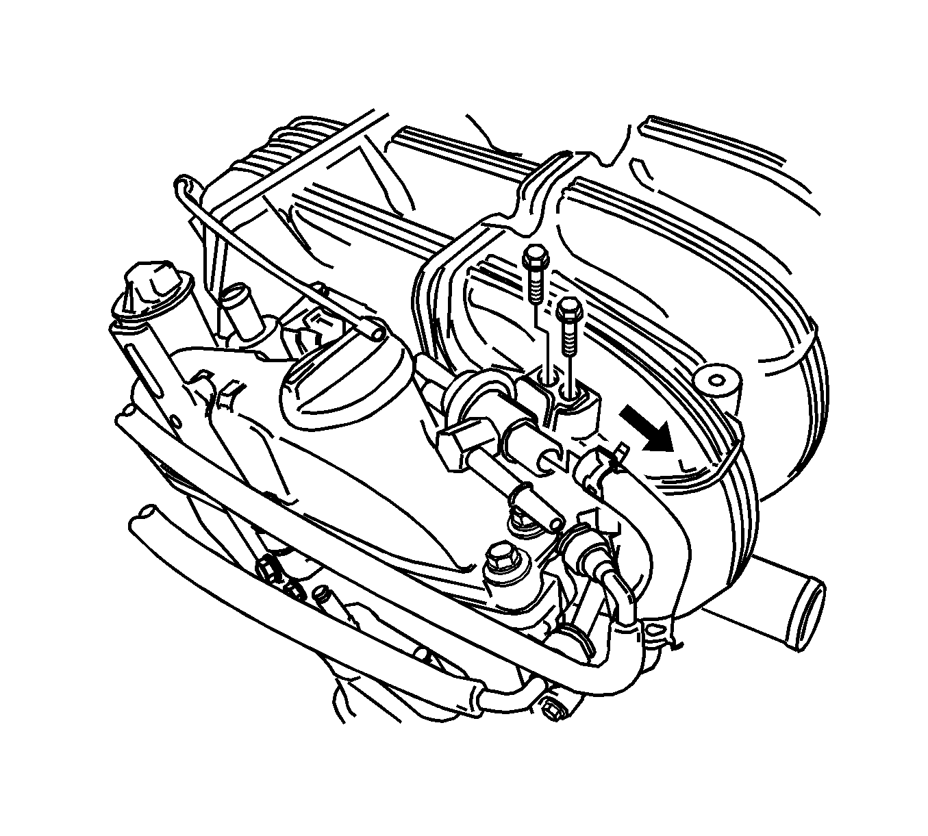
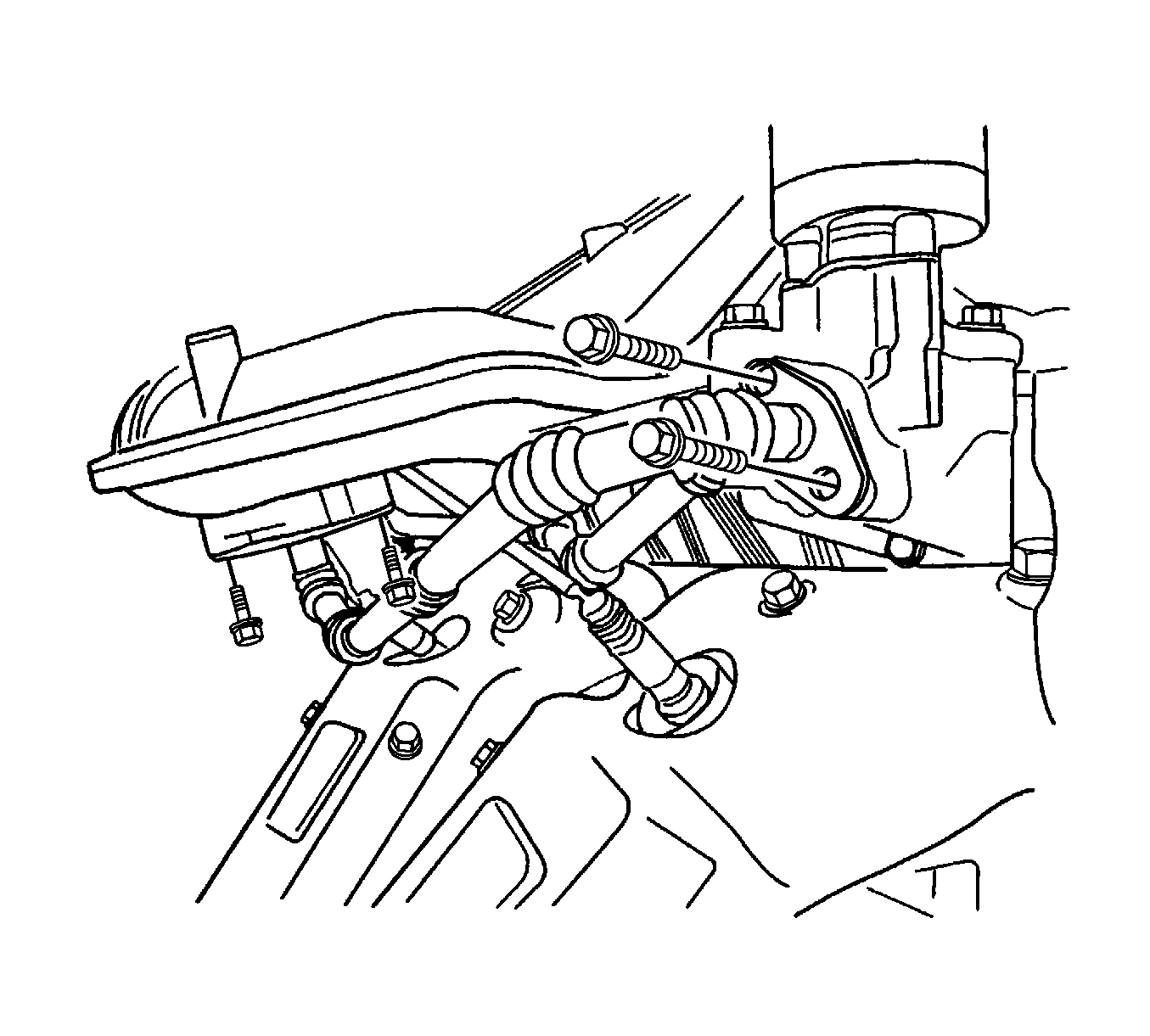
- Remove the EGR pipe from the intake manifold.
- Remove the engine coolant temperature (ECT) sensor.
- Remove the wiring harness from the support bracket on the cylinder block.
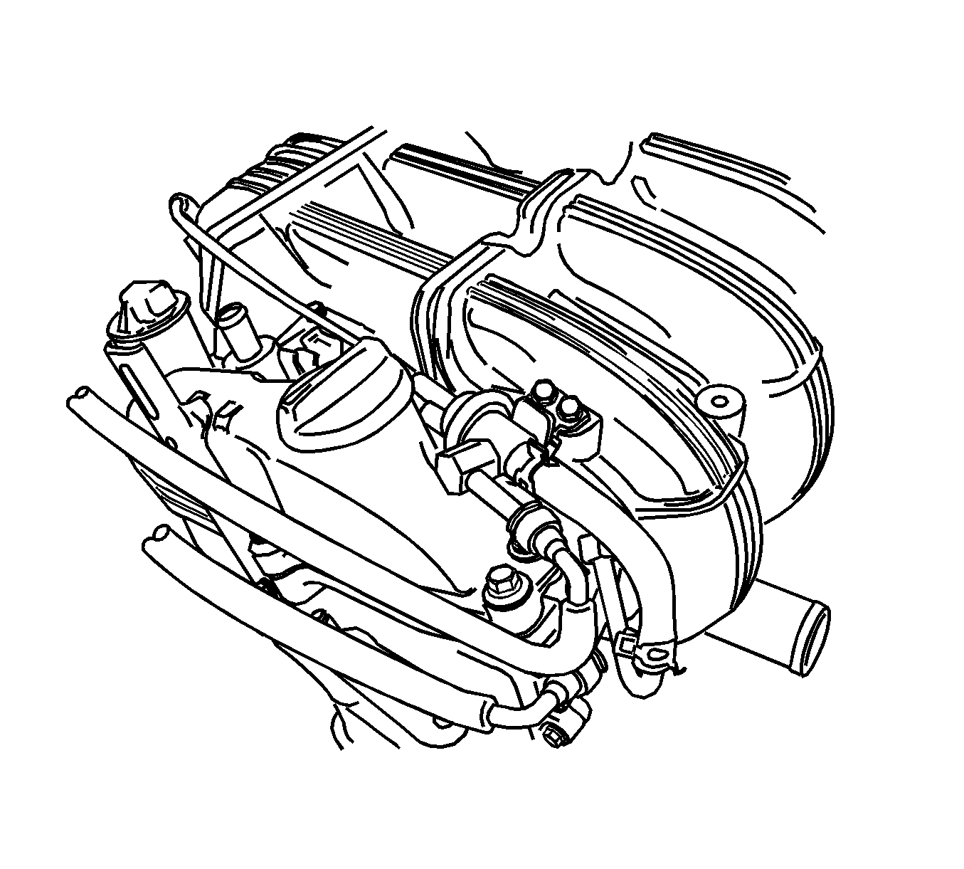
- Remove the intake manifold retaining nuts/bolts and the intake manifold.
- Remove the bolts on the intake manifold support bracket.
- Remove the intake manifold gaskets.
- Clean the contact surfaces between intake manifold and the cylinder head.
Warning: Refer to Battery Disconnect Warning in the Preface section.
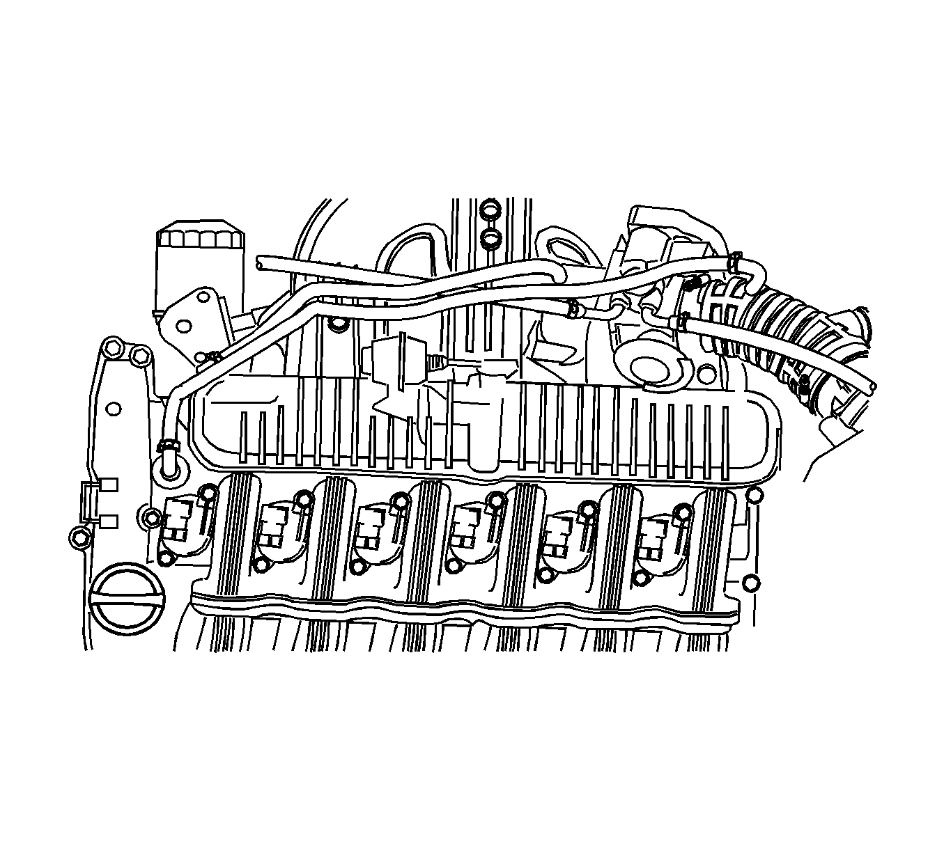
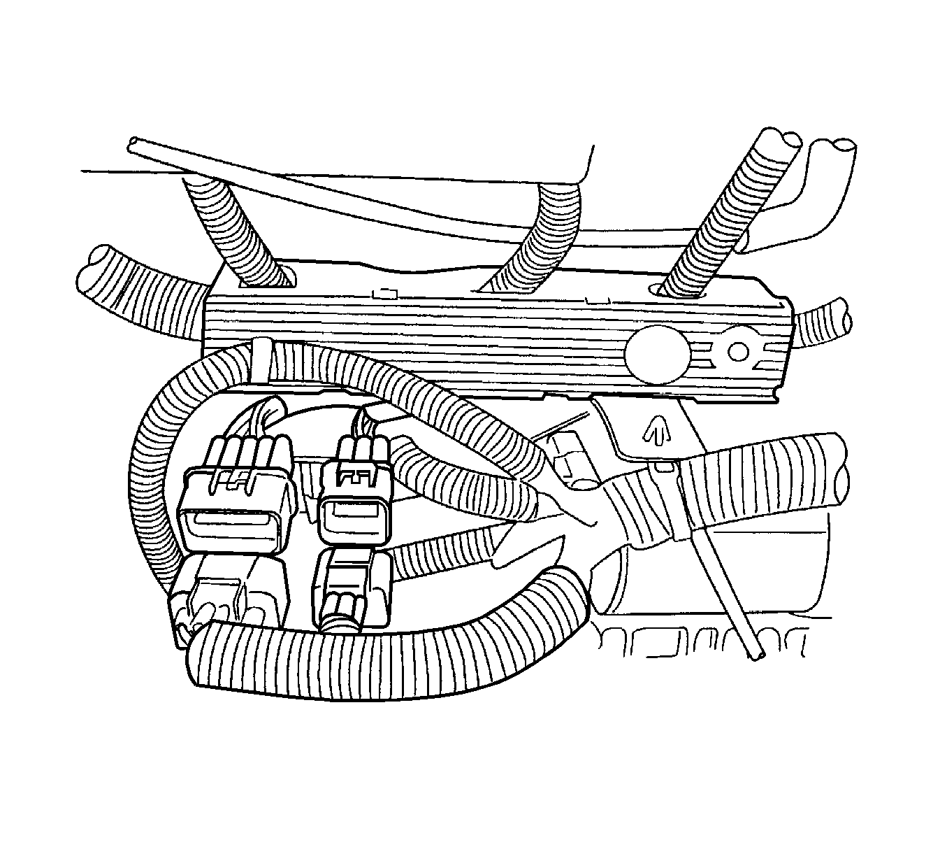
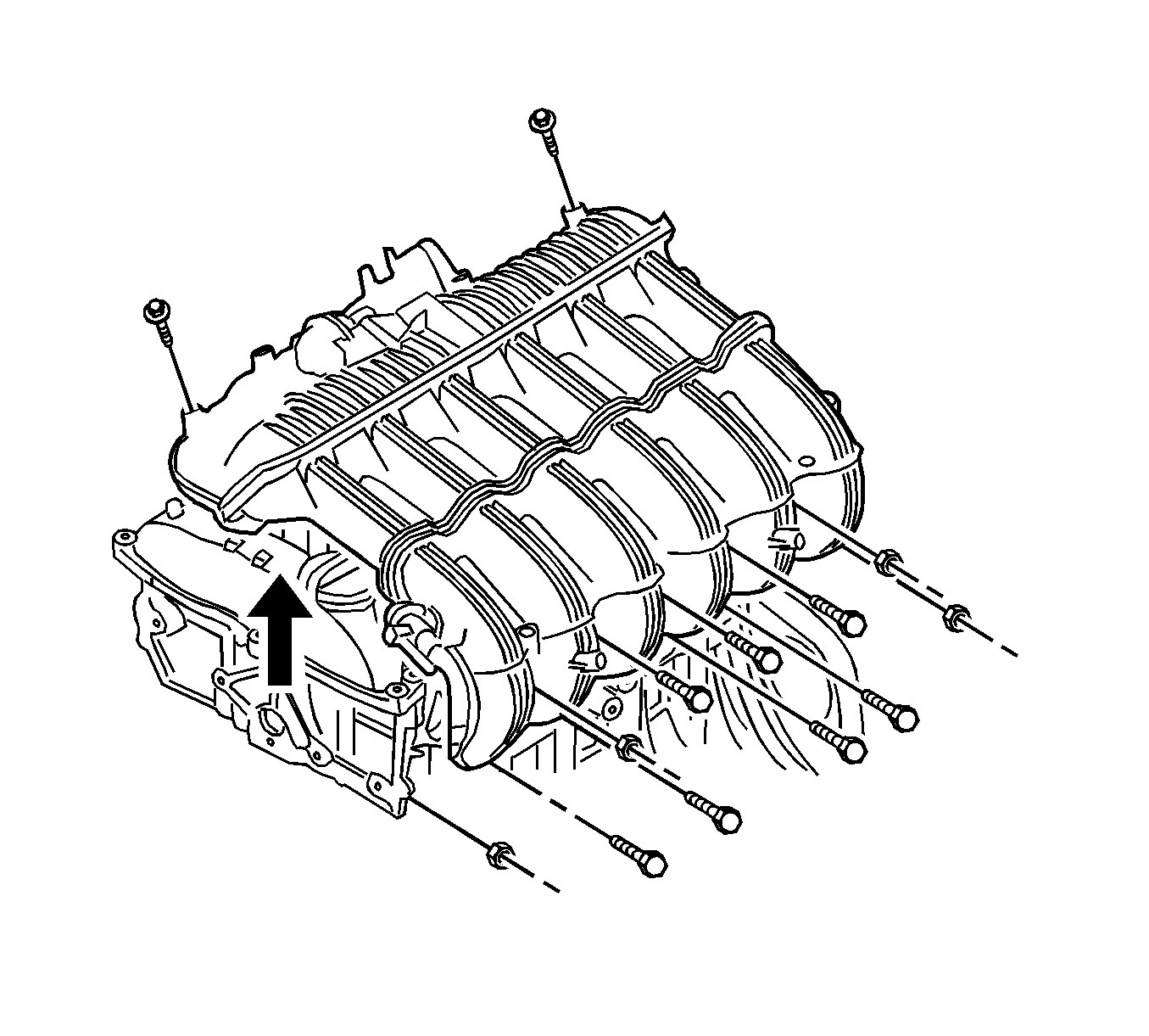
Note: Remove the fuel rail after removing the intake manifold.
Installation Procedure
- Discard used intake manifold gaskets and install new ones.
- Install the intake manifold.
- Install the intake manifold retaining nuts and bolts.
- Install the intake manifold support bracket and tighten to 12 N·m (106 lb in).
- Install the wiring harness to the supporting bracket on the cylinder block.
- Install the ECT sensor.
- Install the EGR pipe to the intake manifold.
- Install the intake EGR pipe retaining bolts on the intake manifold and tighten the bolts to 10 N·m (89 lb in).
- Install the vacuum hose to the brake booster.
- Connect the ignition coil connector.
- Install the IAT sensor and tighten to 25 N·m (18 lb in).
- Connect the CMP sensor connector.
- Connect the EGR solenoid connector.
- Connect the CKP sensor connector.
- Connect the MAP sensor connector.
- Connect the HO2S connector.
- Connect the charcoal canister purge solenoid connector and hose.
- Install the throttle body assembly. Refer to Throttle Body Assembly Replacement and tighten the throttle body assembly retaining bolts to 13 N·m (115 lb in).
- Install the PCV vacuum hose.
- Install the breather hose.
- Install the fuel pressure regulator. Refer to Fuel Pressure Regulator Replacement Tighten the fuel pressure regulator retaining bolts to 12 N·m (106 lb in).
- Install the VIS vacuum tank. Refer to Intake Manifold Tuning Valve Vacuum Reservoir Replacement Tighten the VIS vacuum tank retaining bolts to 8 N·m (71 lb in).
- Install the air filter snorkel and tighten the retaining bolts to 6 N·m (53 lb in).
- Install the engine beautification cover and tighten the retaining bolts to 10 N·m (89 lb in).
- Install the fuel pump fuse.
- Connect the negative battery cable.
- Refill the engine cooling system. Refer to Cooling System Draining and Filling.
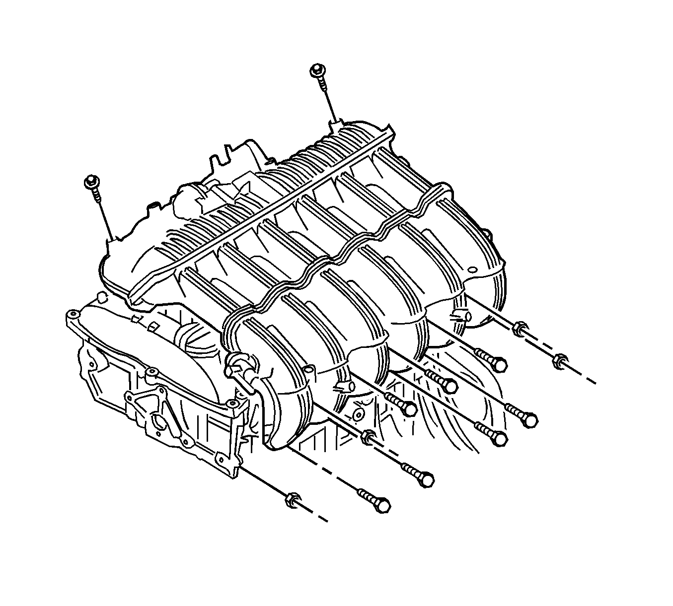
Note: Install the intake manifold after installing the fuel rail.
Caution: Refer to Fastener Caution in the Preface section.
| • | Tighten the 7 intake manifold retaining bolts to 12 N·m (106 lb in). |
| • | Tighten the 4 intake manifold retaining nuts to 12 N·m (106 lb in). |

