For 1990-2009 cars only
Removal Procedure
- Remove the center trim bezel from the instrument panel. Refer to Instrument Panel Accessory Bezel Replacement in Instrument Panel, Gages and Console.
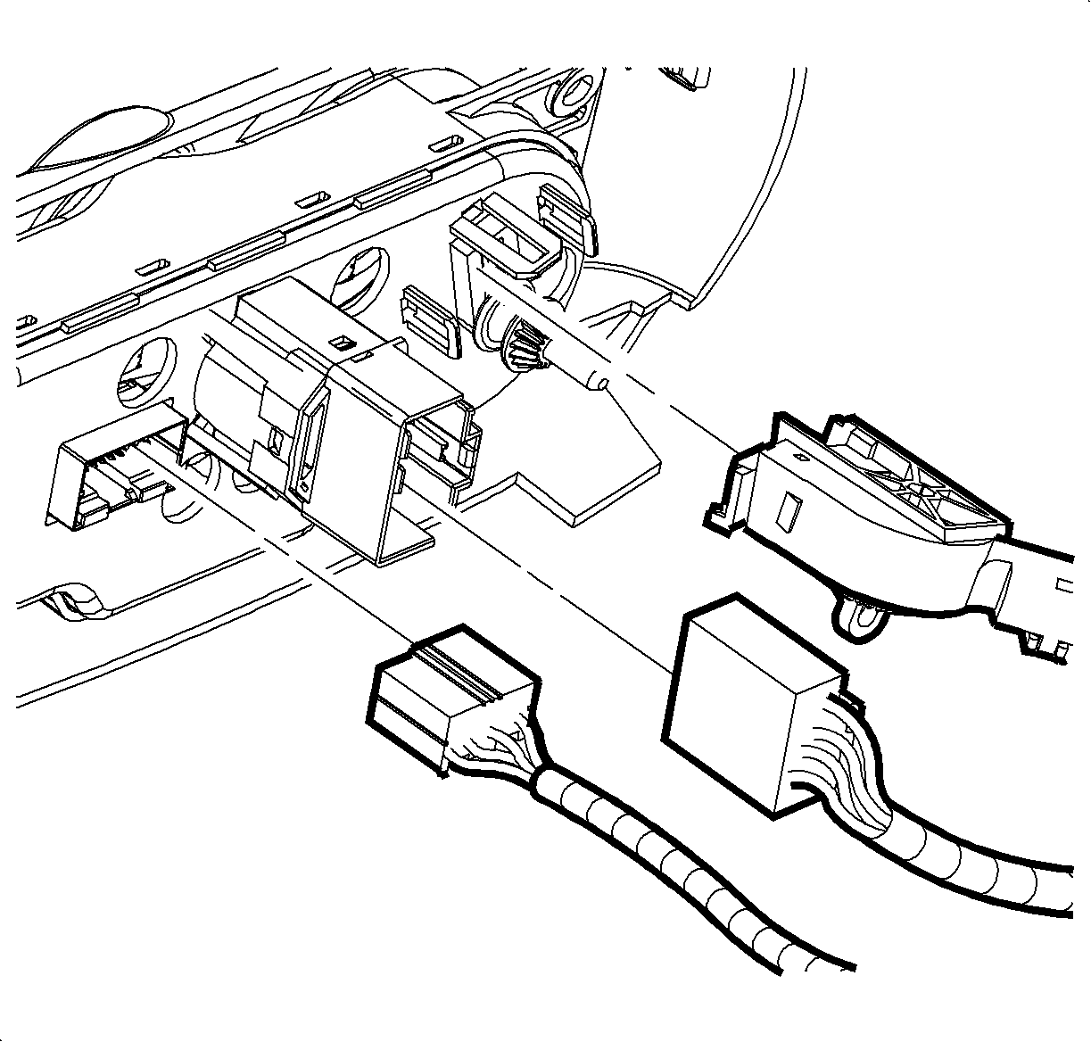
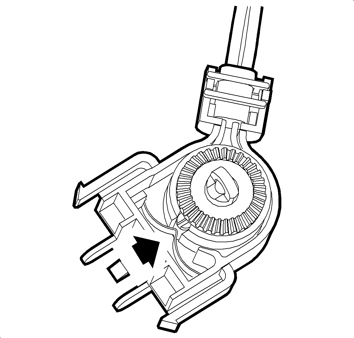
- Disconnect the temperature cable from the HVAC control module.
- Disconnect the blower switch from the HVAC control module.
- Disconnect the electrical connector from the HVAC control module.
- Disconnect the remaining electrical connectors from the center trim bezel.
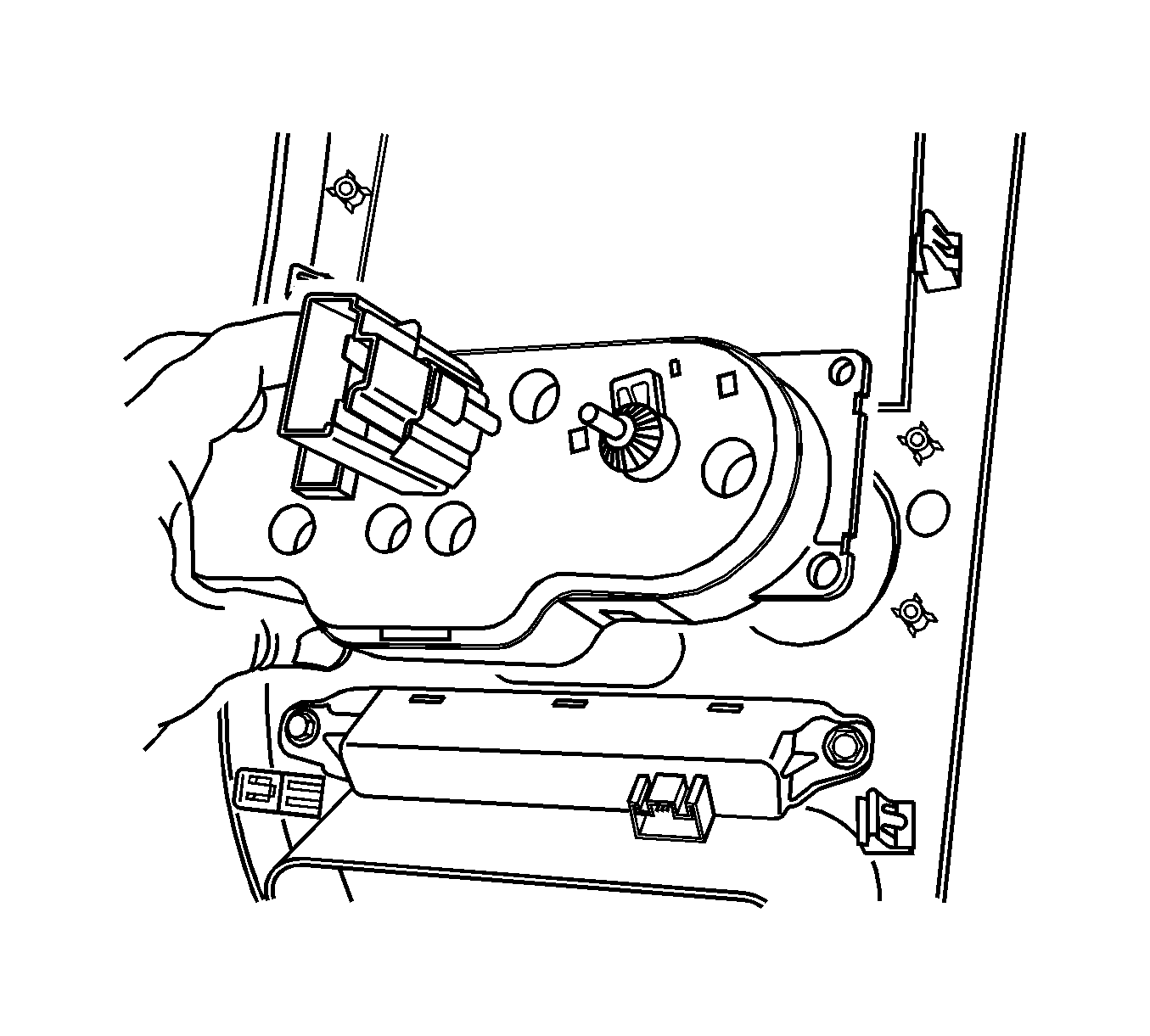
- Remove the HVAC control module screws from the center trim bezel.
- Remove the HVAC control module from the center trim bezel.


Installation Procedure
- Install the HVAC control module to the center trim bezel.
- Install the HVAC control module screws to the center trim bezel.
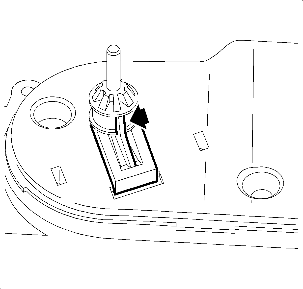
- Center the temperature cable knob by inserting the assembly alignment tab into the centering slot of the temperature knob shaft.
- Center the HVAC module temperature door by aligning the cable lug of the temperature control cable with the center point of the detent spring. The detent spring force should hold the temperature door in the desired position.
- Connect the temperature cable to the HVAC control module.
- Connect the blower switch to the HVAC control module.
- Connect the electrical connector to the HVAC control module.
- Connect the remaining electrical connectors to the center trim bezel.
- Install the center trim bezel to the instrument panel. Refer to Instrument Panel Accessory Bezel Replacement in Instrument Panel, Gages and Console.
- Calibrate the mode doors by simultaneously pushing the A/C and RECIRC buttons on the HVAC control module 3 times each, within 2 seconds of initial push.
- Cycle the ignition and verify proper operation.
- Refer to Control Module References for programming and setup information.

Notice: Refer to Fastener Notice in the Preface section.
Tighten
Tighten the screws to 2.5 N·m (22 lb in).


Important: Any time a mode actuator or the HVAC control module is replaced, the HVAC control module must be calibrated to ensure proper air distribution.
| • | The A/C and RECIRC button LED's will flash while this calibration is taking place. |
| • | The calibration will take anywhere between 10-30 seconds depending on battery voltage. |
| • | The LED's will quit flashing when the calibration is complete. |
