For 1990-2009 cars only
Tools Required
| • | J 43828 Ball Joint Remover |
| • | J 44015 Steering Linkage Installer |
| • | SA91100C Tie Rod Separator |
| • | SA9140E Torque Angle Gage |
Removal Procedure
- Raise and support the vehicle. Refer to Lifting and Jacking the Vehicle in General Information.
- Remove the tire and wheel. Refer to Tire and Wheel Removal and Installation in Tires and Wheels.
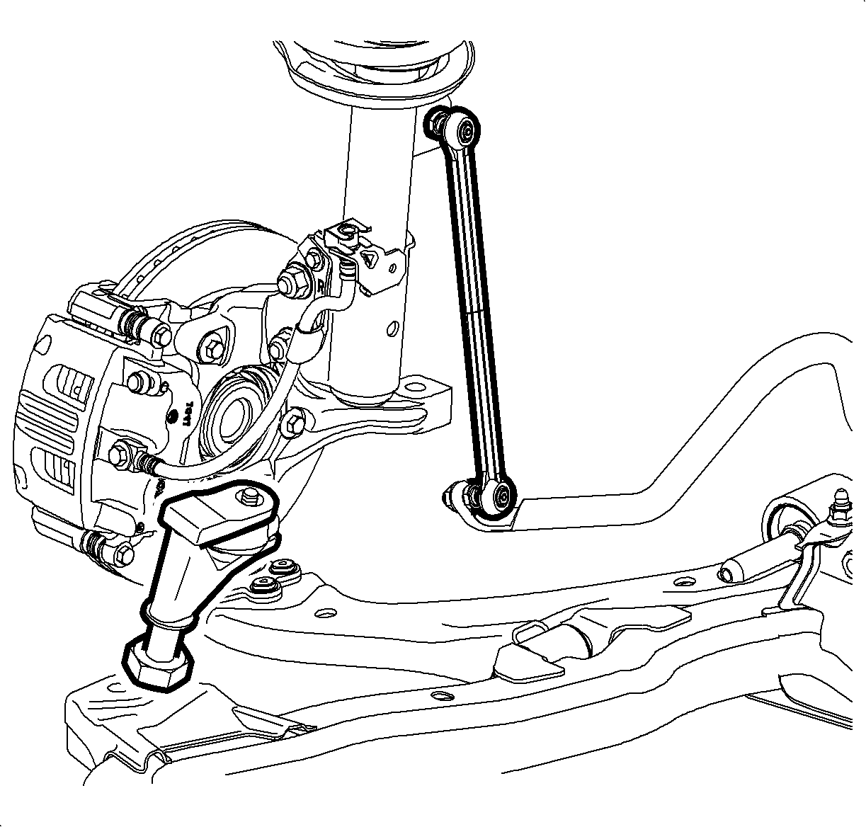
- Disconnect the stabilizer link from the strut assembly.
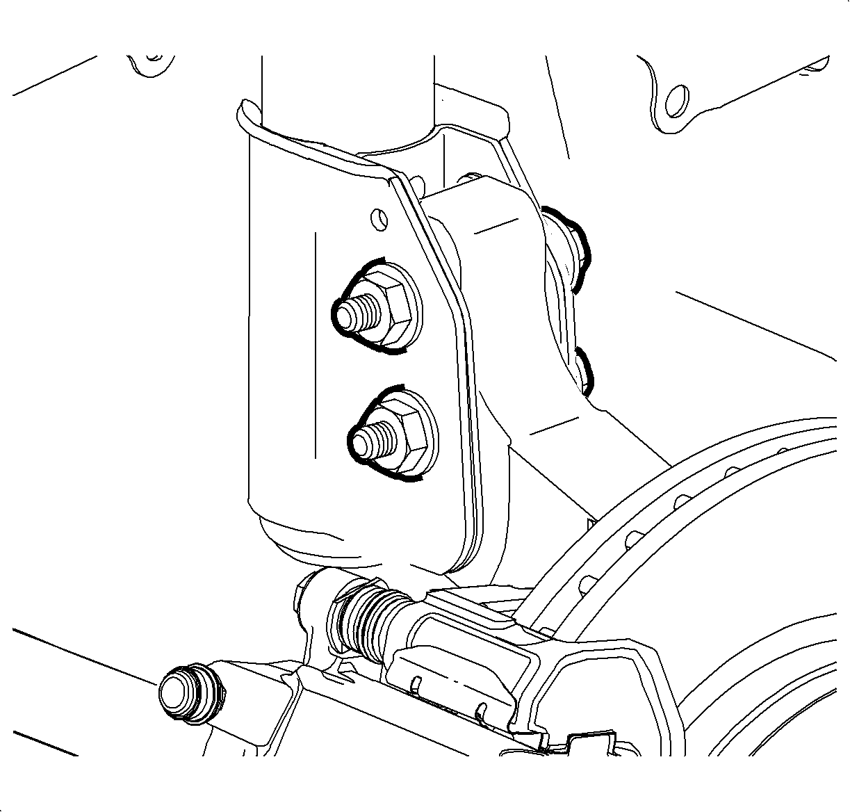
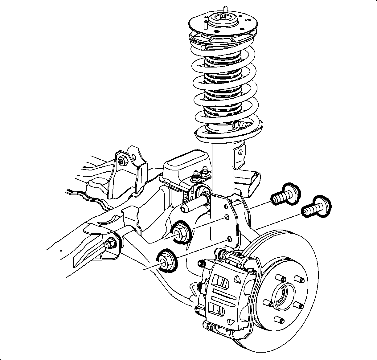
- Loosen the steering knuckle to strut bolts and nuts.
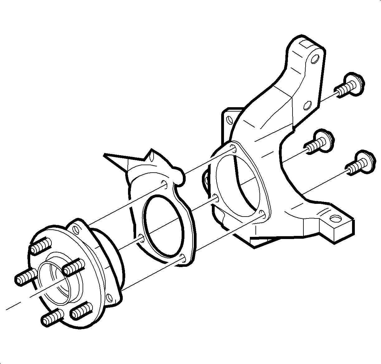
- Remove the wheel bearing/hub assembly. Refer to Front Wheel Bearing and Hub Replacement .
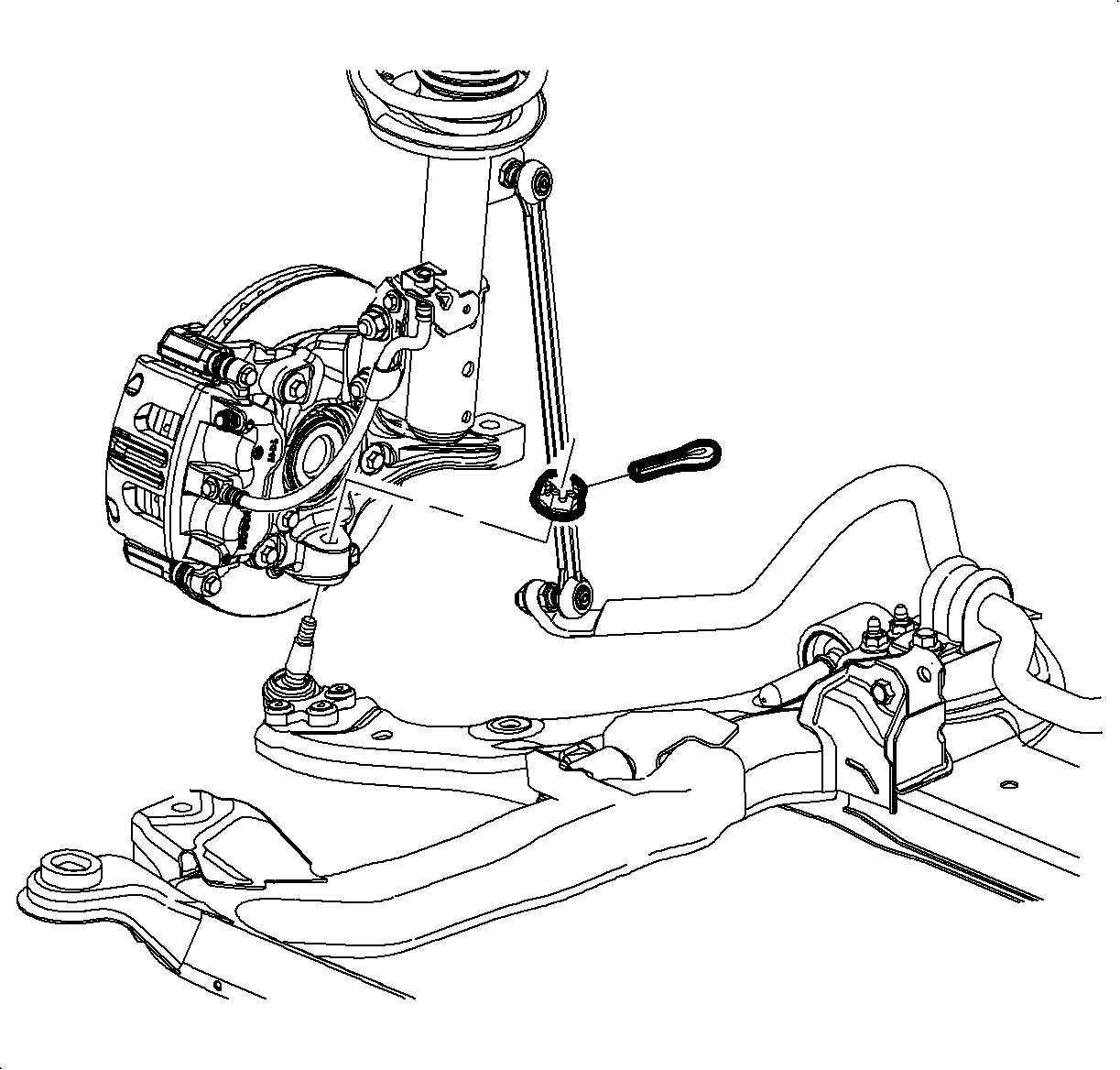
- Remove and discard the lower ball joint cotter pin.
- Loosen the ball stud nut, until level with the top of the ball stud.
- Using the J 43828 , separate the lower control arm from the steering knuckle.
- Remove the lower control arm and nut from the steering knuckle.
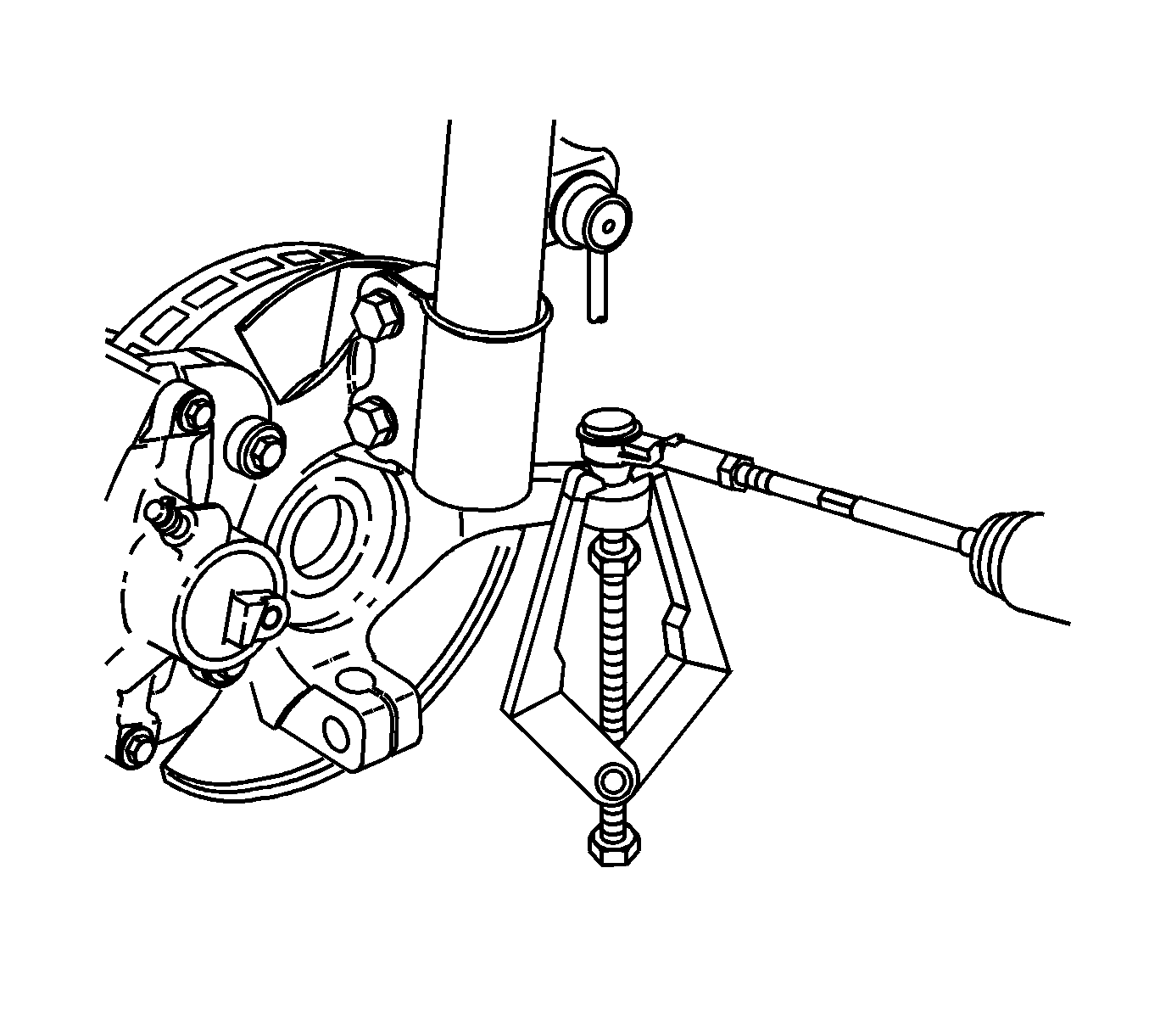
- Remove the outer tie rod end to knuckle nut.
- Using the SA91100C , separate the outer tie rod from the steering knuckle.
- Remove the steering knuckle to strut bolts and nuts. Discard the bolts and nuts.
- Remove the steering knuckle from the vehicle.
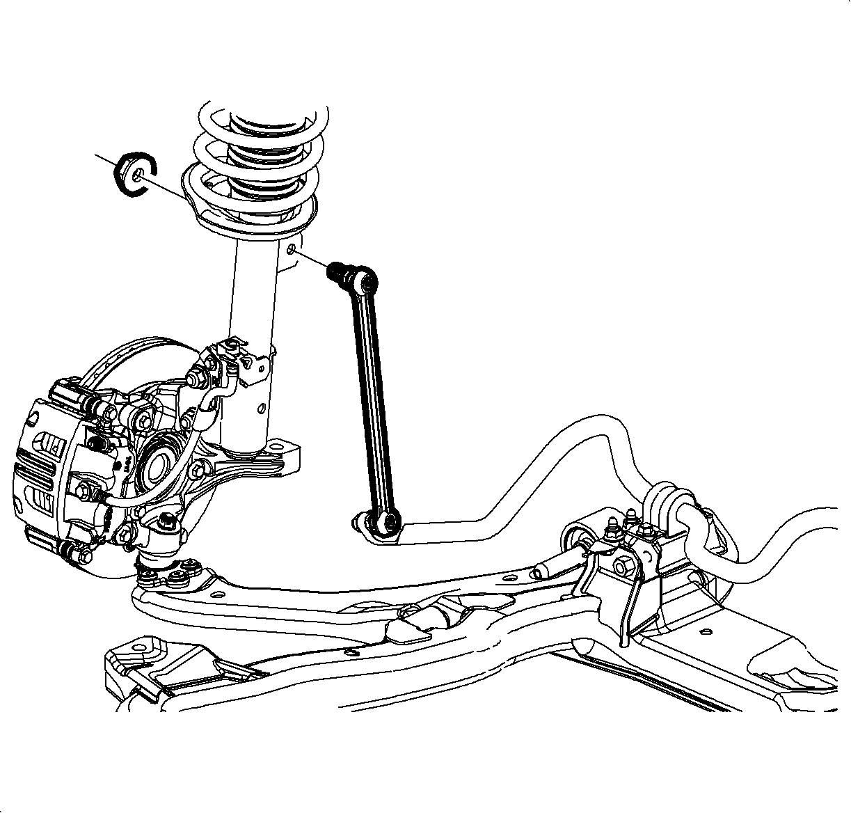
Important: Do not allow the stabilizer link ball stud to rotate while removing the link nut.
Installation Procedure
- Install the steering knuckle to strut assembly.
- Loosely install the strut to steering knuckle bolts and nuts.
- Install the control arm ball stud into the steering knuckle.
- Using the SA9140E , install the ball stud nut.
- If the bottom of the ball stud has a cup and is silver, tighten the nut to 60 N·m (44 lb ft).
- If the bottom of the ball stud is flat and black, tighten the nut to 40 N·m (30 lb ft).
- Tighten the strut to steering knuckle bolts and nuts.
- Tighten the castle nut enough to allow for cotter pin installation.
- Install the cotter pin.
- Install the wheel bearing/hub assembly. Refer to Front Wheel Bearing and Hub Replacement .
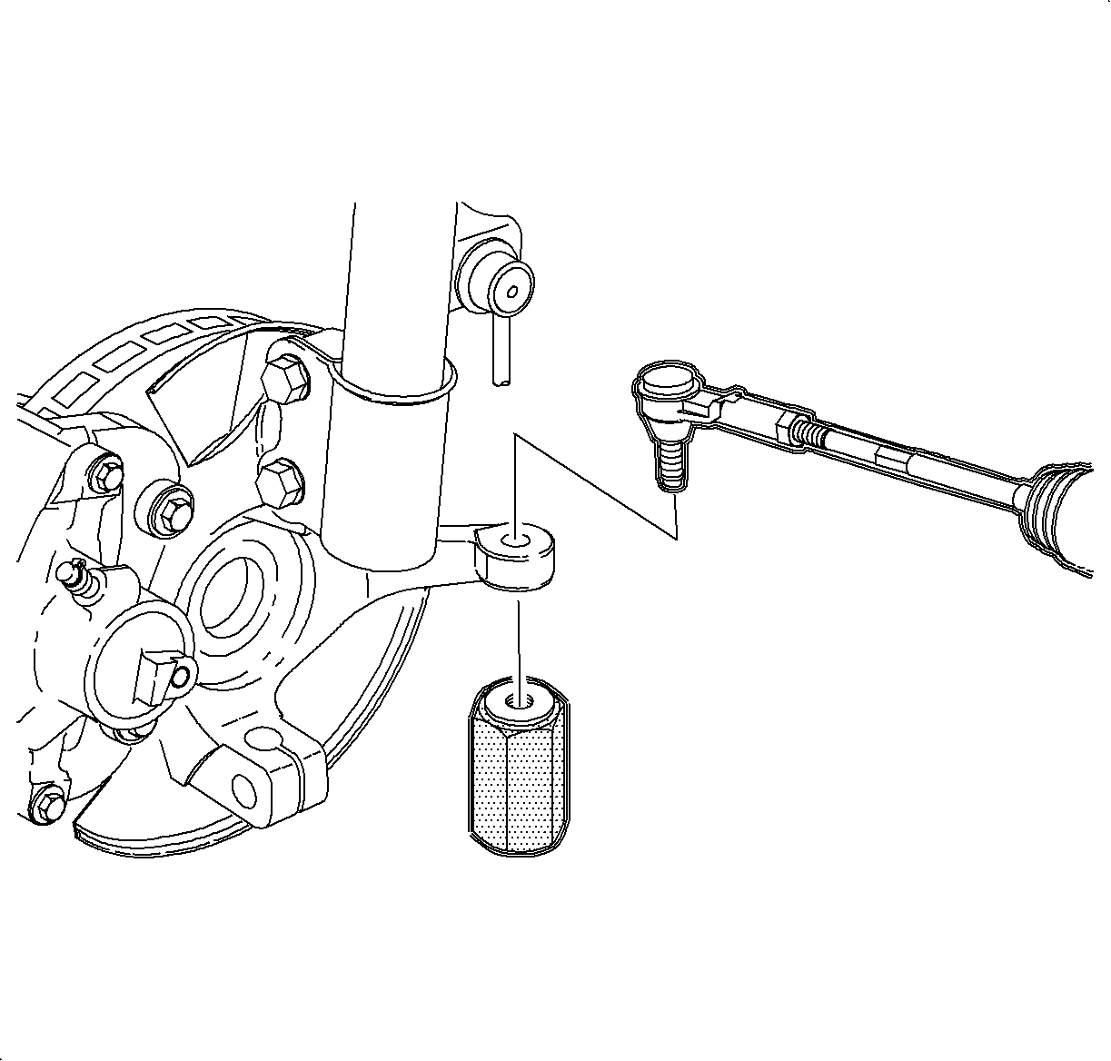
- Connect the outer tie rod end to the steering knuckle.
- Use the J 44015 to seat the ball stud taper.
- Remove the J 44015 .
- Install a new tie rod retention nut.
- Connect the stabilizer link to the strut assembly.
- Install the tire and wheel. Refer to Tire and Wheel Removal and Installation in Tires and Wheels.
- Lower the vehicle.
- Perform a wheel alignment. Refer to Wheel Alignment Measurement in Wheel Alignment.


Notice: Refer to Fastener Notice in the Preface section.
Notice: Refer to Lower Control Arm Ball Stud Identification Notice in the Preface section.
Tighten
Tighten
Tighten the bolts and nuts to 180 N·m (133 lb ft).
Important: Do not loosen the castle nut for cotter pin installation.
Important: The cotter pin must not contact the wheel speed sensor or drive axle.

Tighten
Tighten to 40 N·m (30 lb ft).
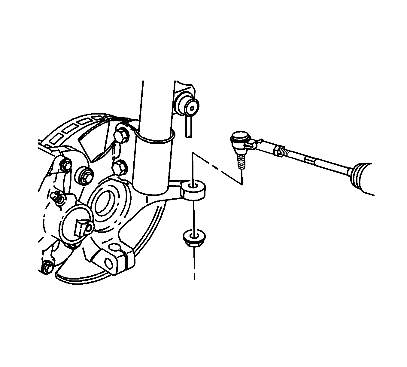
Tighten
Tighten the nut to 50 N·m (37 lb ft).

Important: Do not allow the stabilizer link ball stud to rotate while installing the link nut.
Tighten
Tighten the nut to 65 N·m (48 lb ft).
