C100 Wiring Harness Side to Transmission Side
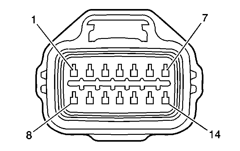
|
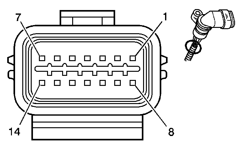
|
Connector Part Information
| Connector Part Information
|
Pin | Wire Color | Circuit No. | Function | Pin | Wire Color | Circuit No. | Function |
|---|---|---|---|---|---|---|---|
1 | OG/BK | 586 | Transmission Fluid Temperature Sensor Low Reference | 1 | OG | 586 | Transmission Fluid Temperature Sensor Low Reference |
2 | GY | 5508 | Shift Pressure Control Solenoid Valve Low Control | 2 | BU | 5508 | Shift Pressure Control Solenoid Valve Low Control |
3 | D-BU | 5509 | TCC Pressure Control Solenoid Valve Low Control | 3 | BN | 5509 | TCC Pressure Control Solenoid Valve Low Control |
4 | PU/WH | 5510 | Line Pressure Control Solenoid Valve Low Control | 4 | GY | 5510 | Line Pressure Control Solenoid Valve Low Control |
5 | -- | -- | Not Used | 5 | -- | -- | Not Used |
6 | YE/BK | 2879 | Shift Solenoid Valve 4 Control | 6 | PU | 2879 | Shift Solenoid Valve 4 Control |
7 | YE/BK | 1223 | Shift Solenoid Valve 2 Control | 7 | BK | 1223 | Shift Solenoid Valve 2 Control |
8 | TN/WH | 585 | Transmission Fluid Temperature Sensor Signal | 8 | OG | 585 | Transmission Fluid Temperature Sensor Signal |
9 | WH | 2880 | Shift Pressure Control Solenoid Valve Low Control | 9 | RD | 2880 | Shift Pressure Control Solenoid Valve High Control |
10 | D-GN | 5511 | TCC Pressure Control Solenoid Valve High Control | 10 | L-GN | 5511 | TCC Pressure Control Solenoid Valve High Control |
11 | WH | 1994 | Line Pressure Control Solenoid Valve High Control | 11 | GN | 1994 | Line Pressure Control Solenoid Valve High Control |
12 | OG/WH | 2527 | Shift Solenoid Valve 5 Control | 12 | L-BU | 2527 | Shift Solenoid Valve 5 High Control |
13 | PU | 898 | Shift Solenoid Valve 3 Control | 13 | YE | 898 | Shift Solenoid Valve 3 High Control |
14 | L-GN | 1222 | Shift Solenoid Valve 1 Control | 14 | WH | 1222 | Shift Solenoid Valve 1 High Control |
C102 - Body Harness to the Engine Harness
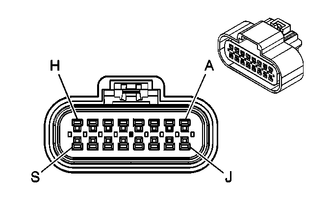
|
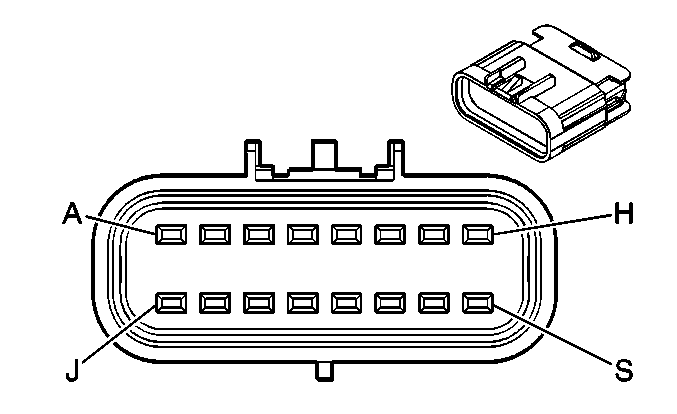
|
Connector Part Information
| Connector Part Information
|
Pin | Wire Color | Circuit No. | Function | Pin | Wire Color | Circuit No. | Function |
|---|---|---|---|---|---|---|---|
A | BN | 1271 | Low Reference | A | BN | 1271 | Low Reference |
B | WH/BK | 1164 | 5-Volt Reference | B | WH/BK | 1164 | 5-Volt Reference |
C | L-BU | 1162 | APP Sensor 2 Signal | C | L-BU | 1162 | APP Sensor 2 Signal |
D | TN | 1274 | 5-Volt Reference | D | TN | 1274 | 5-Volt Reference |
E | PU | 1272 | Low Reference | E | PU | 1272 | Low Reference |
F | D-BU | 1161 | APP Sensor 1 Signal | F | D-BU | 1161 | APP Sensor 1 Signal |
G | TN | 2501 | High Speed GMLAN Serial Data Bus (-) | G | TN | 2501 | High Speed GMLAN Serial Data Bus (-) |
H | TN/BK | 2500 | High Speed GMLAN Serial Data Bus (+) | H | TN/BK | 2500 | High Speed GMLAN Serial Data Bus (+) |
J | GY | 2709 | 5-Volt Reference | J | GY | 2709 | 5-Volt Reference |
K | D-GN | 890 | Fuel Tank Pressure Sensor Signal | K | D-GN | 890 | Fuel Tank Pressure Sensor Signal |
L | GY | 1884 | Cruise Control Set/Coast and Resume/Accelerate Switch Signal | L | GY | 1884 | Cruise Control Set/Coast and Resume/Accelerate Switch Signal |
M-N | -- | -- | Not Used | M-N | -- | -- | Not Used |
P | PU | 1589 | Fuel Level Sensor Signal | P | PU | 1589 | Fuel Level Sensor Signal |
R | -- | -- | Not Used | R | -- | -- | Not Used |
S | RD/WH | 1440 | Battery Positive Voltage | S | RD/WH | 1440 | Battery Positive Voltage |
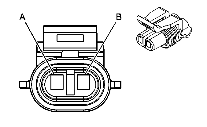
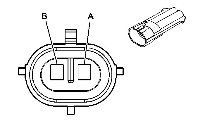
C104 - LF WSS Harness to the Body Harness (JM4)
|
|
Connector Part Information
| Connector Part Information
|
Pin | Wire Color | Circuit No. | Function | Pin | Wire Color | Circuit No. | Function |
|---|---|---|---|---|---|---|---|
A | L-BU | 830 | LF Wheel Speed Sensor Signal | A | L-BU | 830 | LF Wheel Speed Sensor Signal |
B | YE | 873 | LF Wheel Speed Sensor Low Reference | B | YE | 873 | LF Wheel Speed Sensor Low Reference |
C105 - RF WSS Harness to the Body Harness (JM4)

|

|
Connector Part Information
| Connector Part Information
|
Pin | Wire Color | Circuit No. | Function | Pin | Wire Color | Circuit No. | Function |
|---|---|---|---|---|---|---|---|
A | D-GN | 872 | RF Wheel Speed Sensor Signal | A | D-GN | 872 | RF Wheel Speed Sensor Signal |
B | TN | 833 | RF Wheel Speed Sensor Low Reference | B | TN | 833 | RF Wheel Speed Sensor Low Reference |
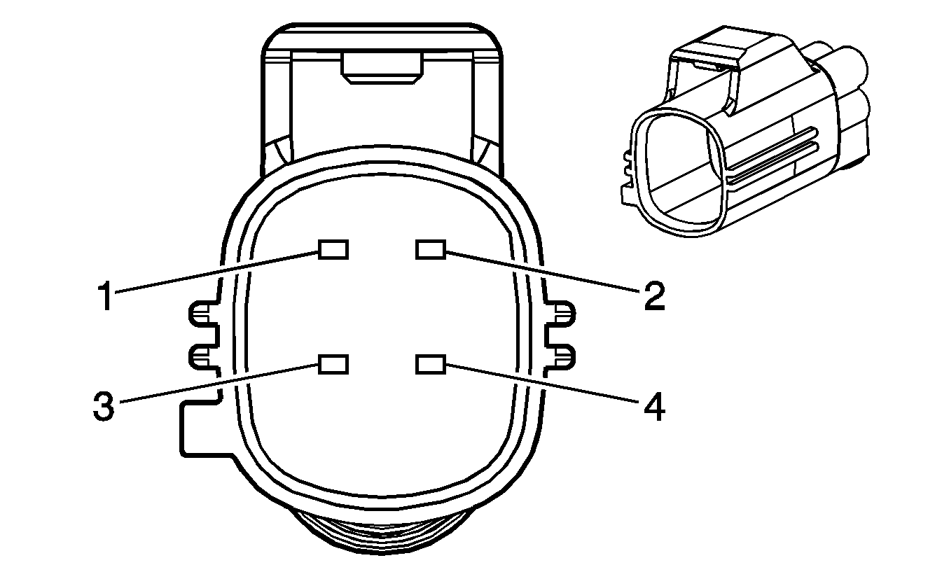
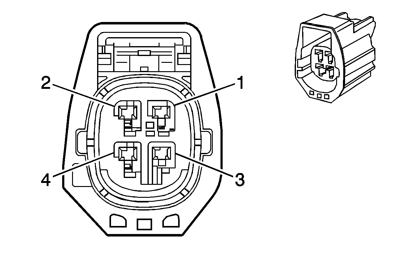
C106 - Body Harness to the Forward Lamp Harness
|
|
Connector Part Information
| Connector Part Information
|
Pin | Wire Color | Circuit No. | Function | Pin | Wire Color | Circuit No. | Function |
|---|---|---|---|---|---|---|---|
1 | L-GN/BK | 735 | Ambient Air Temperature Sensor Signal (DH3/DF5) | 1 | L-GN/BK | 735 | Ambient Air Temperature Sensor Signal (DH3/DF5) |
2 | GY | 720 | Low Reference (DH3/DF5) | 2 | GY | 720 | Low Reference (DH3/DF5) |
3 | TN/OG | 5045 | Front End Sensor Signal (ASF) | 3 | TN/OG | 5045 | Front End Sensor Signal (ASF) |
4 | YE | 1834 | Front End Sensor Voltage (ASF) | 4 | YE | 1834 | Front End Sensor Voltage (ASF) |
C150 - Engine Harness to the Fuel Rail Harness

|
Connector Part Information
| Connector Part Information
|
Pin | Wire Color | Circuit No. | Function | Pin | Wire Color | Circuit No. | Function |
|---|---|---|---|---|---|---|---|
A | PK/BK | 5292 | Ignition 1 Voltage | A | PK | 5292 | Ignition 1 Voltage |
B | YE | 410 | ECT Sensor Signal | B | YE | 410 | ECT Sensor Signal |
C | TN | 1744 | Fuel Injector 1 Control | C | BK | 1744 | Fuel Injector 1 Control |
D | L-GN/BK | 1745 | Fuel Injector 2 Control | D | L-GN/BK | 1745 | Fuel Injector 2 Control |
E | PK/BK | 1746 | Fuel Injector 3 Control | E | PK/BK | 1746 | Fuel Injector 3 Control |
F | L-BU/BK | 844 | Fuel Injector 4 Control | F | L-BU/BK | 844 | Fuel Injector 4 Control |
G | TN/WH | 845 | Fuel Injector 5 Control | G | BK/WH | 845 | Fuel Injector 5 Control |
H | YE/BK | 846 | Fuel Injector 6 Control | H | YE/BK | 846 | Fuel Injector 6 Control |
J | -- | -- | Not Used | J | -- | -- | Not Used |
K | GY | 2704 | 5-Volt Reference | K | GY | 2704 | 5-Volt Reference |
L | OG/BK | 469 | Low Reference | L | OG/BK | 469 | Low Reference |
M | L-GN | 432 | MAP Sensor Signal | M | L-GN | 432 | MAP Sensor Signal |
N | OG | 631 | 12-Volt Reference | N | RD/WH | 631 | 12-Volt Reference |
P | PK/BK | 632 | Low Reference | P | BK | 632 | Low Reference |
R | BN/WH | 633 | CMP Sensor Signal | R | BN/WH | 633 | CMP Sensor Signal |
S | -- | -- | Not Used | S | -- | -- | Not Used |
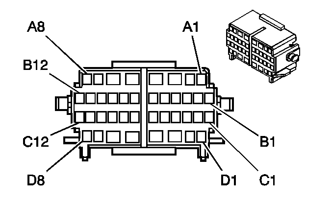
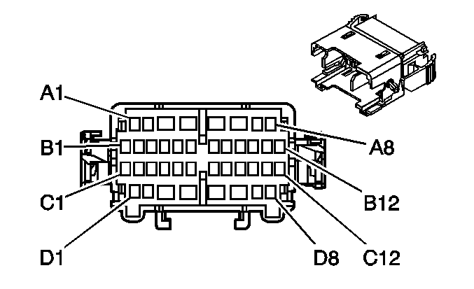
C200 - I/P Harness to the Body Harness
|
|
Connector Part Information
| Connector Part Information
|
Pin | Wire Color | Circuit No. | Function | Pin | Wire Color | Circuit No. | Function |
|---|---|---|---|---|---|---|---|
A1 | L-GN | 89 | Driver Mirror Motor Down Control | A1 | L-GN | 89 | Driver Mirror Motor Down Control |
A2 | WH | 81 | Driver Mirror Motor Right Control | A2 | WH | 81 | Driver Mirror Motor Right Control |
A3 | YE | 343 | Accessory Voltage | A3 | YE | 343 | Accessory Voltage |
A4 | -- | -- | Not Used | A4 | -- | -- | Not Used |
A5 | RD/WH | 40 | Battery Positive Voltage | A5 | RD/WH | 40 | Battery Positive Voltage |
A6 | D-GN | 95 | Windshield Wiper Motor Low Speed Control | A6 | D-GN | 95 | Windshield Wiper Motor Low Speed Control |
A7 | PK/BK | 1503 | Passenger Heated Seat High/Low Signal (KA1) | A7 | PK/BK | 1503 | Passenger Heated Seat High/Low Signal (KA1) |
A8 | BN | 1271 | Accelerator Pedal Position Low Reference | A8 | BN | 1271 | Accelerator Pedal Position Low Reference |
B1 | PU/WH | 889 | Passenger Mirror Motor Down Control | B1 | PU/WH | 889 | Passenger Mirror Motor Down Control |
B2 | YE | 1496 | Mirror Motor Left/Up Control | B2 | YE | 1496 | Mirror Motor Left/Up Control |
B3 | OG/WH | 881 | Passenger Mirror Motor Right Control | B3 | OG/WH | 881 | Passenger Mirror Motor Right Control |
B4 | L-BU | 1162 | APP Sensor 2 Signal | B4 | L-BU | 1162 | APP Sensor 2 Signal |
B5 | PU | 1272 | Accelerator Pedal Position Low Reference | B5 | PU | 1272 | Accelerator Pedal Position Low Reference |
B6 | YE | 1834 | Front End Sensor Voltage | B6 | YE | 1834 | Front End Sensor Voltage |
B7 | WH/BK | 1164 | Accelerator Pedal Position 5-Volt Reference - A | B7 | WH/BK | 1164 | Accelerator Pedal Position 5-Volt Reference - A |
B8 | GY | 1884 | Cruise Control Set/Coast/Resume/Accel Switch Signal (K34, UK3) | B8 | GY | 1884 | Cruise Control Set/Coast/Resume/Accel Switch Signal (K34, UK3) |
B9 | PK | 1501 | Driver Heated Seat High/Low Signal (KA1) | B9 | PK | 1501 | Driver Heated Seat High/Low Signal (KA1) |
B10 | RD/WH | 1840 | Battery Positive Voltage | B10 | RD/WH | 1840 | Battery Positive Voltage |
B11 | TN | 1274 | Accelerator Pedal Position 5-Volt Reference - B | B11 | TN | 1274 | Accelerator Pedal Position 5-Volt Reference - B |
B12 | D-BU | 1161 | APP Sensor 1 Signal | B12 | D-BU | 1161 | APP Sensor 1 Signal |
C1-C2 | -- | -- | Not Used | C1-C2 | -- | -- | Not Used |
C3 | RD/WH | 440 | Battery Positive Voltage | C3 | RD/WH | 440 | Battery Positive Voltage |
C4-C5 | -- | -- | Not Used | C4-C5 | -- | -- | Not Used |
C6 | PU | 420 | Brake/Cruise Release Switch Signal | C6 | PU | 420 | Brake/Cruise Release Switch Signal |
C7 | TN/OG | 5045 | Front End Sensor Signal | C7 | TN/OG | 5045 | Front End Sensor Signal |
C8 | BN/WH | 419 | MIL Control | C8 | BN/WH | 419 | MIL Control |
C9 | L-BU | 20 | Stop Lamp Switch Signal | C9 | L-BU | 20 | Stop Lamp Switch Signal |
C10-C11 | -- | -- | Not Used | C10-C11 | -- | -- | Not Used |
C12 | RD/WH | 540 | Battery Positive Voltage | C12 | RD/WH | 540 | Battery Positive Voltage |
D1 | TN | 2501 | High Speed GMLAN Serial Data Bus (-) | D1 | TN | 2501 | High Speed GMLAN Serial Data Bus (-) |
D2 | TN/BK | 2500 | High Speed GMLAN Serial Data Bus (+) | D2 | TN/BK | 2500 | High Speed GMLAN Serial Data Bus (+) |
D3 | PU | 92 | Windshield Wiper Motor High Speed Control | D3 | PU | 92 | Windshield Wiper Motor High Speed Control |
D4 | L-BU | 97 | Windshield Wiper Switch Mist/Off/Low Signal | D4 | L-BU | 97 | Windshield Wiper Switch Mist/Off/Low Signal |
D5 | RD/WH | 40 | Battery Positive Voltage | D5 | RD/WH | 40 | Battery Positive Voltage |
D6 | RD/WH | 1140 | Battery Positive Voltage | D6 | RD/WH | 1140 | Battery Positive Voltage |
D7 | OG/BK | 6848 | Front Wiper Relay Control | D7 | OG/BK | 6848 | Front Wiper Relay Control |
D8 | -- | -- | Not Used | D8 | -- | -- | Not Used |
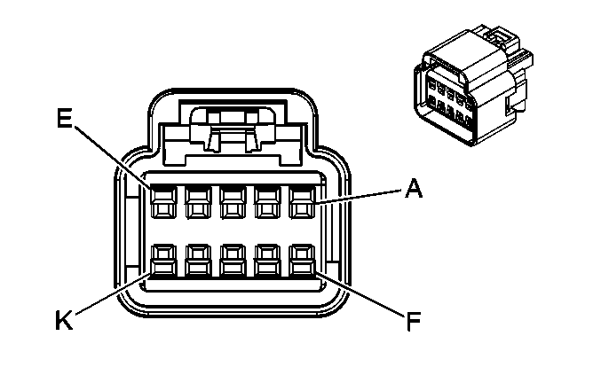
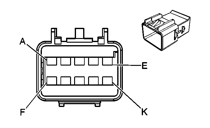
C202 - I/P Harness to the HVAC Harness
|
|
Connector Part Information
| Connector Part Information
|
Pin | Wire Color | Circuit No. | Function | Pin | Wire Color | Circuit No. | Function |
|---|---|---|---|---|---|---|---|
A | PU | 361 | Mode Door Control A | A | PU | 361 | Mode Door Control A |
B | PU/WH | 3361 | Mode Door Control B | B | PU/WH | 3361 | Mode Door Control B |
C | YE/BK | 713 | Mode Door Position Signal | C | YE/BK | 713 | Mode Door Position Signal |
D | GY | 705 | 5-Volt Reference | D | GY | 705 | 5-Volt Reference |
E | TN | 407 | Low Reference | E | TN | 407 | Low Reference |
F | L-GN/BK | 366 | Air Temperature Door Control A | F | L-GN/BK | 366 | Air Temperature Door Control A |
G | L-GN/WH | 3366 | Air Temperature Door Control B | G | L-GN/WH | 3366 | Air Temperature Door Control B |
H | YE/BK | 1814 | Lower Mode Door Position Signal | H | YE/BK | 1814 | Lower Mode Door Position Signal |
J | GY | 731 | Evaporator Temperature Sensor Signal | J | GY | 731 | Evaporator Temperature Sensor Signal |
K | PU | 719 | Low Reference | K | PU | 719 | Low Reference |
C204 - I/P Harness to the Body Harness
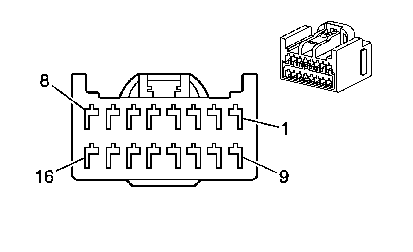
|
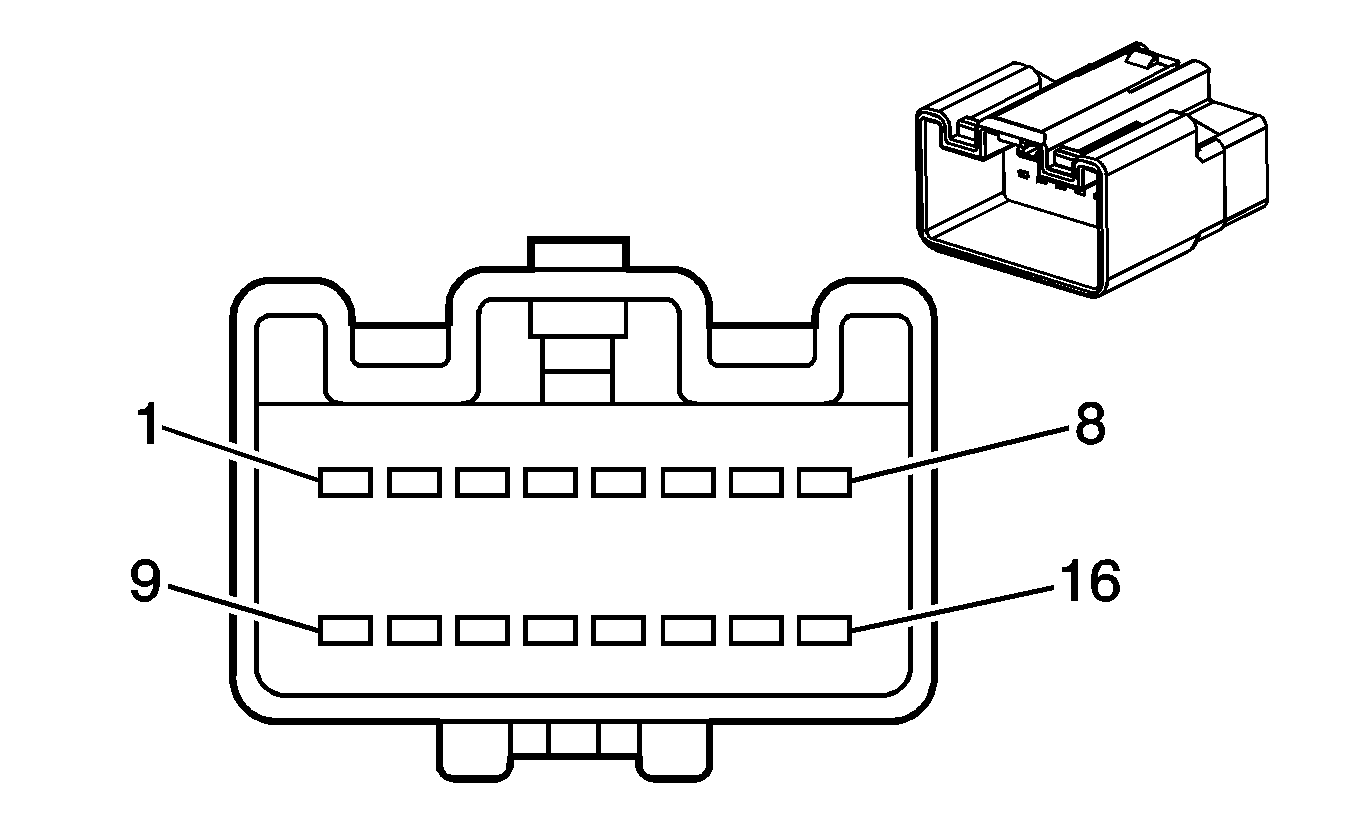
|
Connector Part Information
| Connector Part Information
|
Pin | Wire Color | Circuit No. | Function | Pin | Wire Color | Circuit No. | Function |
|---|---|---|---|---|---|---|---|
1 | TN | 201 | Left Front Speaker Output (+) | 1 | TN | 201 | Left Front Speaker Output (+) (U1C) |
511 | Left Front Speaker Output (+) (U65) | ||||||
2 | GY | 118 | Left Front Speaker Output (-) | 2 | GY | 118 | Left Front Speaker Output (-) (U1C) |
D-GN | 1947 | Left Front Speaker Output (-) (U65) | |||||
3 | D-GN | 117 | Right Front Speaker Output (-) | 3 | D-GN | 117 | Right Front Speaker Output (-) (U1C) |
L-GN | 1948 | Right Front Speaker Output (-) (U65) | |||||
4 | L-GN | 200 | Right Front Speaker Output (+) | 4 | L-GN | 200 | Right Front Speaker Output (+) (U1C) |
D-GN | 512 | Right Front Speaker Output (+) (U65) | |||||
5 | OG | 5748 | Mute Signal (U65) | 5 | OG | 5748 | Mute Signal (U65) |
6 | PK | 314 | Amplifier Enable Signal (U65) | 6 | PK | 314 | Amplifier Enable Signal (U65) |
7 | PU | 1807 | Class 2 Serial Data (U2K) | 7 | PU | 1807 | Class 2 Serial Data (U2K) |
8 | D-GN | 5016 | Left Seat Belt Switch Signal | 8 | D-GN | 5016 | Left Seat Belt Switch Signal |
9 | BN | 199 | Left Rear Speaker Output (+) | 9 | BN | 199 | Left Rear Speaker Output (+) (U1C) |
BN/WH | 599 | Left Rear Speaker Output (+) (U65) | |||||
10 | YE | 116 | Left Rear Speaker Output (-) | 10 | YE | 116 | Left Rear Speaker Output (-) (U1C) |
BN | 1999 | Left Rear Speaker Output (-) (U65) | |||||
11 | L-BU | 115 | Right Rear Speaker Output (-) (U1C) | 11 | L-BU | 115 | Right Rear Speaker Output (-) (U1C) |
TN | 1946 | Right Rear Speaker Output (-) (U65) | |||||
12 | D-BU | 46 | Right Rear Speaker Output (-) (U1C) | 12 | D-BU | 46 | Right Rear Speaker Output (-) (U1C) |
546 | Right Rear Speaker Output (-) (U65) | ||||||
13 | D-GN/WH | 368 | Right Audio Signal (+) (U2K) | 13 | D-GN/WH | 368 | Right Audio Signal (+) (U2K) |
14 | BN/WH | 367 | Left Audio Signal (+) (U2K) | 14 | BN/WH | 367 | Left Audio Signal (+) (U2K) |
15 | YE/WH | 7001 | Audio Common (U2K) | 15 | YE/WH | 7001 | Audio Common (U2K) |
16 | GY | 813 | Drain Wire (U2K) | 16 | GY | 813 | Drain Wire (U2K) |
C275 - SIR Coil to the I/P Harness
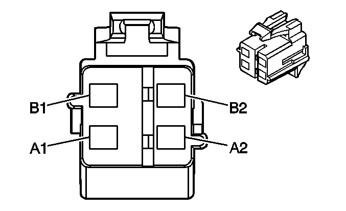
|
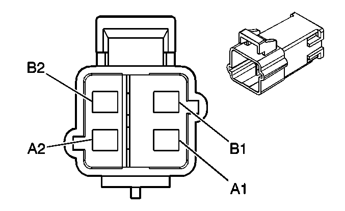
|
Connector Part Information
| Connector Part Information
|
Pin | Wire Color | Circuit No. | Function | Pin | Wire Color | Circuit No. | Function |
|---|---|---|---|---|---|---|---|
A1 | TN | 3021 | Steering Wheel Module Stage 1 High Control | A1 | TN | 3021 | Steering Wheel Module Stage 1 High Control |
A2 | BN | 3020 | Steering Wheel Module Stage 1 Low Control | A2 | BN | 3020 | Steering Wheel Module Stage 1 Low Control |
B1 | WH | 3023 | Steering Wheel Module Stage 2 High Control | B1 | WH | 3023 | Steering Wheel Module Stage 2 High Control |
B2 | PK | 3022 | Steering Wheel Module Stage 2 Low Control | B2 | PK | 3022 | Steering Wheel Module Stage 2 Low Control |
C276 - I/P Harness to the SIR Coil
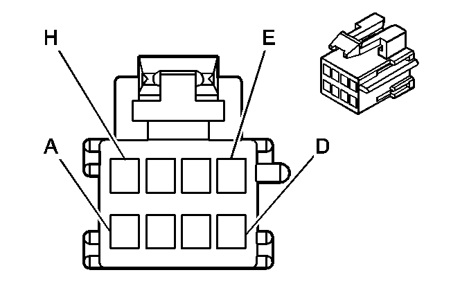
|
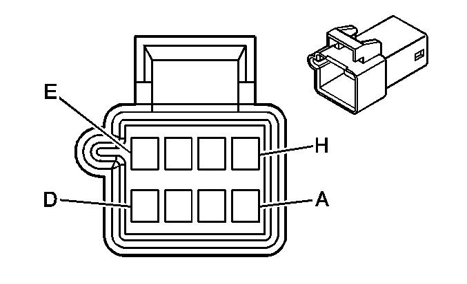
|
Connector Part Information
| Connector Part Information
|
Pin | Wire Color | Circuit No. | Function | Pin | Wire Color | Circuit No. | Function |
|---|---|---|---|---|---|---|---|
A | PK | 1339 | Ignition 1 Voltage | A | PK | 1339 | Ignition 1 Voltage |
B | GY | 1884 | Cruise Control Set/Coast and Resume/Accelerate Switch Signal | B | GY/BK | 1884 | Cruise Control Set/Coast and Resume/Accelerate Switch Signal |
C | D-BU | 1796 | Steering Wheel Controls Signal (UK3) | C | D-BU | 1796 | Steering Wheel Controls Signal (UK3) |
D | WH/BK | 644 | 10-Volt Reference (UK3) | D | WH/BK | 644 | 10-Volt Reference (UK3) |
E | BK/WH | 151 | Ground | E | BK/WH | 151 | Ground |
F | TN | 28 | Horn Relay Control | F | TN | 28 | Horn Relay Control |
G | -- | -- | Not Used | G | -- | -- | Not Used |
H | GY | 8 | I/P Lamps Dimmer Switch Signal | H | GY | 8 | I/P Lamps Dimmer Switch Signal |
C277 - SIR Coil to the Steering Wheel Control Switches Harness (3 Spoke)
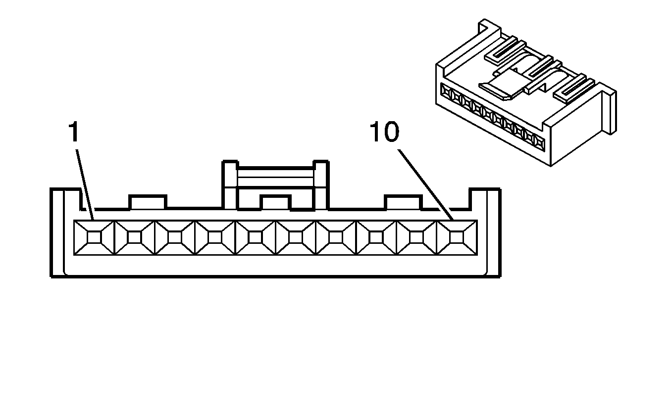
|
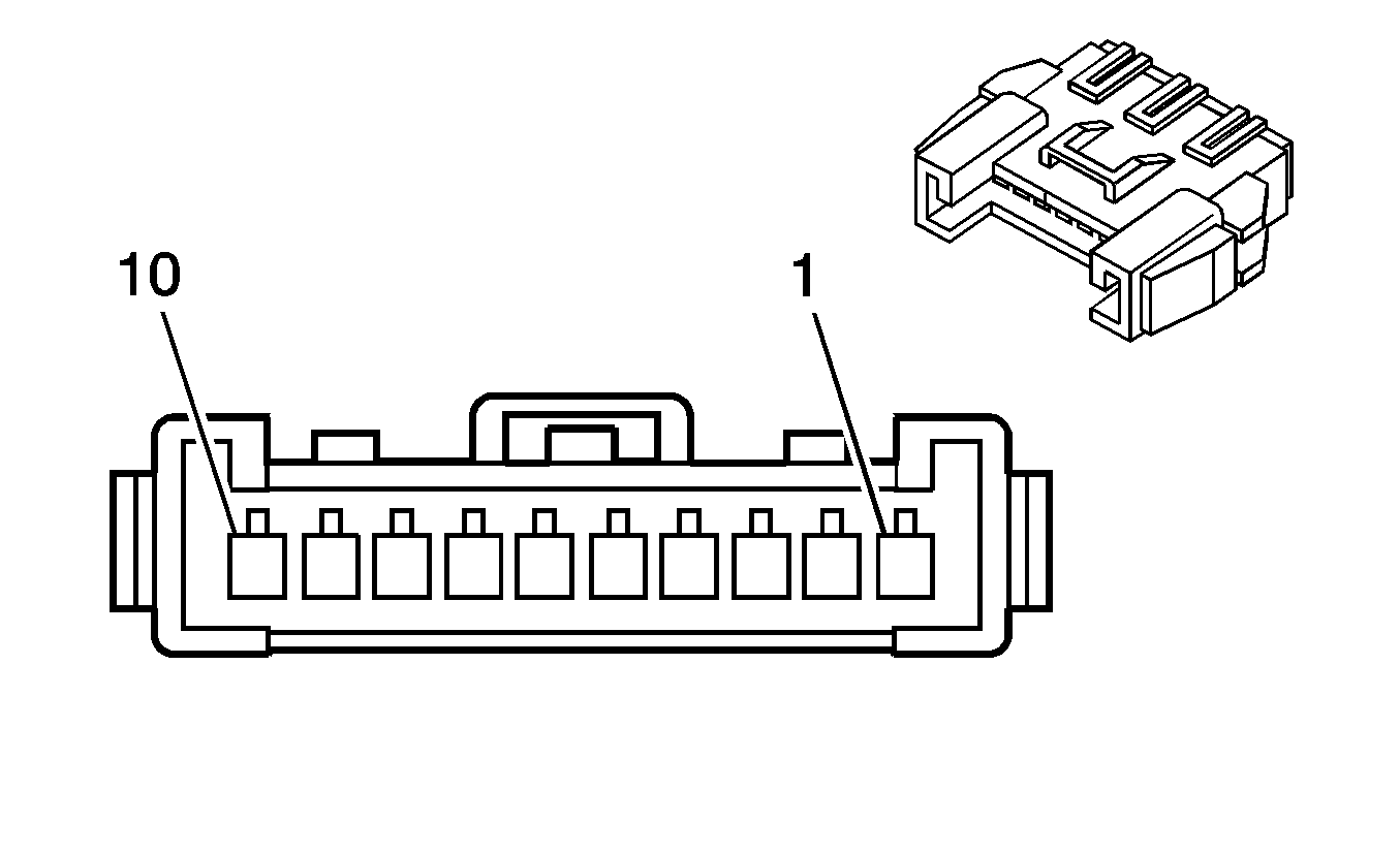
|
Connector Part Information
| Connector Part Information
|
Pin | Wire Color | Circuit No. | Function | Pin | Wire Color | Circuit No. | Function |
|---|---|---|---|---|---|---|---|
1 | PK | 1339 | Ignition 1 Voltage | 1 | PK | 1339 | Ignition 1 Voltage |
2 | GY/BK | 1884 | Cruise Control Set/Coast and Resume/Accelerate Switch Signal | 2 | BK/WH | 1884 | Cruise Control Set/Coast and Resume/Accelerate Switch Signal |
3 | D-BU | 1796 | Steering Wheel Controls Signal (UK3) | 3 | D-BU | 1796 | Steering Wheel Controls Signal (UK3) |
4 | WH/BK | 644 | 10-Volt Reference (UK3) | 4 | WH/BK | 644 | 10-Volt Reference (UK3) |
5 | BK/WH | 151 | Ground | 5 | BK | 151 | Ground |
6 | TN | 28 | Horn Relay Control | 6 | TN | 28 | Horn Relay Control |
7 | -- | -- | Not Used | 7 | -- | -- | Not Used |
8 | GY | 8 | I/P Lamps Dimmer Switch Signal | 8 | GY | 8 | I/P Lamps Dimmer Switch Signal |
9-10 | -- | -- | Not Used | 9-10 | -- | -- | Not Used |
C277 - SIR Coil to the Steering Wheel Control Switches Harness (4 Spoke)

|

|
Connector Part Information
| Connector Part Information
|
Pin | Wire Color | Circuit No. | Function | Pin | Wire Color | Circuit No. | Function |
|---|---|---|---|---|---|---|---|
A | PK | 1339 | Ignition 1 Voltage | A | PK | 1339 | Ignition 1 Voltage |
B | GY | 1884 | Cruise Control Set/Coast and Resume/Accelerate Switch Signal | B | GY | 1884 | Cruise Control Set/Coast and Resume/Accelerate Switch Signal |
C | D-BU | 1796 | Steering Wheel Controls Signal (UK3) | C | D-BU | 1796 | Steering Wheel Controls Signal (UK3) |
D-BU | 1796 | Steering Wheel Controls Signal (UK3) | |||||
D | WH/BK | 644 | 10-Volt Reference (UK3) | D | WH/BK | 644 | 10-Volt Reference (UK3) |
E | BK/WH | 151 | Ground | E | BK/WH | 151 | Ground |
BK/WH | 151 | Ground | |||||
F | TN | 28 | Horn Relay Control | F | TN | 28 | Horn Relay Control |
G | -- | -- | Not Used | G | -- | -- | Not Used |
H | GY | 8 | I/P Lamps Dimmer Switch Signal | H | GY/WH | 8 | I/P Lamps Dimmer Switch Signal |
GY/WH | 8 | I/P Lamps Dimmer Switch Signal |
C300 - Body Harness to the Headliner Harness
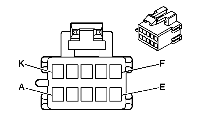
|
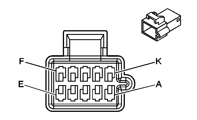
|
Connector Part Information
| Connector Part Information
|
Pin | Wire Color | Circuit No. | Function | Pin | Wire Color | Circuit No. | Function |
|---|---|---|---|---|---|---|---|
A | WH | 156 | Courtesy Lamps Switch Signal | A | WH | 156 | Courtesy Lamps Switch Signal |
B | BK | 750 | Ground | B | BK | 750 | Ground |
C | OG | 1732 | Courtesy Lamps Supply Voltage | C | OG | 1732 | Courtesy Lamps Supply Voltage |
D | YE | 43 | Accessory Voltage | D | YE | 43 | Accessory Voltage |
E | YE | 543 | Accessory Voltage | E | YE | 543 | Accessory Voltage |
F | L-GN | 24 | Backup Lamps Supply Voltage | F | L-GN | 24 | Backup Lamps Supply Voltage |
G | -- | -- | Not Used | G | -- | -- | Not Used |
H | BK | 750 | Ground | H | BK | 750 | Ground |
J | L-GN/BK | 735 | Ambient Air Temperature Sensor Signal | J | L-GN/BK | 735 | Ambient Air Temperature Sensor Signal |
K | GY | 720 | Low Reference | K | GY | 720 | Low Reference |
C301 - Body Harness to the Console Harness
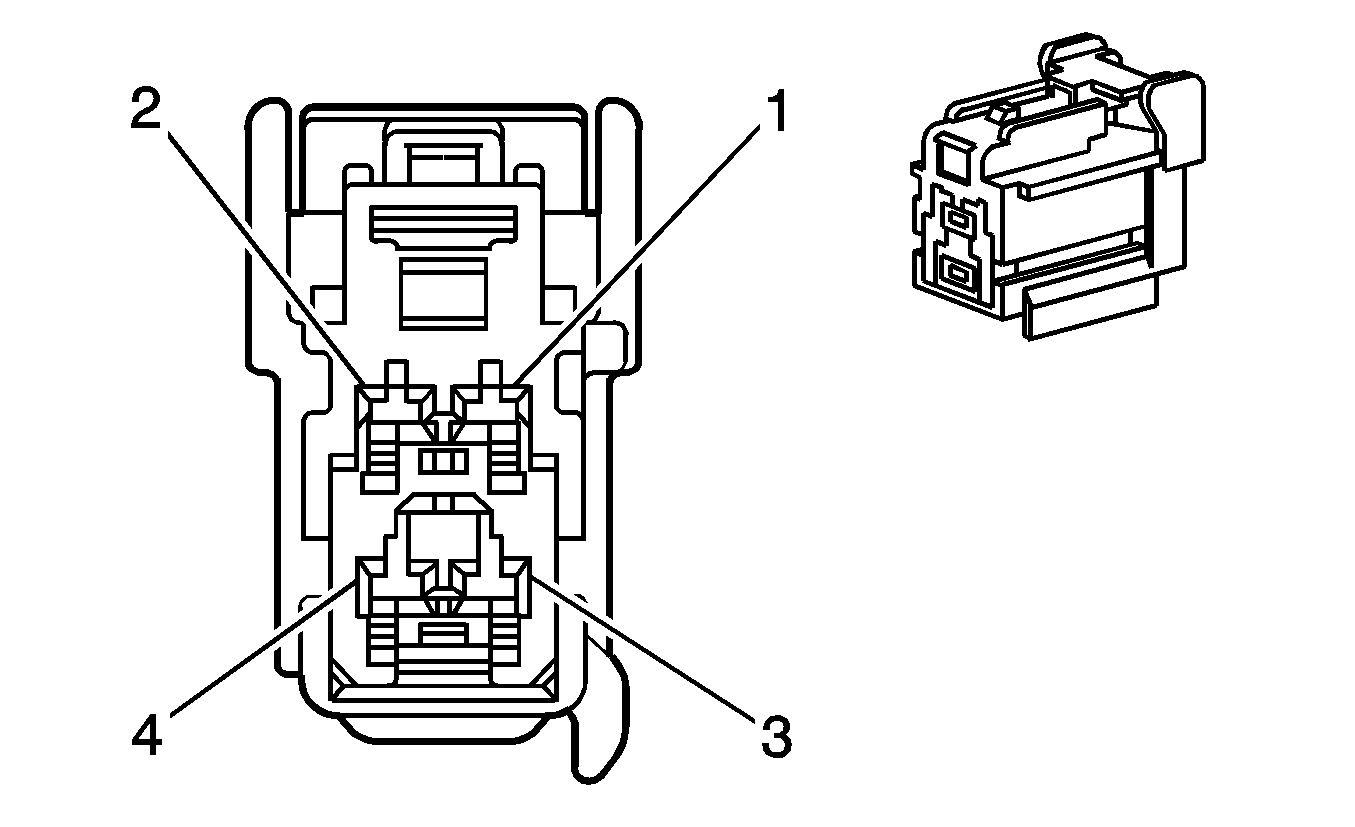
|
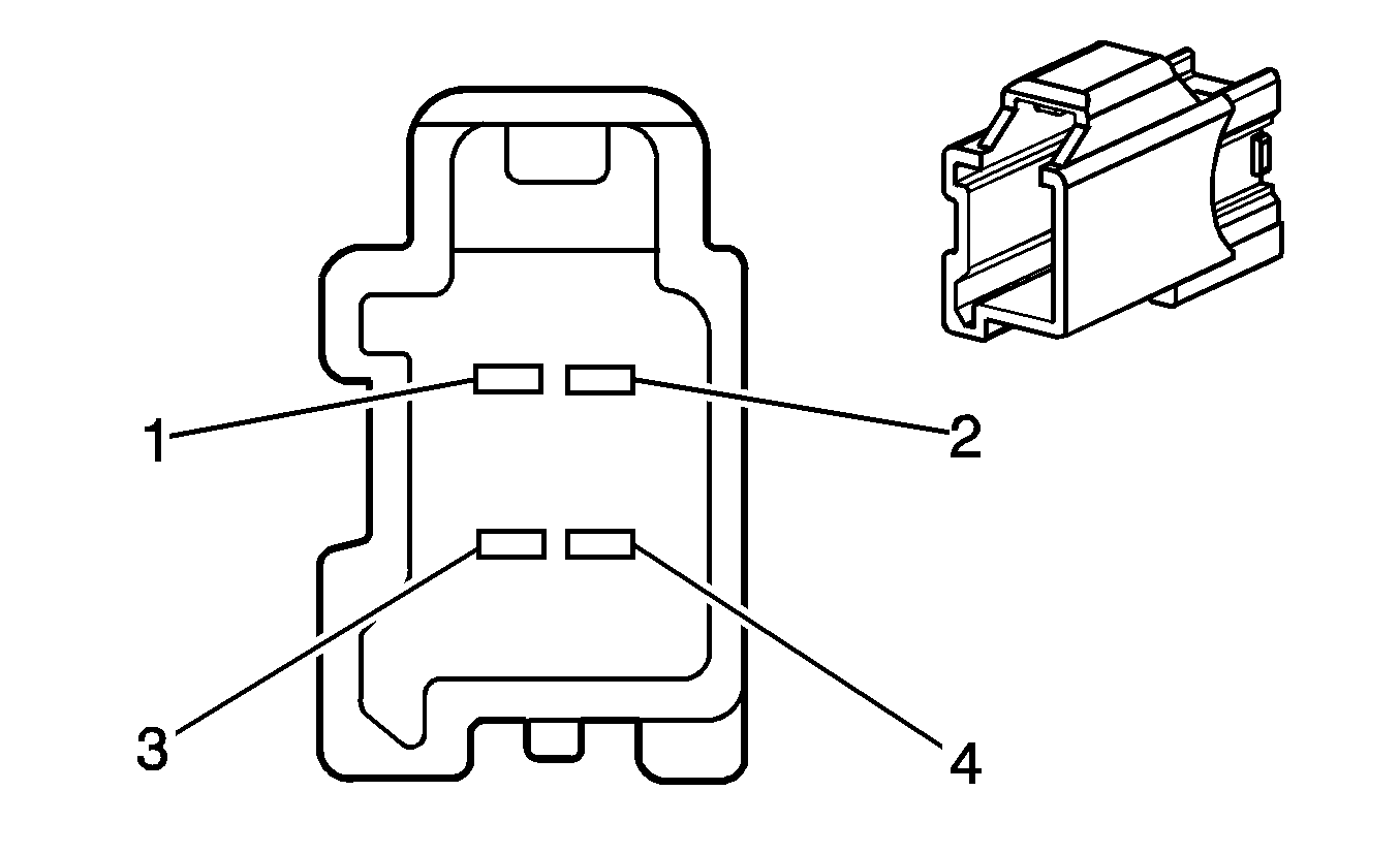
|
Connector Part Information
| Connector Part Information
|
Pin | Wire Color | Circuit No. | Function | Pin | Wire Color | Circuit No. | Function |
|---|---|---|---|---|---|---|---|
1 | RD/WH | 840 | Ignition 1 Voltage | 1 | RD/WH | 840 | Ignition 1 Voltage |
2 | BK | 650 | Ground | 2 | BK | 650 | Ground |
3 | RD/WH | 340 | Ignition 1 Voltage | 3 | RD/WH | 340 | Ignition 1 Voltage |
4 | BK | 650 | Ground | 4 | BK | 650 | Ground |
C302 - Headliner Harness to the Sunroof Harness (CF5)
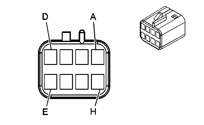
|
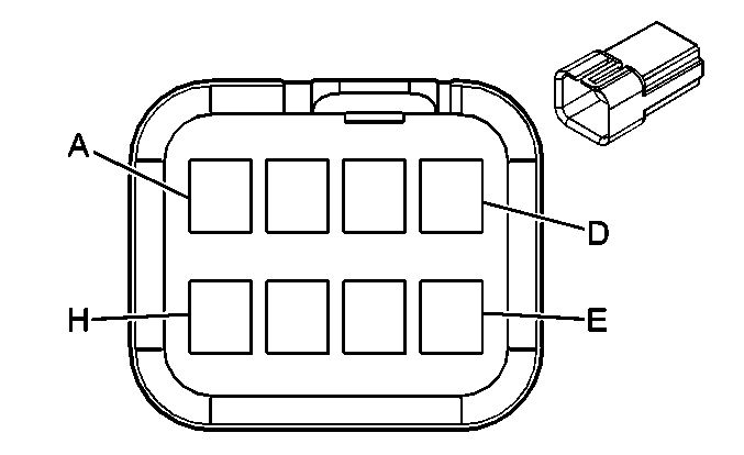
|
Connector Part Information
| Connector Part Information
|
Pin | Wire Color | Circuit No. | Function | Pin | Wire Color | Circuit No. | Function |
|---|---|---|---|---|---|---|---|
A | BN | 100 | Sunroof Switch Open Signal | A | BN | 100 | Sunroof Switch Open Signal |
B | D-GN | 2074 | Sunroof Switch Express Signal | B | D-GN | 2074 | Sunroof Switch Express Signal |
C | OG/BK | 144 | Sunroof Switch Open Vent Signal | C | OG/BK | 144 | Sunroof Switch Open Vent Signal |
D | D-BU | 128 | Low Reference | D | D-BU | 128 | Low Reference |
E | YE | 543 | Accessory Voltage | E | OG | 580 | Accessory Voltage |
F | BK | 750 | Ground | F | BK | 750 | Ground |
G-H | -- | -- | Not Used | G-H | -- | -- | Not Used |
C303 - Headliner Jumper Harness to the I/P Harness (UE1)
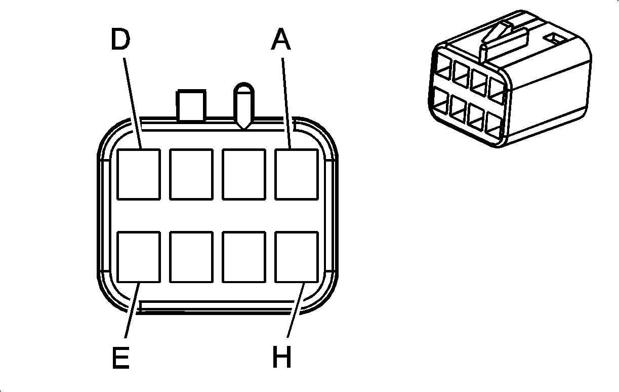
|

|
Connector Part Information
| Connector Part Information
|
Pin | Wire Color | Circuit No. | Function | Pin | Wire Color | Circuit No. | Function |
|---|---|---|---|---|---|---|---|
A | YE/BK | 2516 | Keypad Green LED Signal | A | YE/BK | 2516 | Keypad Green LED Signal |
B | L-GN/BK | 2515 | Keypad Supply Voltage | B | L-GN/BK | 2515 | Keypad Supply Voltage |
C | D-GN/WH | 2514 | Keypad Signal | C | D-GN/WH | 2514 | Keypad Signal |
D | BN/WH | 2517 | Keypad Red LED Signal | D | BN/WH | 2517 | Keypad Red LED Signal |
E | GY | 655 | Cellular Microphone Signal | E | GY | 655 | Cellular Microphone Signal |
F | D-GN | 1489 | Drain Wire | F | GY | 1489 | Drain Wire |
G-H | -- | -- | Not Used | G-H | -- | -- | Not Used |
C304 - I/P Harness to the Shifter Harness
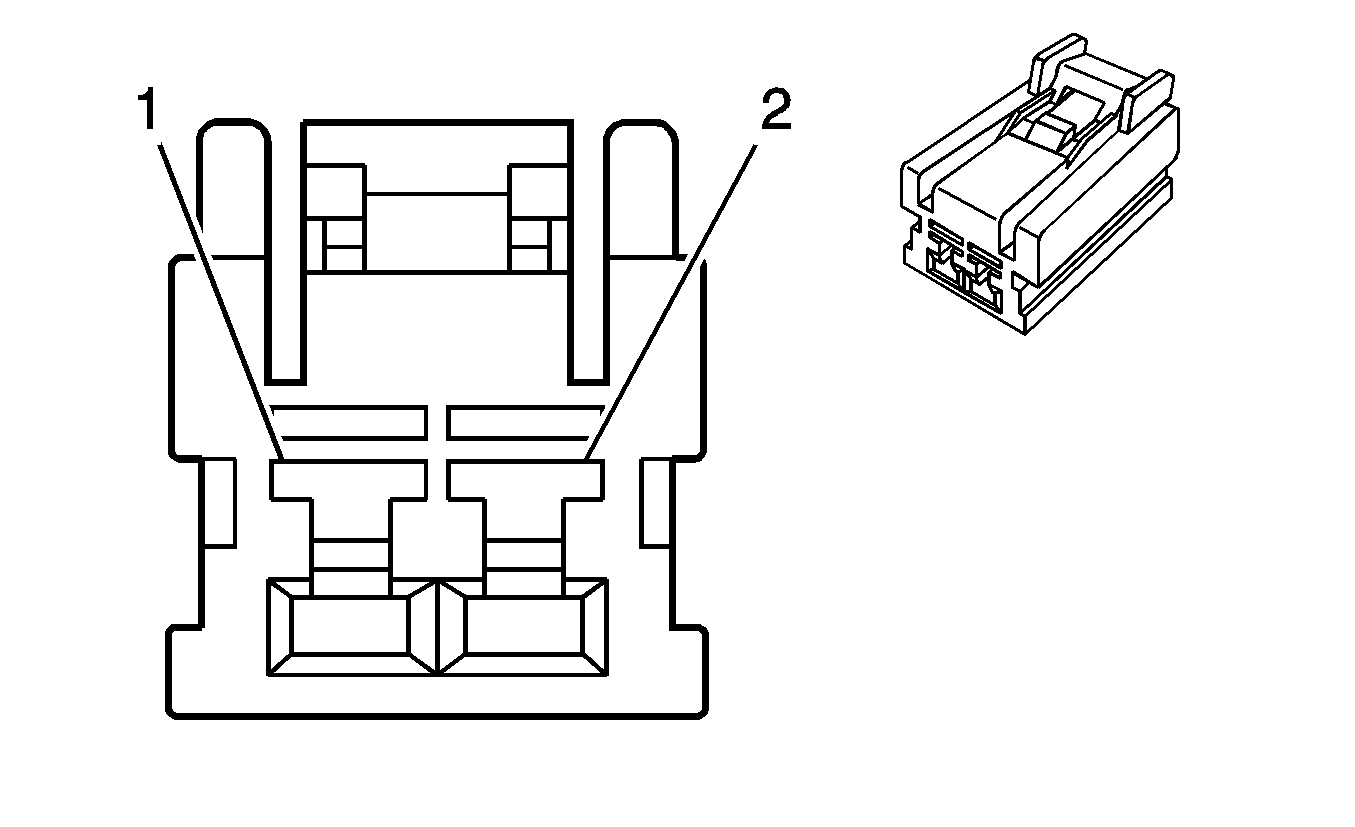
|

|
Connector Part Information
| Connector Part Information
|
Pin | Wire Color | Circuit No. | Function | Pin | Wire Color | Circuit No. | Function |
|---|---|---|---|---|---|---|---|
1 | TN/WH | 816 | A/T Shift Lock Solenoid Supply Voltage | 1 | WH | 816 | A/T Shift Lock Solenoid Supply Voltage |
2 | PK | 139 | Ignition 1 Voltage | 2 | PK | 139 | Ignition 1 Voltage |
C305 - Body Harness to the Driver Seat Harness (AG1/KA1)
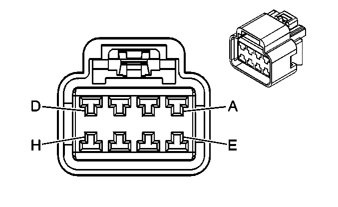
|
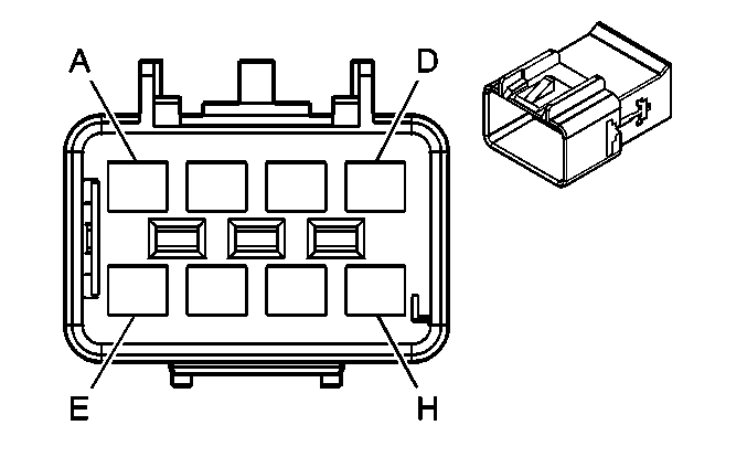
|
Connector Part Information
| Connector Part Information
|
Pin | Wire Color | Circuit No. | Function | Pin | Wire Color | Circuit No. | Function |
|---|---|---|---|---|---|---|---|
A | RD/WH | 1540 | Battery Positive Voltage | A | RD/WH | 1540 | Battery Positive Voltage |
B | BN | 141 | Ignition 3 Voltage | B | BN | 141 | Ignition 3 Voltage |
C | PK | 1501 | Driver Heated Seat High/Low Signal | C | PK | 1501 | Driver Heated Seat High/Low Signal |
D | BK | 650 | Ground | D | BK | 650 | Ground |
E | BK | 650 | Ground | E | BK | 650 | Ground |
F | RD/BK | 542 | Battery Positive Voltage | F | RD/BK | 542 | Battery Positive Voltage |
G | D-GN | 5016 | Seat Belt Switch - Left - Signal | G | TN/WH | 5016 | Seat Belt Switch - Left - Signal |
H | BK | 650 | Ground | H | D-BU | 650 | Ground |
C306 - Body Harness to the Front Passenger Seat Harness (KA1)
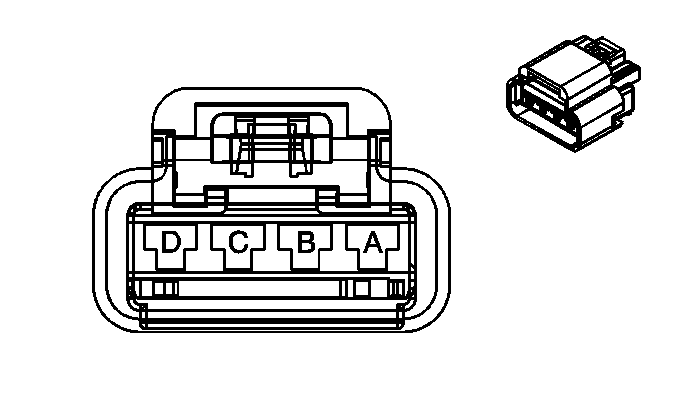
|
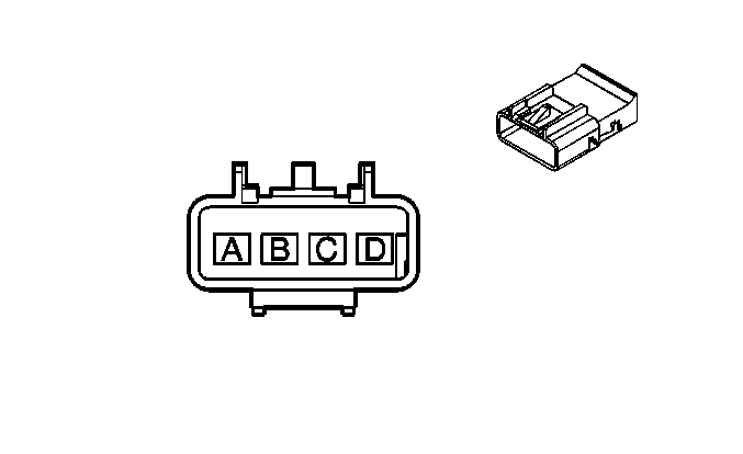
|
Connector Part Information
| Connector Part Information
|
Pin | Wire Color | Circuit No. | Function | Pin | Wire Color | Circuit No. | Function |
|---|---|---|---|---|---|---|---|
A | RD/WH | 1540 | Battery Positive Voltage | A | RD/WH | 1540 | Battery Positive Voltage |
B | BN | 141 | Ignition 3 Voltage | B | BN | 141 | Ignition 3 Voltage |
C | PK/BK | 1503 | Front Passenger Heated Seat High/Low Signal | C | PK/BK | 1503 | Front Passenger Heated Seat High/Low Signal |
D | BK | 650 | Ground | D | BK | 650 | Ground |
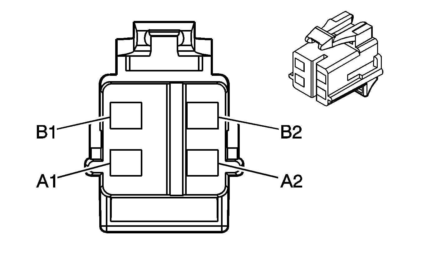
C307 - Roof Rail Harness to the I/P Harness (ASF)
|

|
Connector Part Information
| Connector Part Information
|
Pin | Wire Color | Circuit No. | Function | Pin | Wire Color | Circuit No. | Function |
|---|---|---|---|---|---|---|---|
A1 | YE | 2131 | Side Impact Sensing Module - Left - Voltage | A1 | YE | 2131 | Side Impact Sensing Module - Left - Voltage |
A2 | WH | 2132 | Side Impact Sensing Module - Left - Signal | A2 | WH | 2132 | Side Impact Sensing Module - Left - Signal |
B1 | TN | 2133 | Side Impact Sensing Module - Right - Voltage | B1 | TN | 2133 | Side Impact Sensing Module - Right - Voltage |
B2 | D-GN | 2134 | Side Impact Sensing Module - Right - Signal | B2 | D-GN | 2134 | Side Impact Sensing Module - Right - Signal |
C308 - Roof Rail Module Harness to the I/P Harness (ASF)

|

|
Connector Part Information
| Connector Part Information
|
Pin | Wire Color | Circuit No. | Function | Pin | Wire Color | Circuit No. | Function |
|---|---|---|---|---|---|---|---|
A1 | YE/BK | 5021 | Roof Rail Module - Right - High Control | A1 | YE/BK | 5021 | Roof Rail Module - Right - High Control |
A2 | WH/BK | 5022 | Roof Rail Module - Right - Low Control | A2 | WH/BK | 5022 | Roof Rail Module - Right - Low Control |
B1 | PU/WH | 5019 | Roof Rail Module - Left - High Control | B1 | PU/WH | 5019 | Roof Rail Module - Left - High Control |
B2 | PK | 5020 | Roof Rail Module - Left - Low Control | B2 | PK | 5020 | Roof Rail Module - Left - Low Control |
C310 - Driver Seat Jumper Harness to the Driver Seat Harness (AG1/KA1)

|

|
Connector Part Information
| Connector Part Information
|
Pin | Wire Color | Circuit No. | Function | Pin | Wire Color | Circuit No. | Function |
|---|---|---|---|---|---|---|---|
A-D | -- | -- | Not Used | A-D | -- | -- | Not Used |
E | BK | 650 | Ground | E | BK | 650 | Ground |
F | RD/BK | 542 | Battery Positive Voltage | F | RD/BK | 542 | Battery Positive Voltage |
G | TN/WH | 5016 | Seat Belt Switch - Left - Signal | G | TN/WH | 5016 | Seat Belt Switch - Left - Signal |
H | D-BU | 650 | Ground | H | D-BU | 650 | Ground |
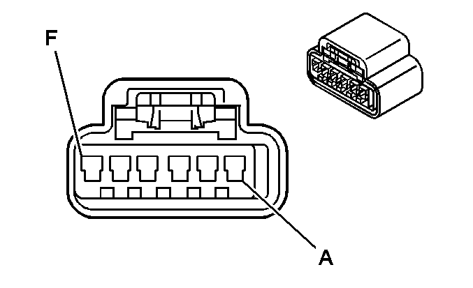
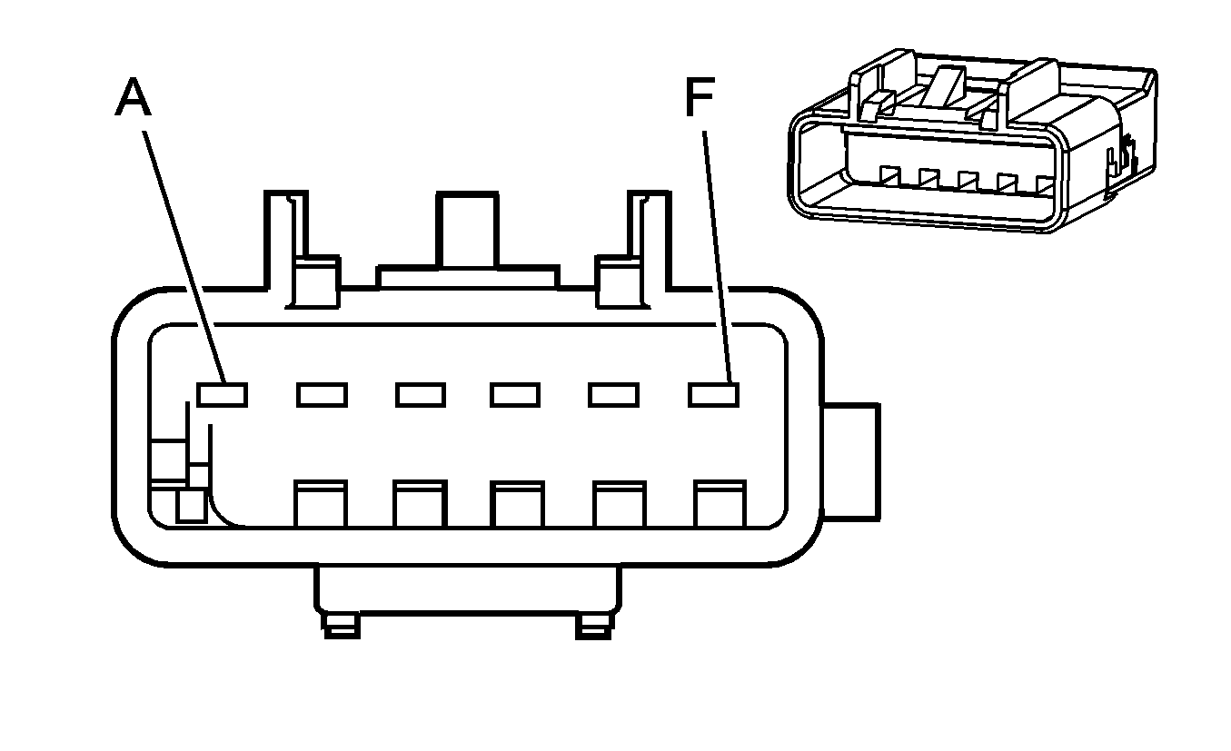
C311 - I/P Harness to the Body Harness
|
|
Connector Part Information
| Connector Part Information
|
Pin | Wire Color | Circuit No. | Function | Pin | Wire Color | Circuit No. | Function |
|---|---|---|---|---|---|---|---|
A | TN/WH | 2118 | Seat Belt Pretensioner - Left - High Control | A | TN/WH | 2118 | Seat Belt Pretensioner - Left - High Control |
B | OG/BK | 2119 | Seat Belt Pretensioner - Left - Low Control | B | OG/BK | 2119 | Seat Belt Pretensioner - Left - Low Control |
C-D | -- | -- | Not Used | C-D | -- | -- | Not Used |
E | L-GN | 2116 | Seat Belt Pretensioner - Right - High Control | E | L-GN | 2116 | Seat Belt Pretensioner - Right - High Control |
F | OG | 2117 | Seat Belt Pretensioner - Right - Low Control | F | OG | 2117 | Seat Belt Pretensioner - Right - Low Control |
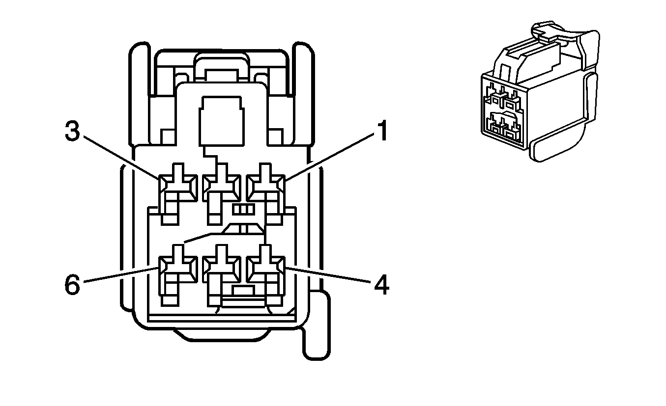
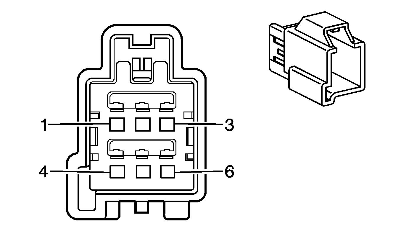
C312 - Body Harness to the Trailer Connector Adapter Harness (V92)
|
|
Connector Part Information
| Connector Part Information
|
Pin | Wire Color | Circuit No. | Function | Pin | Wire Color | Circuit No. | Function |
|---|---|---|---|---|---|---|---|
1 | OG | 5186 | Right Turn Signal Lamps Supply Voltage | 1 | YE | 5186 | Right Turn Signal Lamps Supply Voltage |
2 | YE | 5187 | Left Turn Signal Lamps Supply Voltage | 2 | D-GN | 5187 | Left Turn Signal Lamps Supply Voltage |
3 | BN | 9 | Park Lamps Supply Voltage | 3 | BN | 9 | Park Lamps Supply Voltage |
4 | L-BU | 20 | Stop Lamp Switch Signal | 4 | RD | 20 | Stop Lamp Switch Signal |
5 | BK | 750 | Ground | 5 | WH | 750 | Ground |
6 | RD/WH | 1840 | Battery Positive Voltage | 6 | RD/WH | 1840 | Battery Positive Voltage |
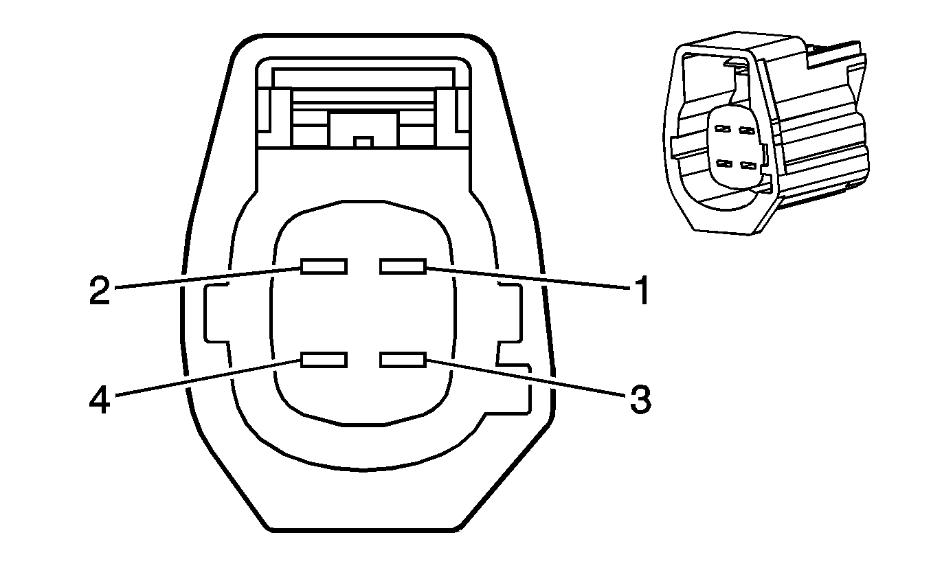
C313 - Trailer Connector Adapter Harness to the Trailer Hitch Harness (V92)
|

|
Connector Part Information
| Connector Part Information
|
Pin | Wire Color | Circuit No. | Function | Pin | Wire Color | Circuit No. | Function |
|---|---|---|---|---|---|---|---|
1 | YE | 1618 | Left Turn Signal Lamps Supply Voltage | 1 | YE | 1618 | Left Turn Signal Lamps Supply Voltage |
2 | D-GN | 1619 | Right Turn Signal Lamps Supply Voltage | 2 | D-GN | 1619 | Right Turn Signal Lamps Supply Voltage |
3 | BN | 2109 | Park Lamps Supply Voltage | 3 | BN | 2109 | Park Lamps Supply Voltage |
4 | WH | 750 | Ground | 4 | BK | 750 | Ground |
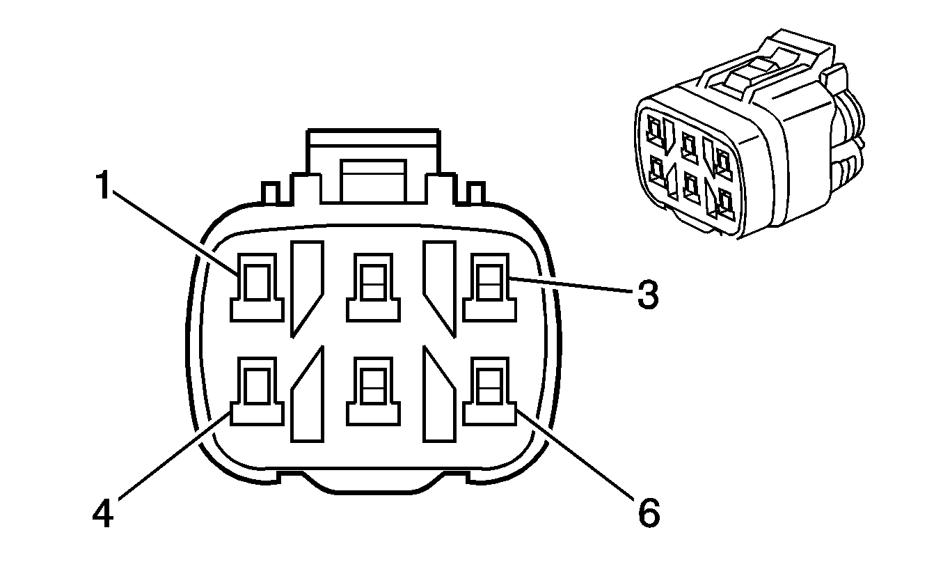
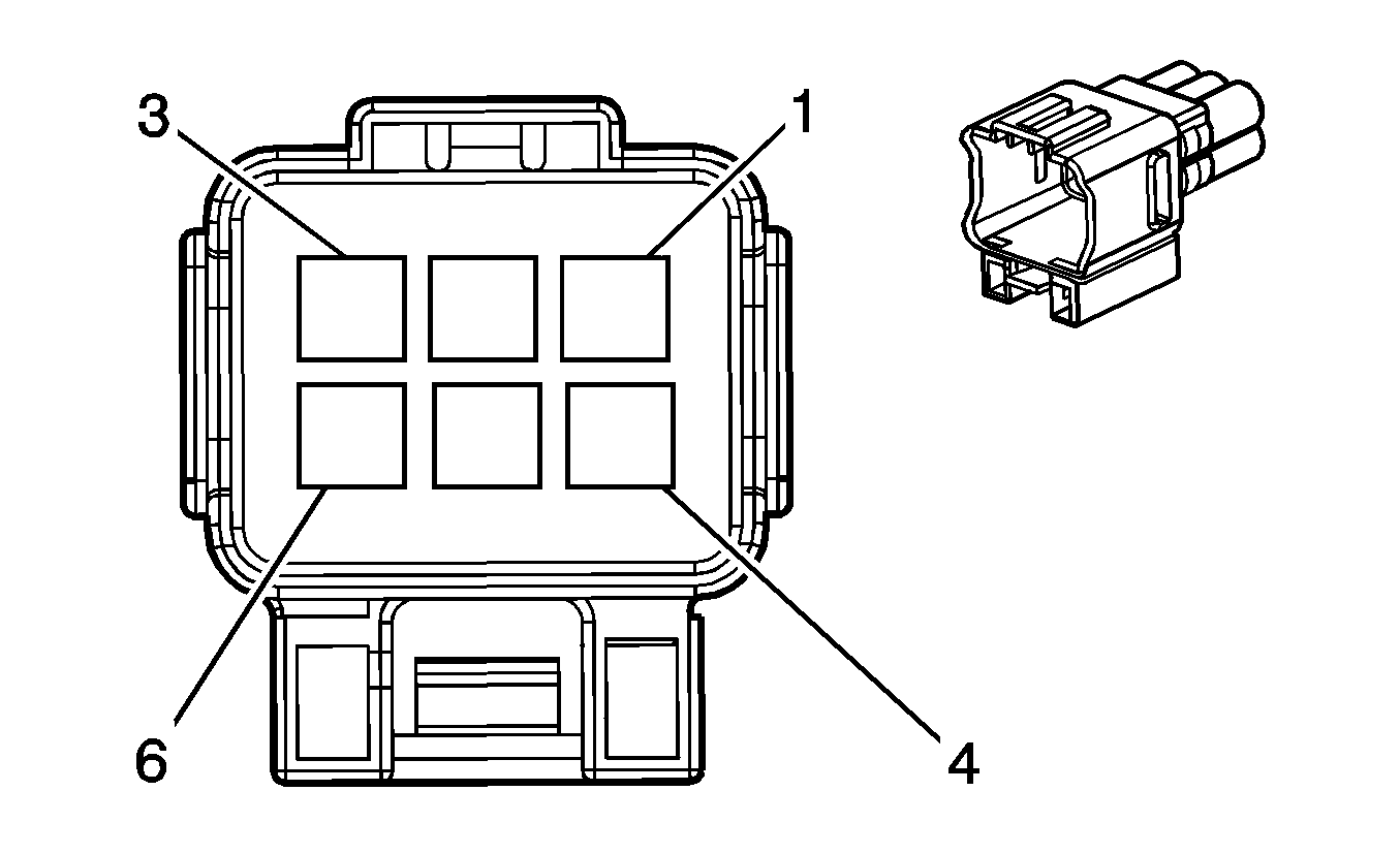
C400 - Body Harness to the LR Tail Lamp Harness
|
|
Connector Part Information
| Connector Part Information
|
Pin | Wire Color | Circuit No. | Function | Pin | Wire Color | Circuit No. | Function |
|---|---|---|---|---|---|---|---|
1 | YE | 618 | Left Rear Turn Signal Lamp Supply Voltage | 1 | D-GN | 618 | Left Rear Turn Signal Lamp Supply Voltage |
2 | BK | 750 | Ground | 2 | BK | 750 | Ground |
3 | -- | -- | Not Used | 3 | -- | -- | Not Used |
4 | BN | 9 | Park Lamp Supply Voltage | 4 | RD/BU | 9 | Park Lamp Supply Voltage |
5 | L-BU | 20 | Stop Lamp Switch Signal | 5 | GN/WH | 20 | Stop Lamp Switch Signal |
6 | L-GN | 24 | Backup Lamp Supply Voltage | 6 | RD | 24 | Backup Lamp Supply Voltage |
C401 - Body Harness to the RR Tail Lamp Harness

|

|
Connector Part Information
| Connector Part Information
|
Pin | Wire Color | Circuit No. | Function | Pin | Wire Color | Circuit No. | Function |
|---|---|---|---|---|---|---|---|
1 | D-GN | 619 | Right Rear Turn Signal Lamp Supply Voltage | 1 | D-GN | 619 | Right Rear Turn Signal Lamp Supply Voltage |
2 | BK | 850 | Ground | 2 | BK | 850 | Ground |
3 | -- | -- | Not Used | 3 | -- | -- | Not Used |
4 | BN | 9 | Park Lamp Supply Voltage | 4 | RD/BU | 9 | Park Lamp Supply Voltage |
5 | L-BU | 20 | Stop Lamp Switch Signal | 5 | GN/WH | 20 | Stop Lamp Switch Signal |
6 | L-GN | 24 | Backup Lamp Supply Voltage | 6 | RD | 24 | Backup Lamp Supply Voltage |
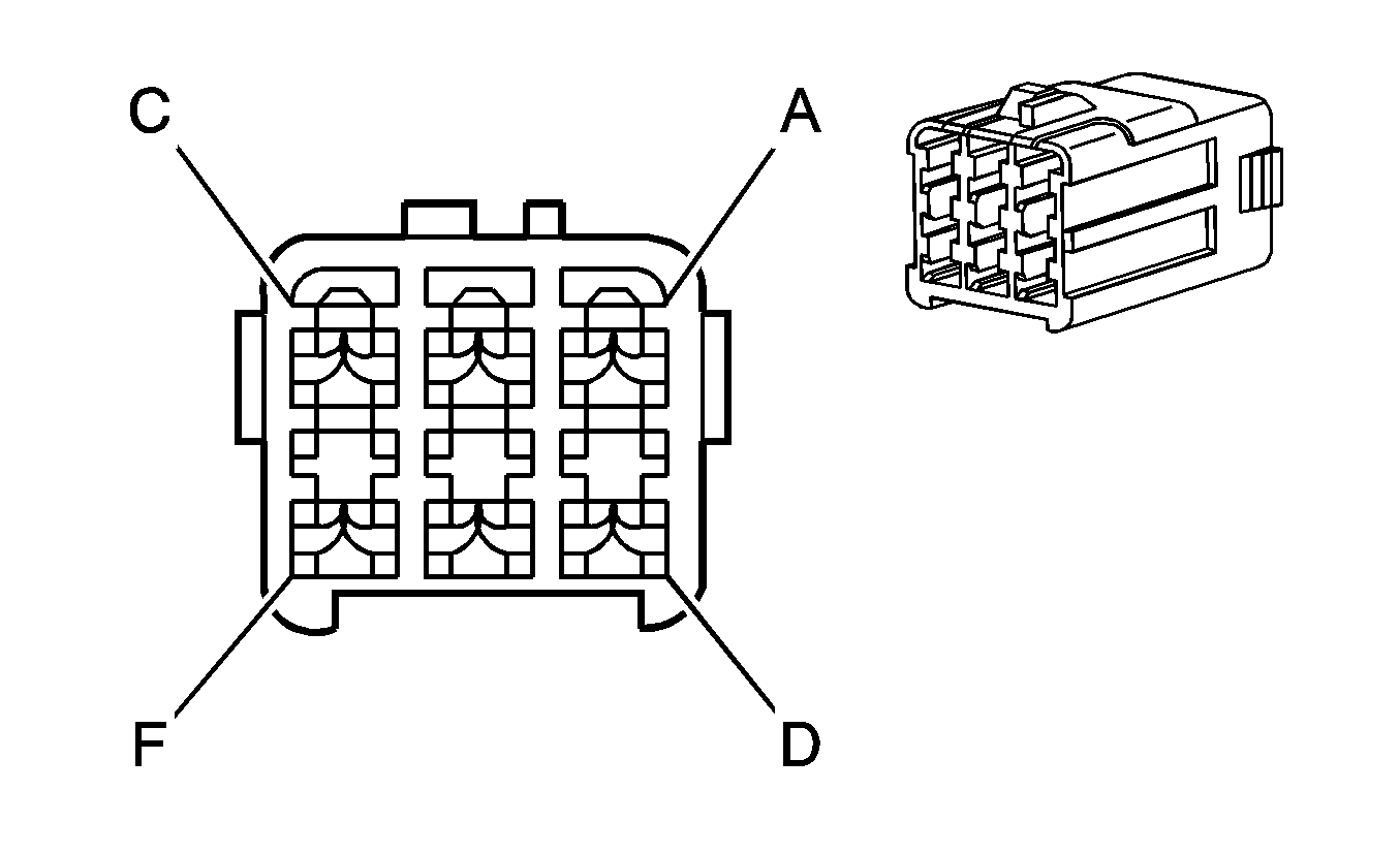
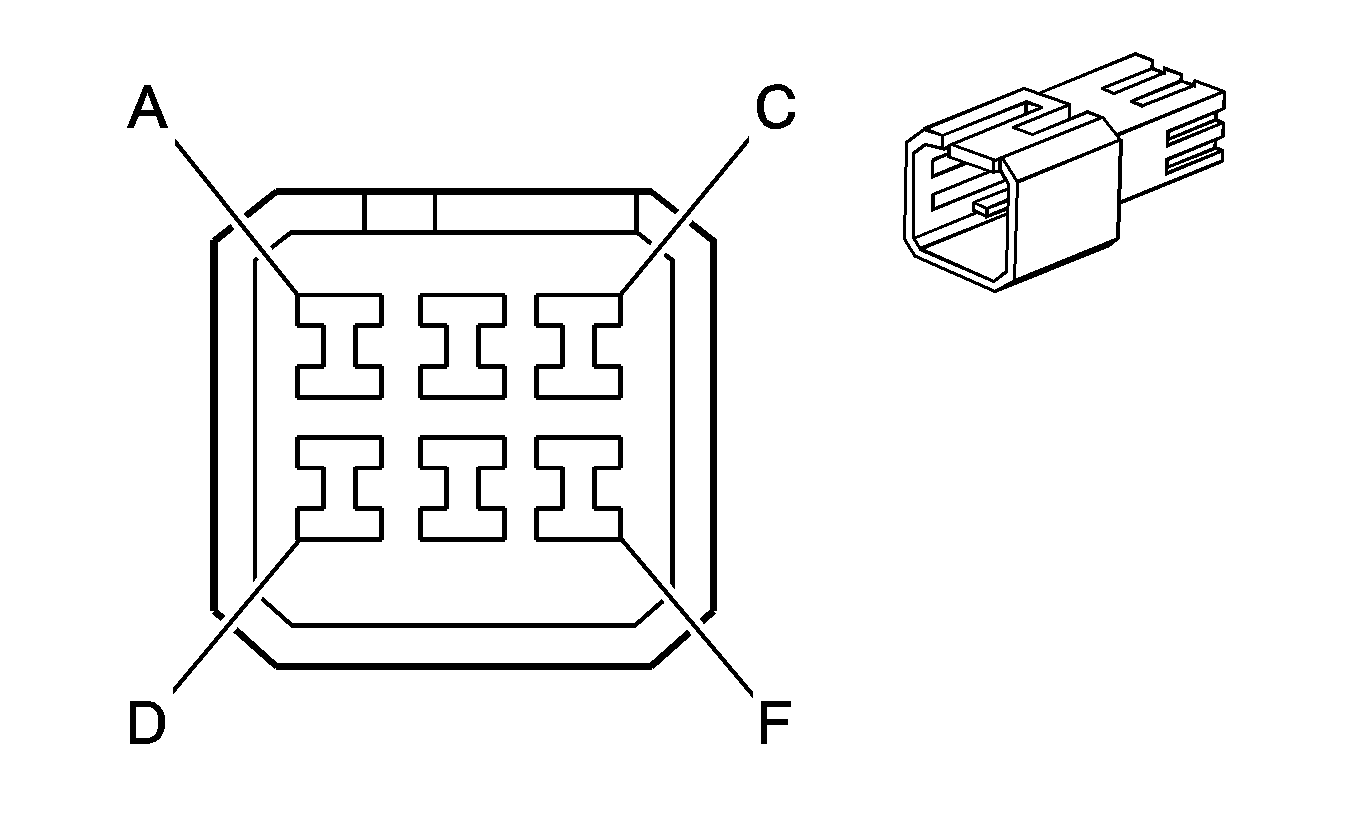
C402 - Liftgate Jumper Harness to the Body Harness
|
|
Connector Part Information
| Connector Part Information
|
Pin | Wire Color | Circuit No. | Function | Pin | Wire Color | Circuit No. | Function |
|---|---|---|---|---|---|---|---|
A | BN | 9 | Park Lamp Supply Voltage | A | BN | 9 | Park Lamp Supply Voltage |
B | GY | 295 | Door Lock Actuator Lock Control | B | GY | 295 | Door Lock Actuator Lock Control |
C | YE | 143 | Accessory Voltage | C | YE | 143 | Accessory Voltage |
D | WH | 393 | Rear Window Wiper Motor Control | D | WH | 393 | Rear Window Wiper Motor Control |
E | TN | 294 | Door Lock Actuator Unlock Control | E | TN | 294 | Door Lock Actuator Unlock Control |
F | OG/BK | 744 | Liftgate Ajar Switch Signal | F | OG/BK | 744 | Liftgate Ajar Switch Signal |
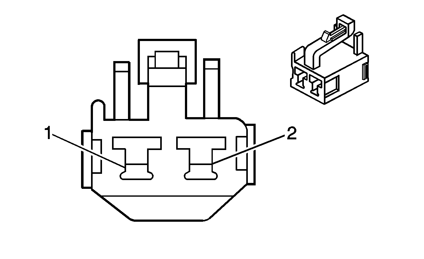
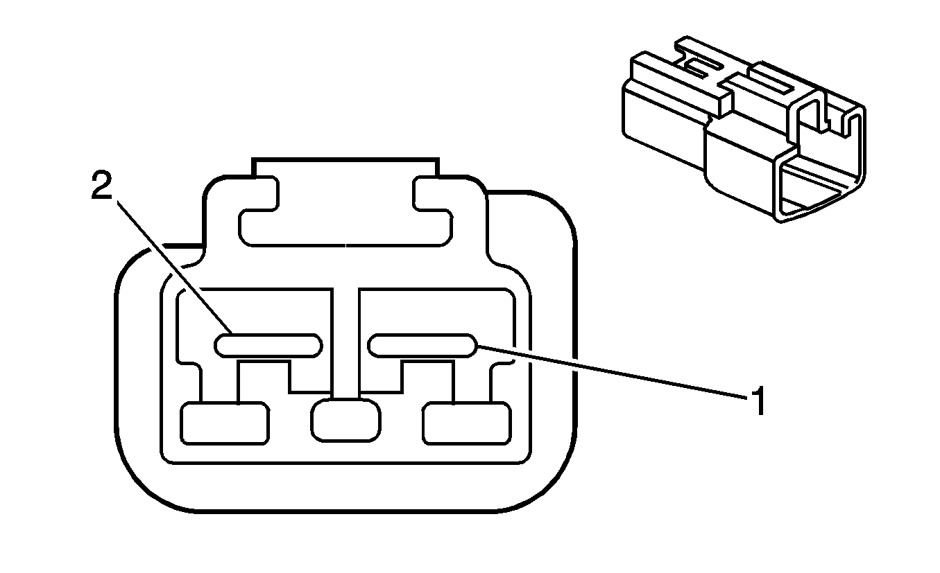
C403 - Liftgate Jumper Harness to the Body Harness
|
|
Connector Part Information
| Connector Part Information
|
Pin | Wire Color | Circuit No. | Function | Pin | Wire Color | Circuit No. | Function |
|---|---|---|---|---|---|---|---|
1 | PU | 293 | Rear Defogger Element Supply Voltage | 1 | PU | 293 | Rear Defogger Element Supply Voltage |
2 | BK | 750 | Ground | 2 | BK | 750 | Ground |
C404 - Body Harness to the Rear WSS Harness (JM4)
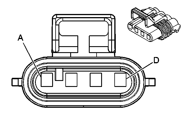
|
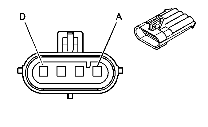
|
Connector Part Information
| Connector Part Information
|
Pin | Wire Color | Circuit No. | Function | Pin | Wire Color | Circuit No. | Function |
|---|---|---|---|---|---|---|---|
A | WH | 883 | Right Rear Wheel Speed Sensor Low Reference | A | BN | 883 | Right Rear Wheel Speed Sensor Low Reference |
B | BN | 882 | Right Rear Wheel Speed Sensor Signal | B | WH | 882 | Right Rear Wheel Speed Sensor Signal |
C | OG | 885 | Left Rear Wheel Speed Sensor Low Reference | C | BK | 885 | Left Rear Wheel Speed Sensor Low Reference |
D | TN | 884 | Left Rear Wheel Speed Sensor Signal | D | RD | 884 | Left Rear Wheel Speed Sensor Signal |
C406 - Body Harness to the Fuel Tank Harness
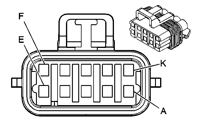
|
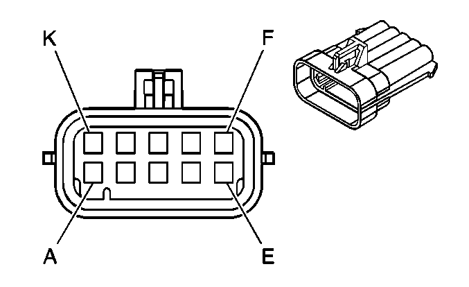
|
Connector Part Information
| Connector Part Information
|
Pin | Wire Color | Circuit No. | Function | Pin | Wire Color | Circuit No. | Function |
|---|---|---|---|---|---|---|---|
A | GY | 120 | Fuel Pump Supply Voltage | A | GY | 120 | Fuel Pump Supply Voltage |
B | BK | 850 | Ground | B | BK | 850 | Ground |
C | PU | 1589 | Fuel Level Sensor Signal | C | PU | 1589 | Fuel Level Sensor Signal |
D | -- | -- | Not Used | D | D-BU | 930 | Fuel Level Sensor Signal - Common |
E | GY | 2709 | 5-Volt Reference | E | GY | 2709 | 5-Volt Reference |
F | D-GN | 890 | Fuel Tank Pressure Sensor Signal | F | D-GN | 890 | Fuel Tank Pressure Sensor Signal |
G | TN | 2759 | Low Reference | G | BK | 2759 | Low Reference |
H | TN | 2759 | Low Reference | H | BK/WH | 2759 | Low Reference |
J | RD/WH | 1440 | Battery Positive Voltage | J | PK | 1440 | Battery Positive Voltage |
K | WH | 1310 | EVAP Canister Vent Solenoid Control | K | WH | 1310 | EVAP Canister Vent Solenoid Control |
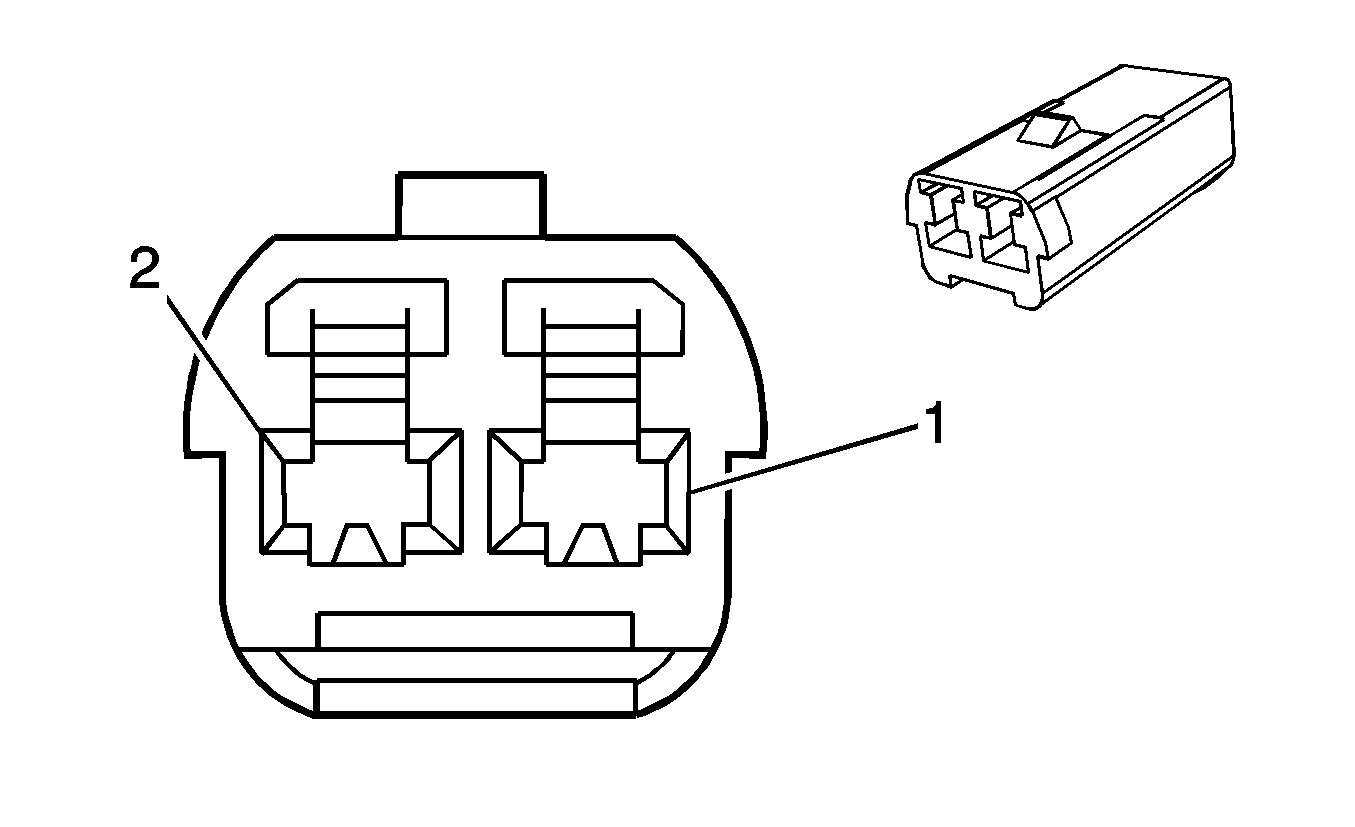
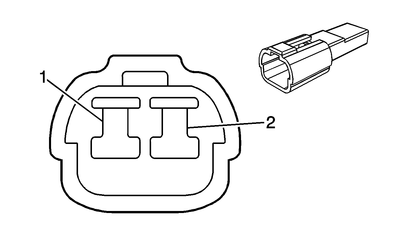
C408 - Body Harness to the CHMSL Jumper Harness
|
|
Connector Part Information
| Connector Part Information
|
Pin | Wire Color | Circuit No. | Function | Pin | Wire Color | Circuit No. | Function |
|---|---|---|---|---|---|---|---|
1 | L-BU | 20 | Stop Lamp Switch Signal | 1 | L-BU | 20 | Stop Lamp Switch Signal |
2 | BK | 850 | Ground | 2 | BK | 850 | Ground |
C410 - Roof Rail Harness to the LH Roof Rail Jumper Harness

|

|
Connector Part Information
| Connector Part Information
|
Pin | Wire Color | Circuit No. | Function | Pin | Wire Color | Circuit No. | Function |
|---|---|---|---|---|---|---|---|
1 | PU/WH | 5019 | LF Side Impact Module - High Control | 1 | D-GN | 5019 | LF Side Impact Module - High Control |
2 | PK | 5020 | LF Side Impact Module - High Control | 2 | WH | 5020 | LF Side Impact Module - High Control |
C411 - Roof Rail Harness to the RH Roof Rail Jumper Harness

|

|
Connector Part Information
| Connector Part Information
|
Pin | Wire Color | Circuit No. | Function | Pin | Wire Color | Circuit No. | Function |
|---|---|---|---|---|---|---|---|
1 | YE/BK | 5021 | LF Side Impact Module - High Control | 1 | D-GN | 5019 | LF Side Impact Module - High Control |
2 | WH/BK | 5022 | LF Side Impact Module - High Control | 2 | WH | 5020 | LF Side Impact Module - High Control |
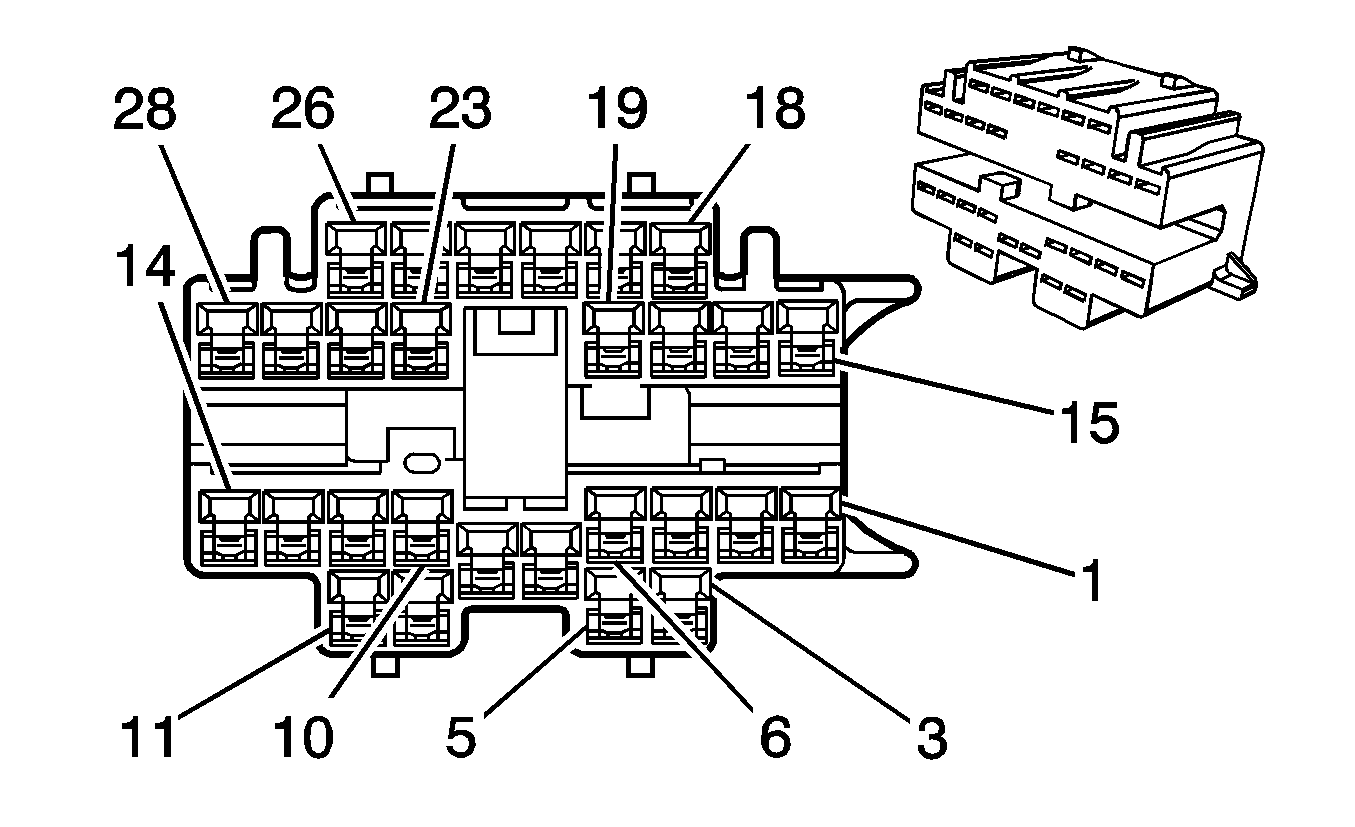
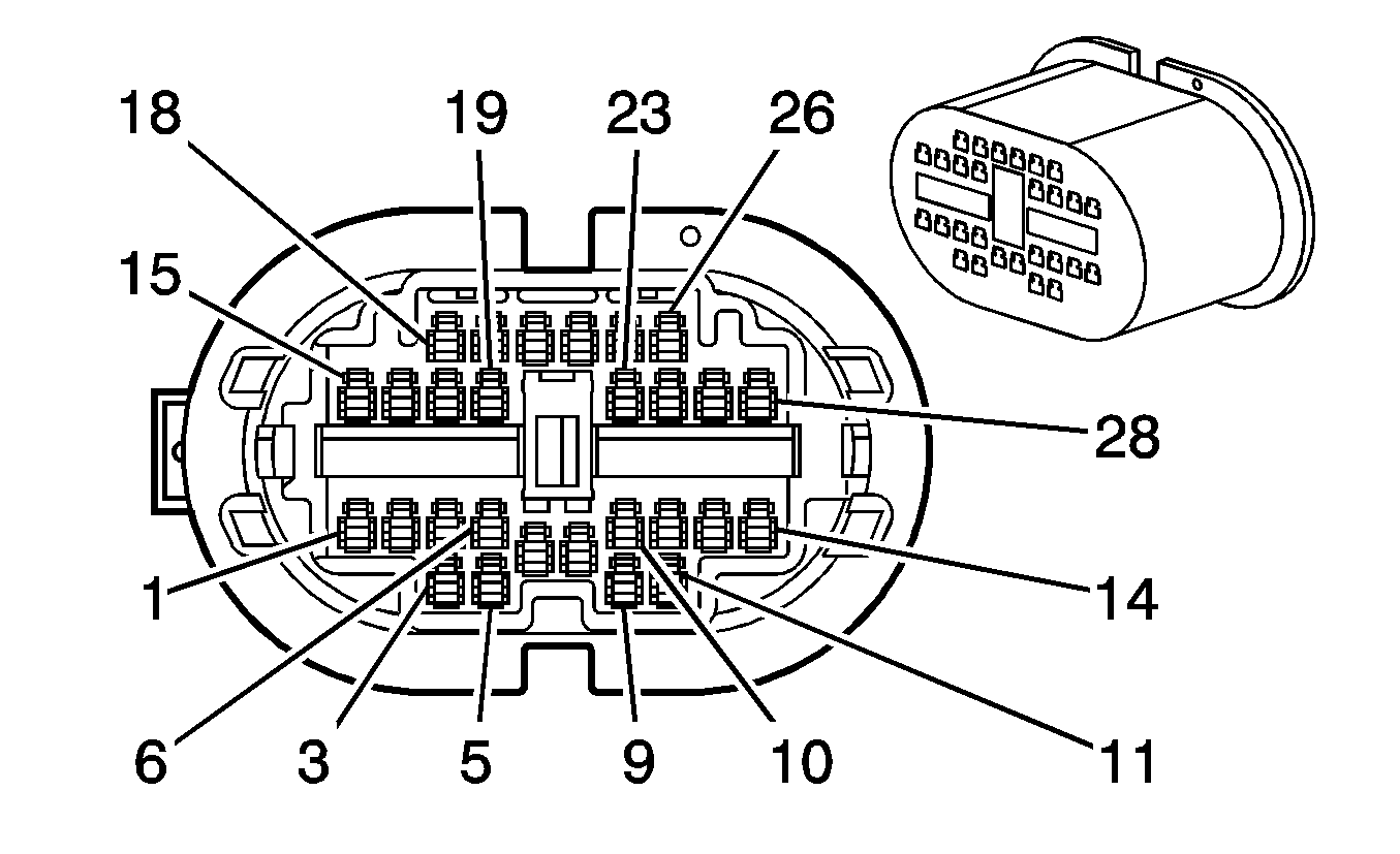
C500 - Body Harness to the LF Door Harness
|
|
Connector Part Information
| Connector Part Information
|
Pin | Wire Color | Circuit No. | Function | Pin | Wire Color | Circuit No. | Function |
|---|---|---|---|---|---|---|---|
1-2 | -- | -- | Not Used | 1-2 | -- | -- | Not Used |
3 | GY | 118 | Left Front Speaker Output (-) | 3 | TN | 118 | Left Front Speaker Output (-) |
4 | TN | 201 | Left Front Speaker Output (+) | 4 | GY | 201 | Left Front Speaker Output (+) |
5-6 | -- | -- | Not Used | 5-6 | -- | -- | Not Used |
7 | D-BU | 245 | Passenger Door Lock Switch Unlock Control | 7 | OG/BK | 245 | Passenger Door Lock Switch Unlock Control |
8 | L-BU | 244 | Passenger Door Lock Switch Lock Control | 8 | RD/BK | 244 | Passenger Door Lock Switch Lock Control |
9 | YE | 1496 | Mirror Motor Right/Up Control | 9 | YE | 1496 | Mirror Motor Right/Up Control |
10 | BK | 650 | Ground | 10 | BK | 650 | Ground |
11 | L-GN | 89 | Driver Mirror Motor Down Control | 11 | L-GN | 89 | Driver Mirror Motor Down Control |
12 | WH | 81 | Driver Mirror Motor Right Control | 12 | WH | 81 | Driver Mirror Motor Right Control |
13 | -- | -- | Not Used | 13 | BK | 746 | Not Used |
14-18 | -- | -- | Not Used | 14-18 | -- | -- | Not Used |
19 | GY/BK | 745 | Left Front Door Ajar Switch Signal | 19 | RD/BK | 745 | Left Front Door Ajar Switch Signal |
20 | -- | -- | Not Used | 20 | -- | -- | Not Used |
21 | RD/WH | 440 | Battery Positive Voltage | 21 | OG | 440 | Battery Positive Voltage |
22 | -- | -- | Not Used | 22 | -- | -- | Not Used |
23 | GY | 295 | Door Lock Actuator Lock Control | 23 | GY | 295 | Door Lock Actuator Lock Control |
24 | TN | 694 | Driver Door Lock Actuator Unlock Control | 24 | TN | 694 | Driver Door Lock Actuator Unlock Control |
25 | D-BU | 164 | Power Window Motor Left Front Up Control | 25 | D-BU | 164 | Power Window Motor Left Front Up Control |
26 | BN | 165 | Power Window Motor Left Front Down Control | 26 | BN | 165 | Power Window Motor Left Front Down Control |
27-28 | -- | -- | Not Used | 27-28 | -- | -- | Not Used |
C600 - Body Harness to the RF Door Harness

|

|
Connector Part Information
| Connector Part Information
|
Pin | Wire Color | Circuit No. | Function | Pin | Wire Color | Circuit No. | Function |
|---|---|---|---|---|---|---|---|
1-2 | -- | -- | Not Used | 1-2 | -- | -- | Not Used |
3 | D-GN | 117 | Right Front Speaker Output (-) | 3 | TN | 117 | Right Front Speaker Output (-) |
4 | L-GN | 200 | Right Front Speaker Output (+) | 4 | GY | 200 | Right Front Speaker Output (+) |
5-6 | -- | -- | Not Used | 5-6 | -- | -- | Not Used |
7 | D-BU | 245 | Passenger Door Lock Switch Unlock Control | 7 | OG/BK | 245 | Passenger Door Lock Switch Unlock Control |
8 | L-BU | 244 | Passenger Door Lock Switch Lock Control | 8 | RD/BK | 244 | Passenger Door Lock Switch Lock Control |
9 | YE | 1496 | Mirror Motor Right/Up Control | 9 | YE | 1496 | Mirror Motor Right/Up Control |
10 | GY | 295 | Door Lock Actuator Lock Control | 10 | BK | 295 | Door Lock Actuator Lock Control |
11 | PU/WH | 889 | Passenger Mirror Motor Down Control | 11 | L-GN | 889 | Passenger Mirror Motor Down Control |
12 | OG/WH | 881 | Passenger Mirror Motor Right Control | 12 | WH | 881 | Passenger Mirror Motor Right Control |
13 | TN/WH | 746 | Passenger Door Ajar Switch Signal | 13 | BK | 746 | Passenger Door Ajar Switch Signal |
14-18 | -- | -- | Not Used | 14-18 | -- | -- | Not Used |
19 | -- | -- | Not Used | 19 | RD/BK | 745 | Not Used |
20 | TN | 294 | Door Lock Actuator Unlock Control | 20 | PU | 294 | Door Lock Actuator Unlock Control |
21 | RD/WH | 440 | Battery Positive Voltage | 21 | OG | 440 | Battery Positive Voltage |
22 | -- | -- | Not Used | 22 | -- | -- | Not Used |
23 | BK | 650 | Ground | 23 | GY | 650 | Ground |
24 | -- | -- | Not Used | 24 | -- | -- | Not Used |
25 | D-BU | 666 | Power Window Motor Right Front Up Control | 25 | D-BU | 666 | Power Window Motor Right Front Up Control |
26 | BN | 667 | Power Window Motor Right Front Down Control | 26 | BN | 667 | Power Window Motor Right Front Down Control |
27-28 | -- | -- | Not Used | 27-28 | -- | -- | Not Used |
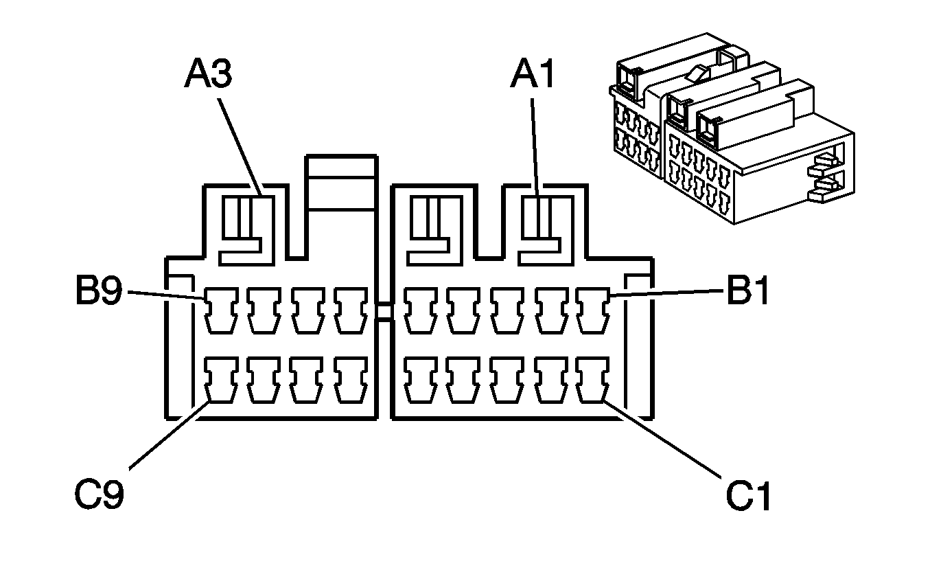
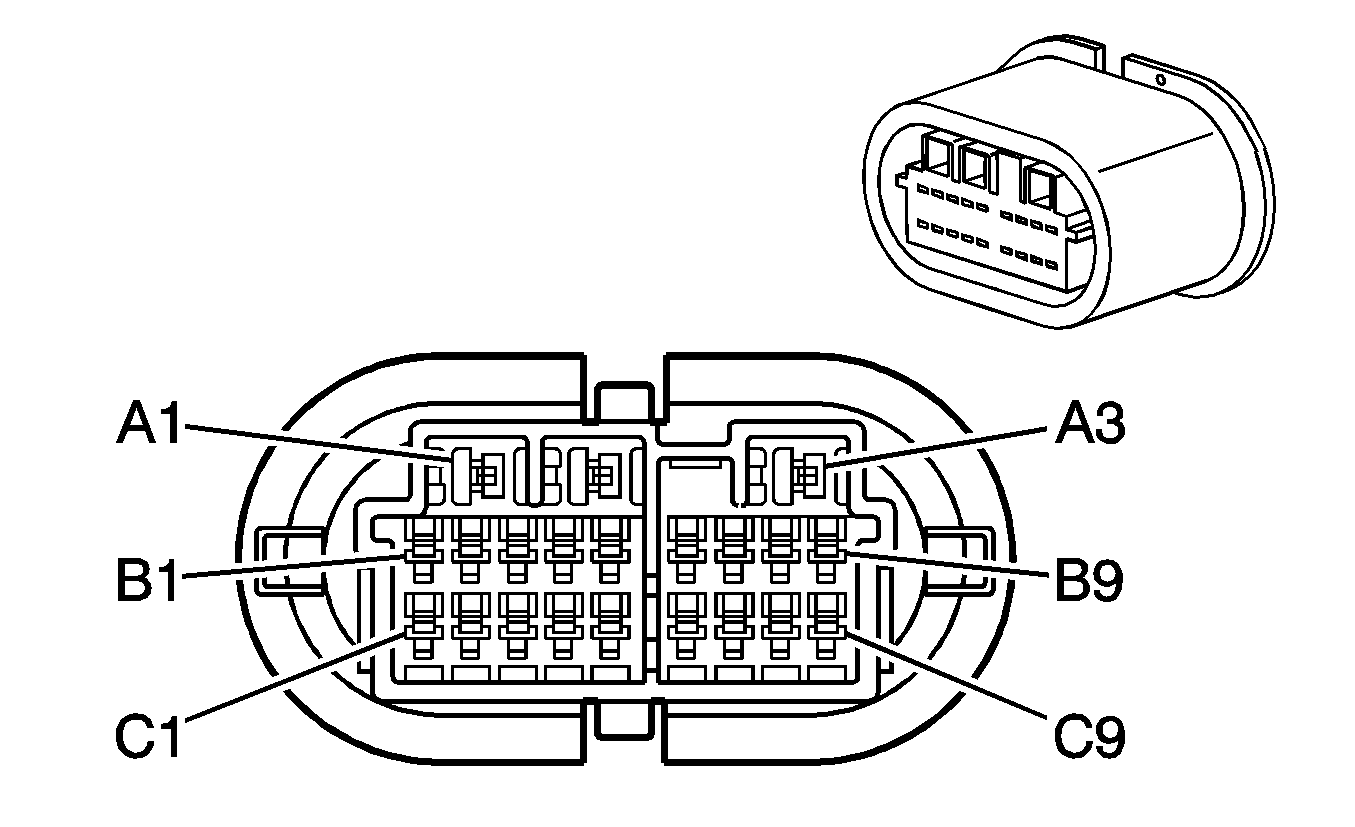
C700 - Body Harness to the LR Door Harness
|
|
Connector Part Information
| Connector Part Information
|
Pin | Wire Color | Circuit No. | Function | Pin | Wire Color | Circuit No. | Function |
|---|---|---|---|---|---|---|---|
A1 | D-GN | 168 | Power Window Master Switch Left Rear Up Signal | A1 | D-GN | 168 | Power Window Master Switch Left Rear Up Signal |
A2 | PU | 169 | Power Window Master Switch Left Rear Down Signal | A2 | PU | 169 | Power Window Master Switch Left Rear Down Signal |
A3 | D-BU | 1307 | Power Window Master Switch Lockout Control | A3 | D-BU | 1307 | Power Window Master Switch Lockout Control |
B1-B4 | -- | -- | Not Used | B1-B4 | -- | -- | Not Used |
B5 | TN/WH | 746 | Passenger Door Ajar Switch Signal | B5 | RD/BK | 746 | Passenger Door Ajar Switch Signal |
B6 | -- | -- | Not Used | B6 | BK | 746 | Not Used |
B7 | -- | -- | Not Used | B7 | -- | -- | Not Used |
B8 | GY | 295 | Door Lock Actuator Lock Control | B8 | GY | 295 | Door Lock Actuator Lock Control |
B9 | -- | -- | Not Used | B9 | -- | -- | Not Used |
C1 | -- | -- | Not Used | C1 | -- | -- | Not Used |
C2 | YE | 116 | Left Rear Speaker Output (-) | C2 | BN | 116 | Left Rear Speaker Output (-) |
C3 | BN | 199 | Left Rear Speaker Output (+) | C3 | YE | 199 | Left Rear Speaker Output (+) |
C4 | -- | -- | Not Used | C4 | -- | -- | Not Used |
C5 | PU | 294 | Not Used | C5 | PU | 294 | Not Used |
C6 | BK | 750 | Ground | C6 | BK | 750 | Ground |
C7 | -- | -- | Not Used | C7 | -- | -- | Not Used |
C8 | TN | 294 | Door Lock Actuator Unlock Control | C8 | TN | 294 | Door Lock Actuator Unlock Control |
C9 | -- | -- | Not Used | C9 | -- | -- | Not Used |
C800 - Body Harness to the RR Door Harness

|

|
Connector Part Information
| Connector Part Information
|
Pin | Wire Color | Circuit No. | Function | Pin | Wire Color | Circuit No. | Function |
|---|---|---|---|---|---|---|---|
A1 | L-GN | 170 | Power Window Master Switch Right Rear Up Signal | A1 | D-GN | 170 | Power Window Master Switch Right Rear Up Signal |
A2 | PU | 171 | Power Window Master Switch Right Rear Down Signal | A2 | PU | 171 | Power Window Master Switch Right Rear Down Signal |
A3 | D-BU | 1307 | Power Window Master Switch Lockout Control | A3 | D-BU | 1307 | Power Window Master Switch Lockout Control |
B1-B4 | -- | -- | Not Used | B1-B4 | -- | -- | Not Used |
B5 | -- | -- | Not Used | B5 | RD/BK | 746 | Not Used |
B6 | TN/WH | 746 | Passenger Door Ajar Switch Signal | B6 | BK | 746 | Passenger Door Ajar Switch Signal |
B7 | -- | -- | Not Used | B7 | -- | -- | Not Used |
B8 | BK | 850 | Ground | B8 | GY | 850 | Ground |
B9 | -- | -- | Not Used | B9 | -- | -- | Not Used |
C1 | -- | -- | Not Used | C1 | -- | -- | Not Used |
C2 | L-BU | 115 | Right Rear Speaker Output (-) | C2 | BN | 115 | Right Rear Speaker Output (-) |
C3 | D-BU | 46 | Right Rear Speaker Output (+) | C3 | YE | 46 | Right Rear Speaker Output (+) |
C4 | -- | -- | Not Used | C4 | -- | -- | Not Used |
C5 | TN | 294 | Door Lock Actuator Unlock Control | C5 | PU | 294 | Door Lock Actuator Unlock Control |
C6 | GY | 295 | Door Lock Actuator Lock Control | C6 | BK | 295 | Door Lock Actuator Lock Control |
C7 | -- | -- | Not Used | C7 | -- | -- | Not Used |
C8 | -- | -- | Not Used | C8 | TN | 294 | Not Used |
C9 | -- | -- | Not Used | C9 | -- | -- | Not Used |
C900 - Liftgate Jumper Harness to the Liftgate Harness

|

|
Connector Part Information
| Connector Part Information
|
Pin | Wire Color | Circuit No. | Function | Pin | Wire Color | Circuit No. | Function |
|---|---|---|---|---|---|---|---|
A | BN | 9 | Park Lamp Supply Voltage | A | BN | 9 | Park Lamp Supply Voltage |
B | GY | 295 | Door Lock Actuator Lock Control | B | GY | 295 | Door Lock Actuator Lock Control |
C | YE | 143 | Accessory Voltage | C | YE | 143 | Accessory Voltage |
D | WH | 393 | Rear Window Wiper Motor Control | D | WH | 393 | Rear Window Wiper Motor Control |
E | TN | 294 | Door Lock Actuator Unlock Control | E | TN | 294 | Door Lock Actuator Unlock Control |
F | OG/BK | 744 | Rear Compartment Lid Ajar Switch | F | OG/BK | 744 | Rear Compartment Lid Ajar Switch |
C901 - Liftgate Jumper Harness to the Liftgate Harness

|

|
Connector Part Information
| Connector Part Information
|
Pin | Wire Color | Circuit No. | Function | Pin | Wire Color | Circuit No. | Function |
|---|---|---|---|---|---|---|---|
1 | PU | 293 | Rear Defogger Element Supply Voltage | 1 | PU | 293 | Rear Defogger Element Supply Voltage |
2 | BK | 750 | Ground | 2 | BK | 750 | Ground |
C902 - Left License Lamp to the Liftgate Harness

|

|
Connector Part Information
| Connector Part Information
|
Pin | Wire Color | Circuit No. | Function | Pin | Wire Color | Circuit No. | Function |
|---|---|---|---|---|---|---|---|
1 | BN | 9 | Park Lamp Supply Voltage | 1 | BN | 9 | Park Lamp Supply Voltage |
2 | BK | 750 | Ground | 2 | BK | 750 | Ground |
C903 - Right License Lamp to the Liftgate Harness

|

|
Connector Part Information
| Connector Part Information
|
Pin | Wire Color | Circuit No. | Function | Pin | Wire Color | Circuit No. | Function |
|---|---|---|---|---|---|---|---|
1 | BN | 9 | Park Lamp Supply Voltage | 1 | BN | 9 | Park Lamp Supply Voltage |
2 | BK | 750 | Ground | 2 | BK | 750 | Ground |
C904 - CHMSL Jumper Harness to the CHMSL Harness

|

|
Connector Part Information
| Connector Part Information
|
Pin | Wire Color | Circuit No. | Function | Pin | Wire Color | Circuit No. | Function |
|---|---|---|---|---|---|---|---|
1 | L-BU | 20 | Stop Lamp Switch Signal | 1 | L-BU | 20 | Stop Lamp Switch Signal |
2 | BK | 850 | Ground | 2 | BK | 850 | Ground |
