Special Tools
| • | J-08614-A Pinion Flange Holder and Remover |
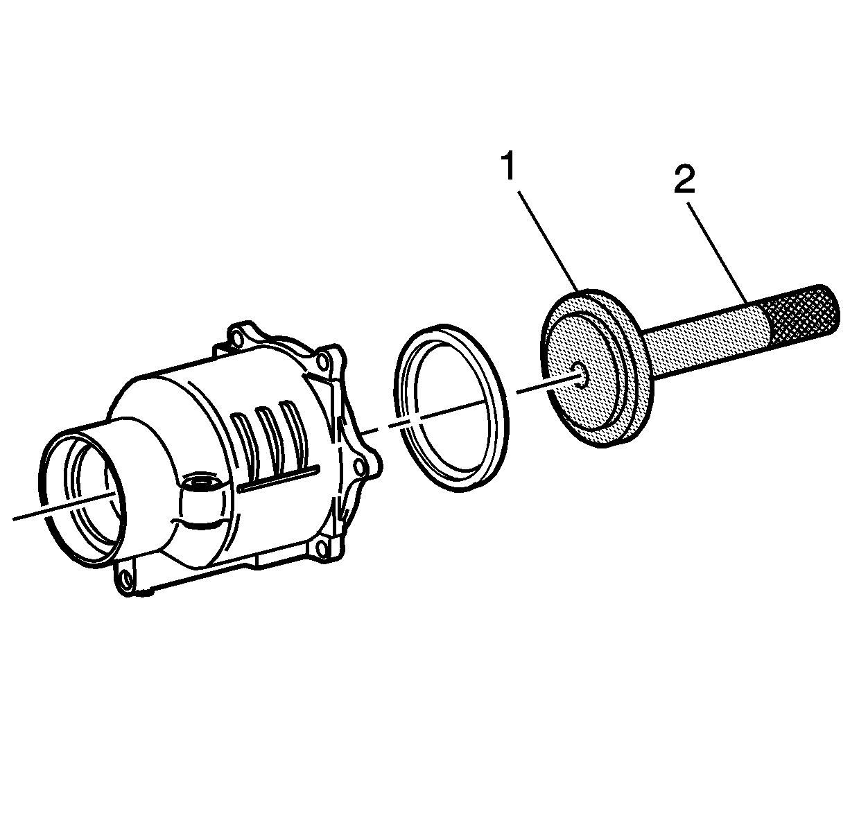
| • | J 8092 Driver Handle |
| • | J 46607 Alignment Tool |
| • | J 44852 Front Clutch Drum Seal Installer |
| • | J 44853 Rear Clutch Drum Seal Installer |
Removal Procedure
- Raise and support the vehicle. Refer to Lifting and Jacking the Vehicle .
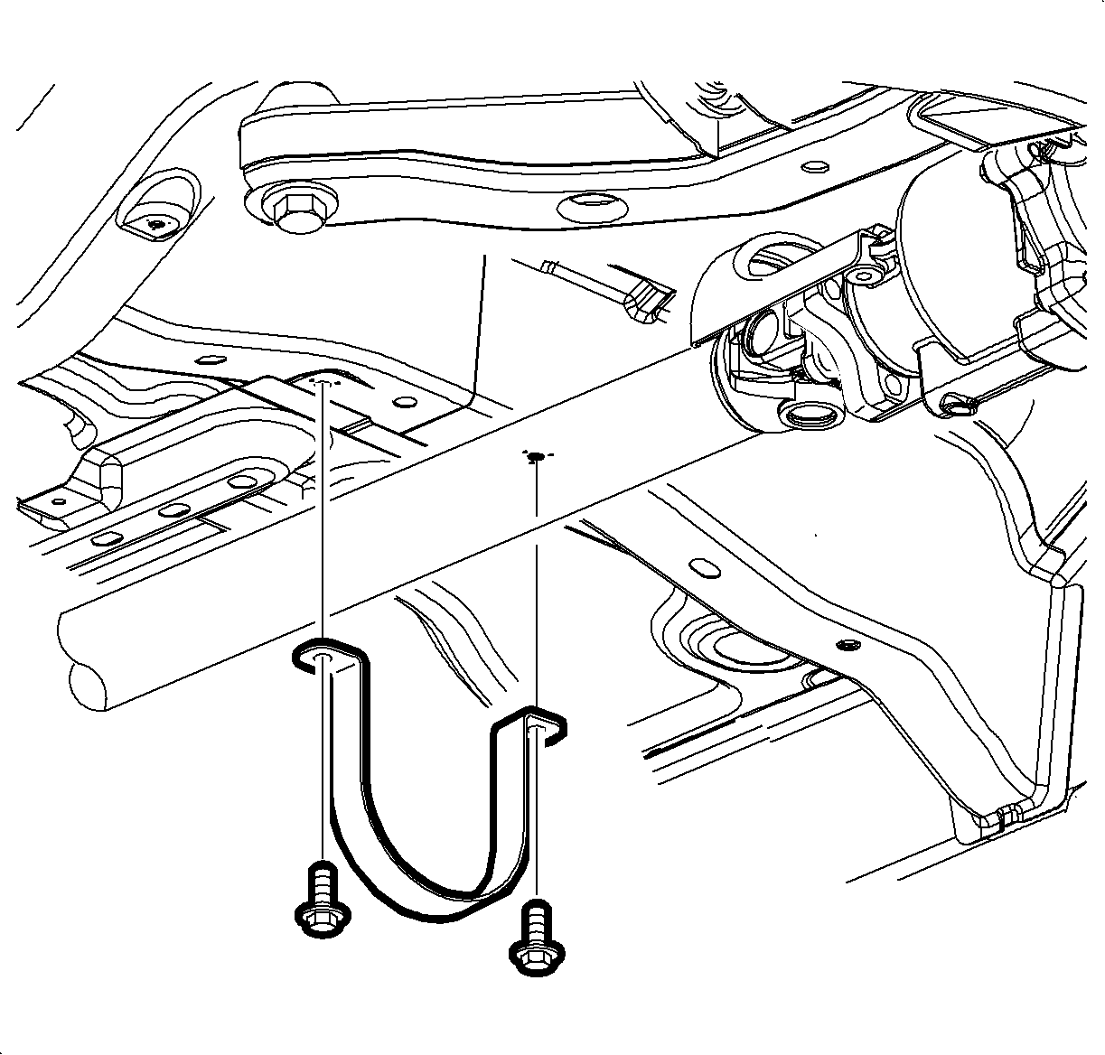
- Remove the propeller shaft underbody guard loop bolts.
- Remove the guard loop.
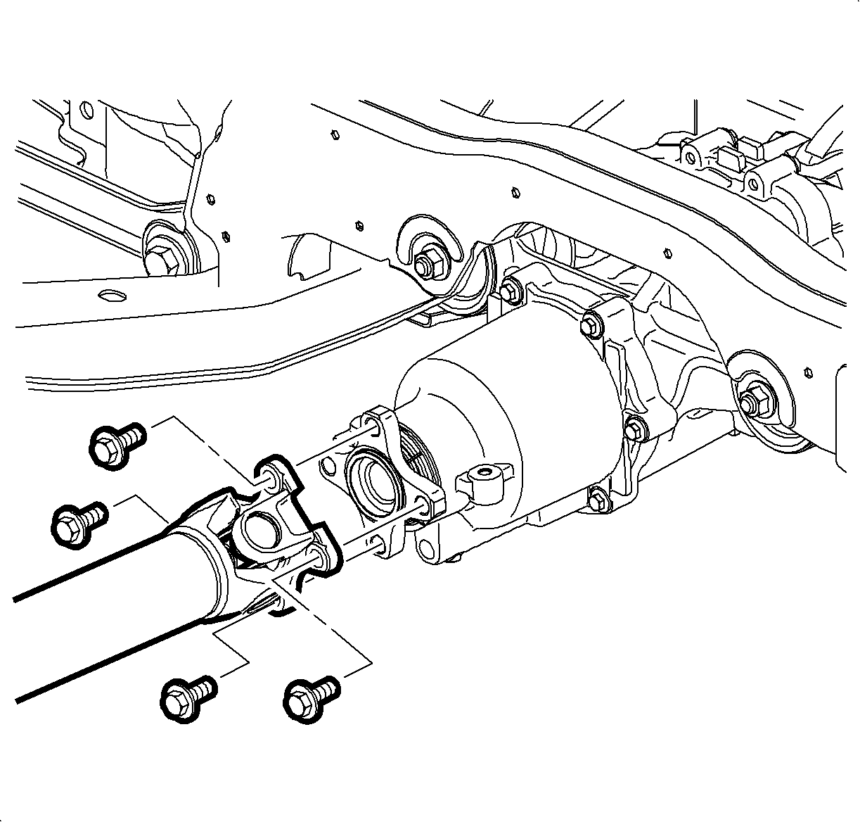
- Reference mark the propeller shaft flange-to-pinion flange relationship at the rear drive module (RDM).
- Remove the propeller shaft flange mounting bolts at the RDM pinion flange.
- Position the end of the propeller shaft away from the RDM and secure with heavy mechanics wire, or equivalent.
- Place a container under the RDM housing.
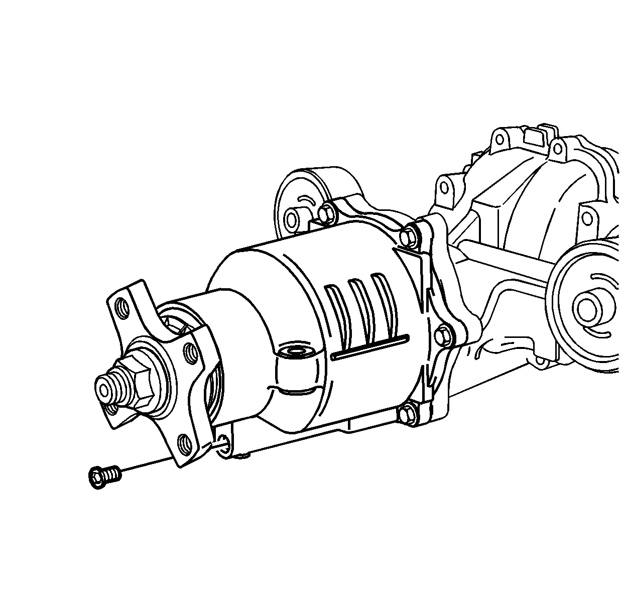
- Remove the RDM drain plug.
- Drain the RDM fluid.
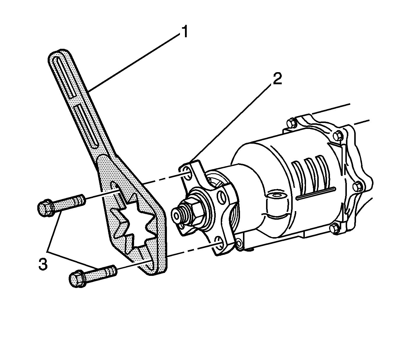
- Install the J-08614-A (1) to the pinion flange (2) using M10x1.50x30 bolts.
- Hold J-08614-A and use a breaker bar and 27 mm (1 1/16 in) socket.
- Loosen the pinion flange nut.
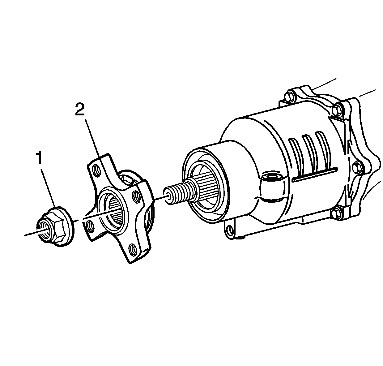
- Remove and discard the pinion flange nut (1).
- Remove the pinion flange (2).
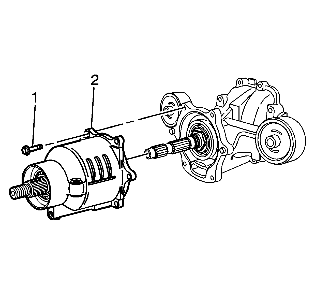
- Remove the RDM housing cover bolts (1).
- Carefully remove the housing cover (2) from the RDM.
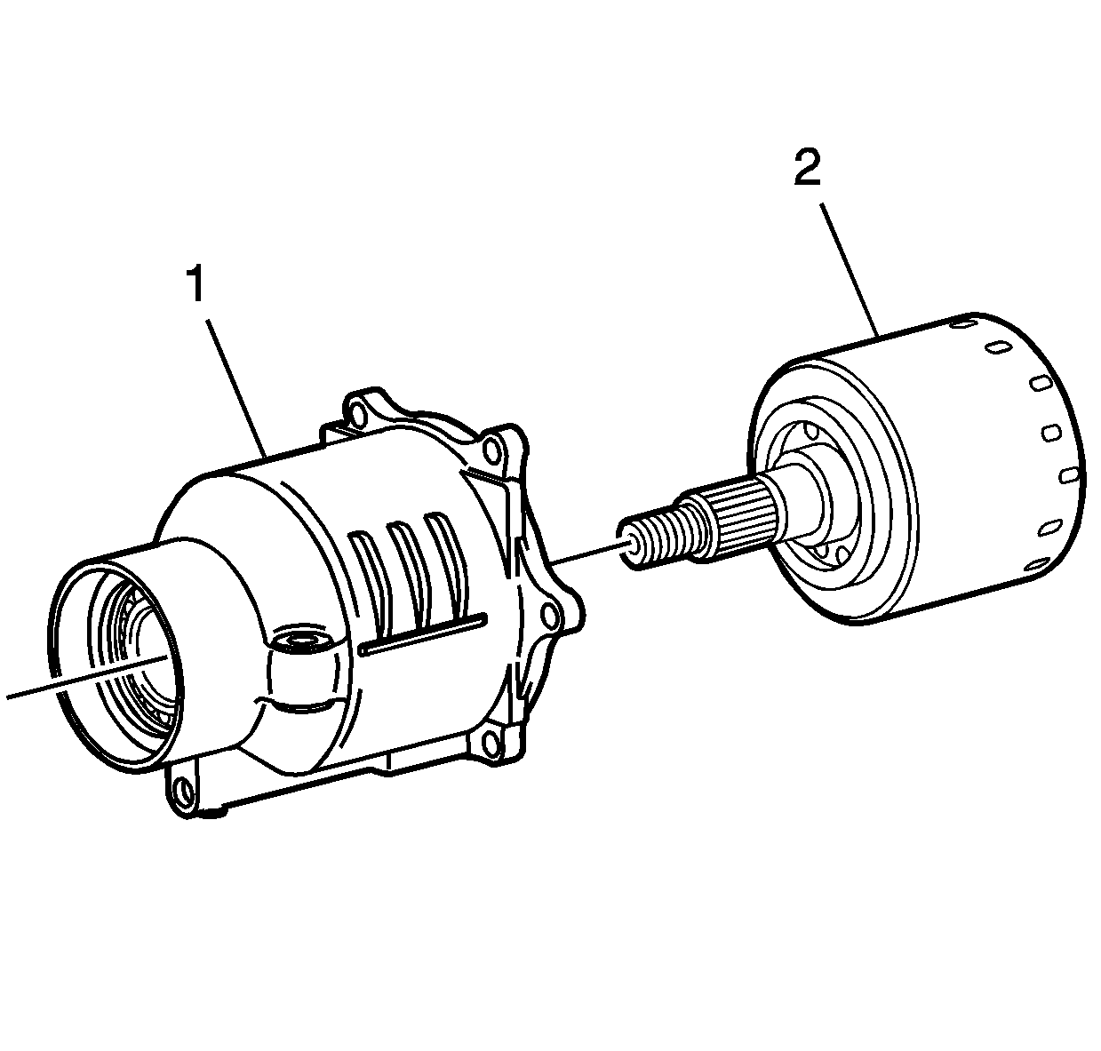
- Remove the clutch drum (2) from the housing cover (1).
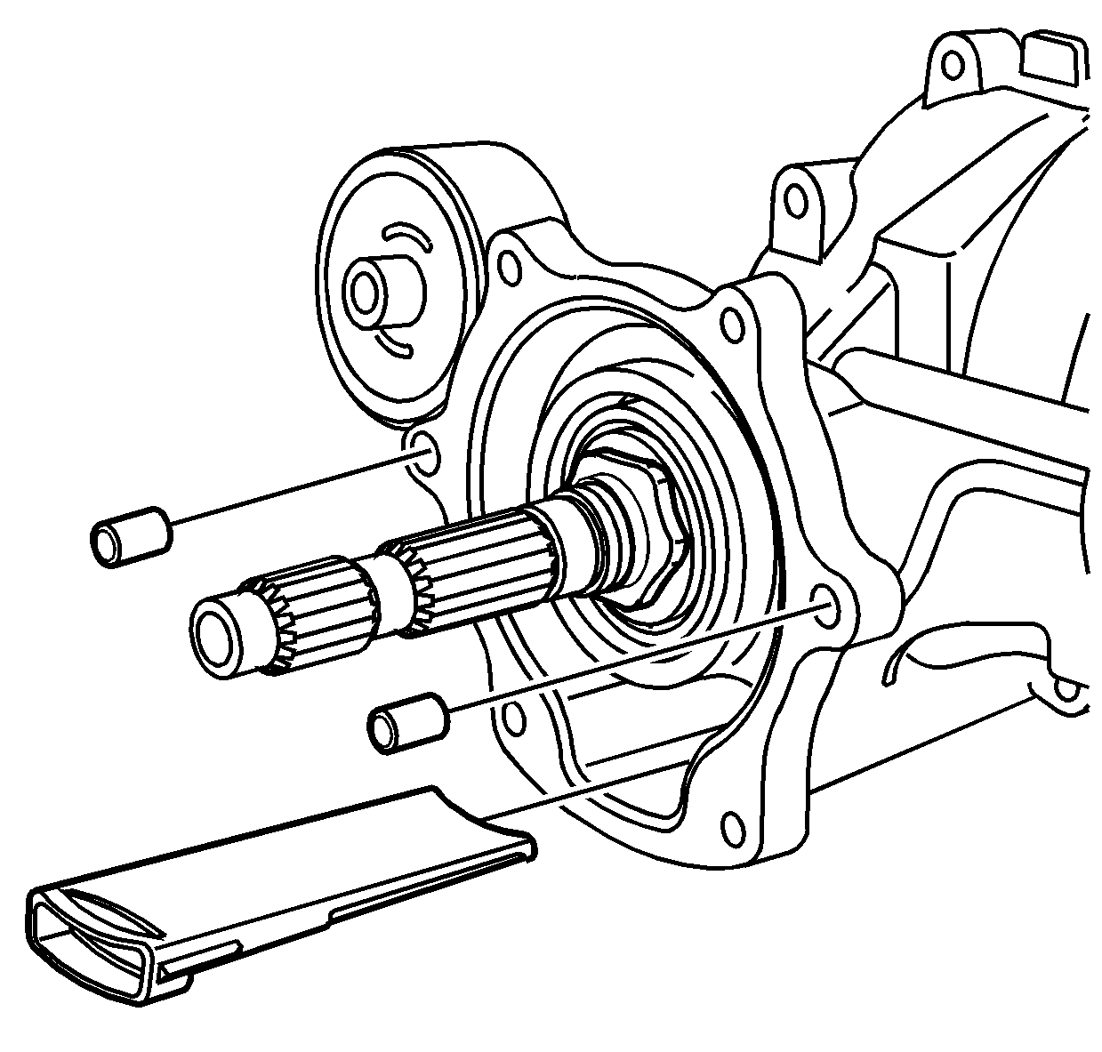
- Remove the filter assembly.
- Remove the locating pins.
- Remove all traces of sealer from the housing cover and RDM sealing surfaces.
- Clean the housing cover and RDM sealing surfaces with denatured alcohol or equivalent, and dry with a clean, lint-free cloth.
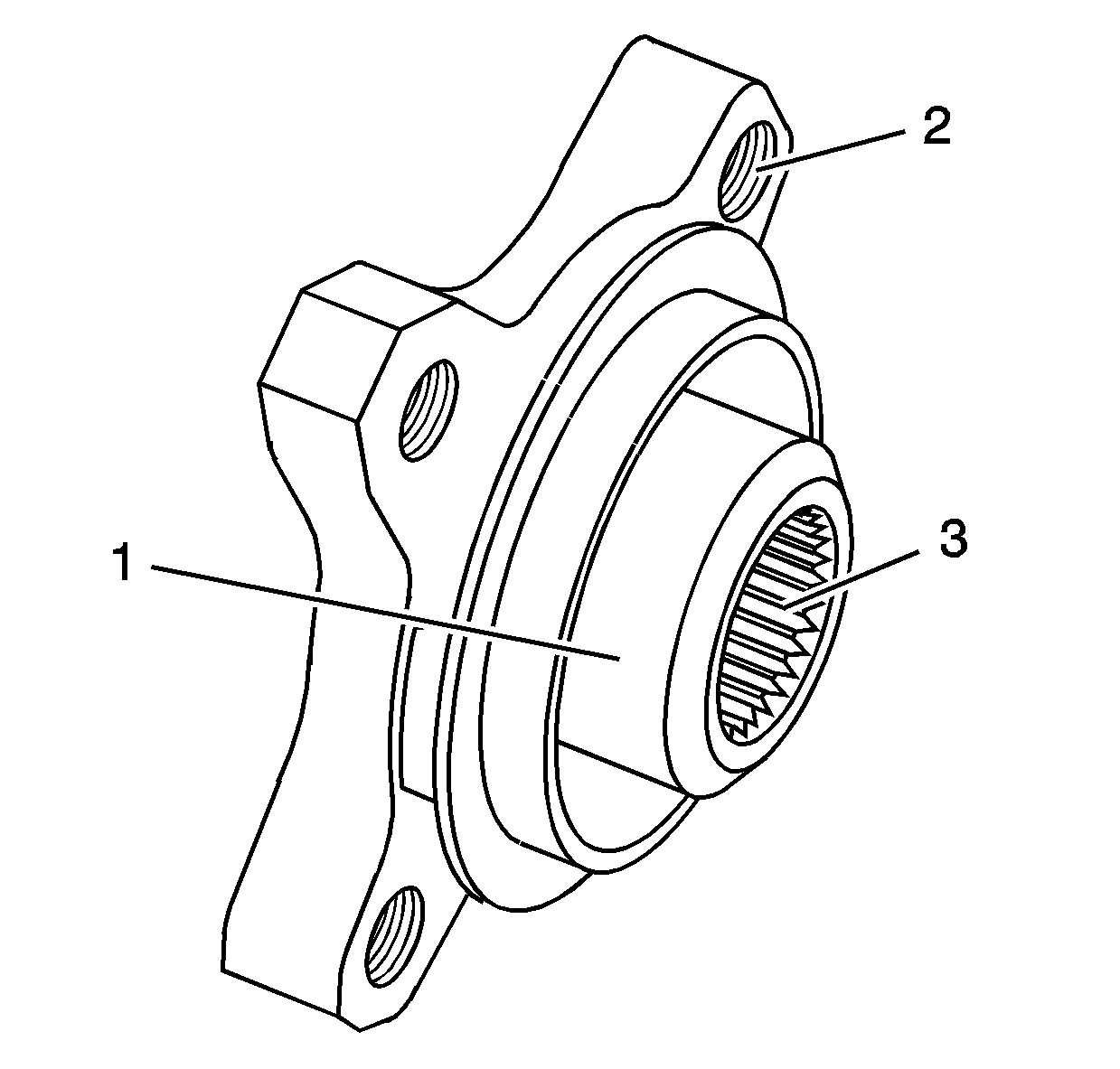
- Check the pinion flange sealing surface (1) for wear or gouges, the bolt threads (2) for damage and the pinion splines (3) for worn or damaged splines.
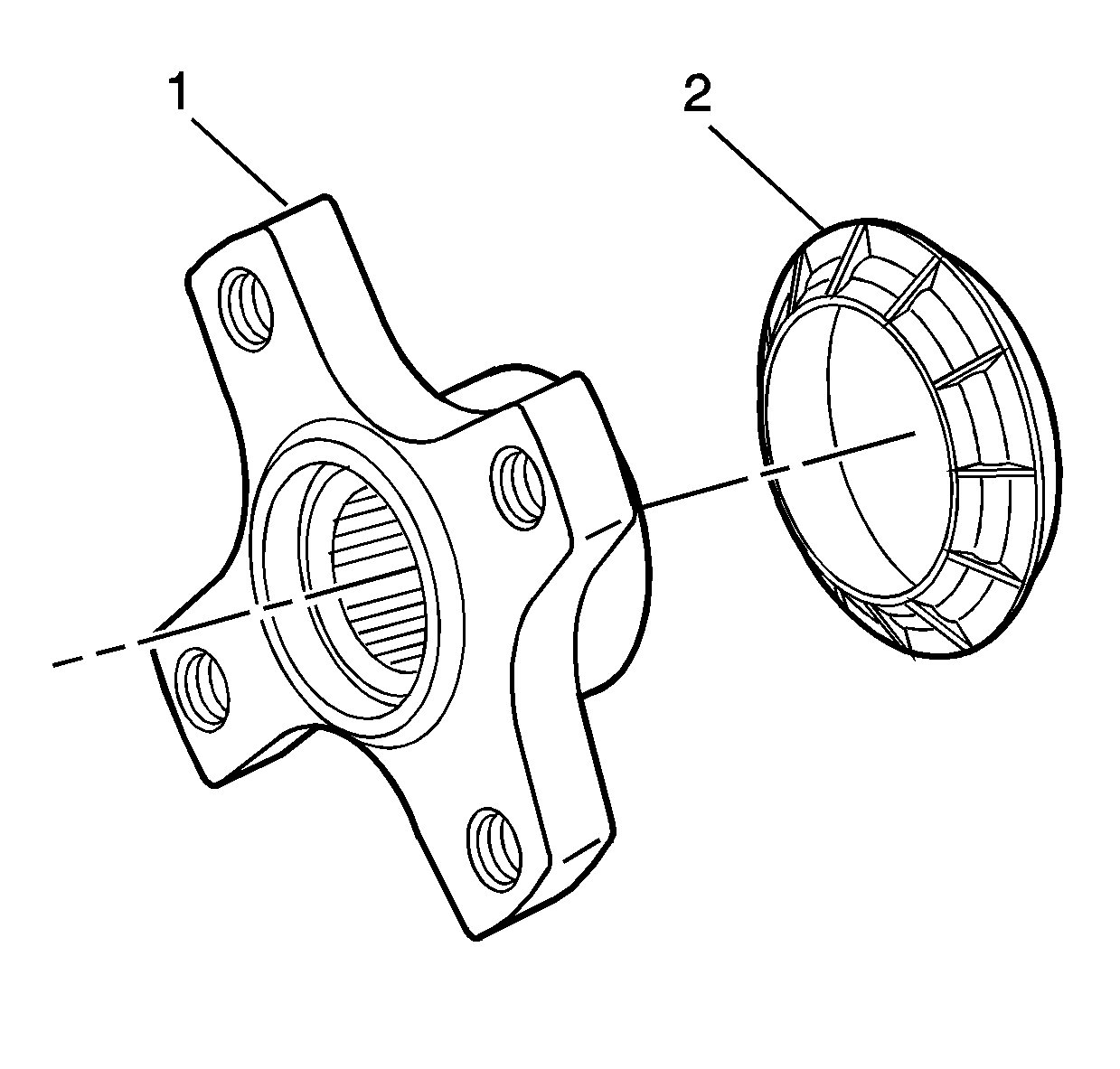
- Inspect the dust deflector (2) for cracks .
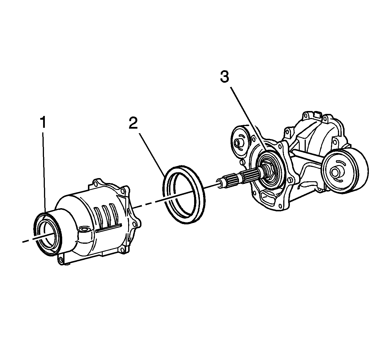
- Inspect the pinion flange seal (1), the front seal (2) and the rear seal (3) for tears, cuts, and gouges on the seals and sealing surfaces.
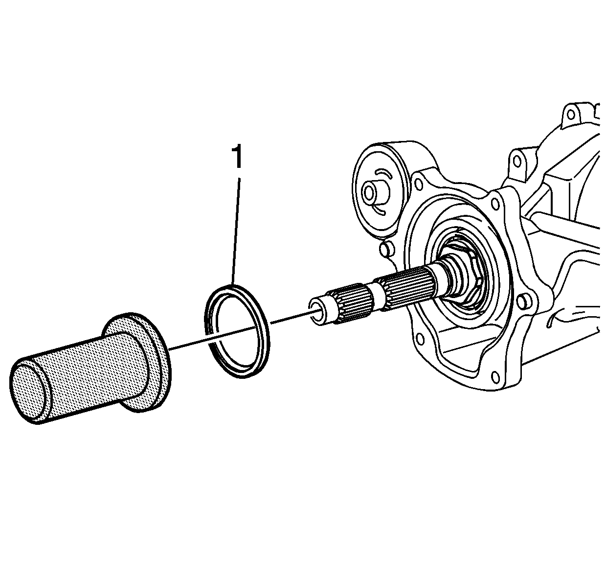
- If the rear seal (1) is damaged, replace using J 44853 . Install the clutch drum rear oil seal (1) to the differential housing.
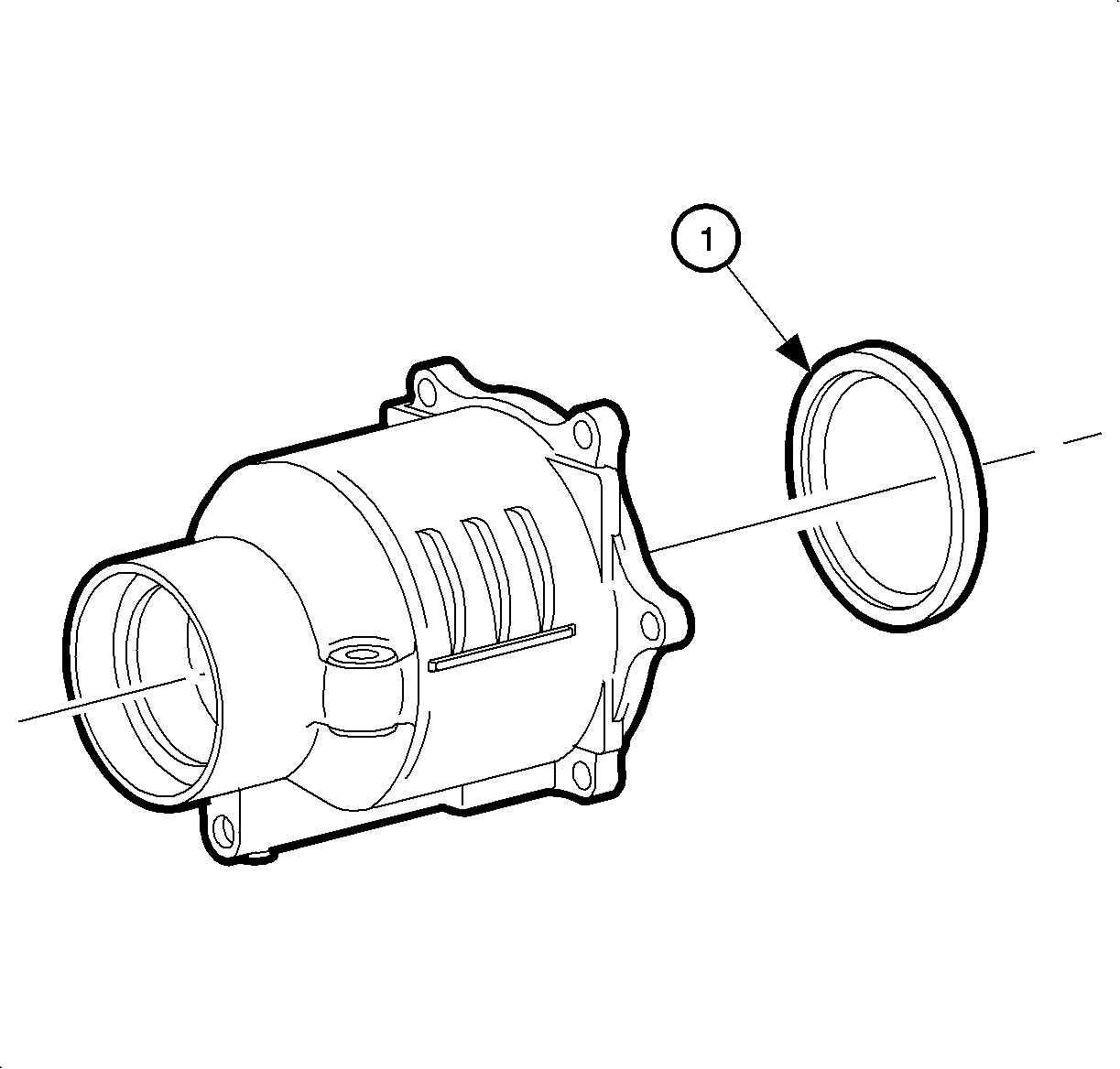
- Inspect the clutch cover oil seal (1). It is recessed into the clutch cover. Inspect for tears, cuts, and gouges on the seals and sealant surfaces.
- If the front seal is damaged, replace using J 44852 (1) and J 8092 (2). Install the front oil seal into the clutch cover.
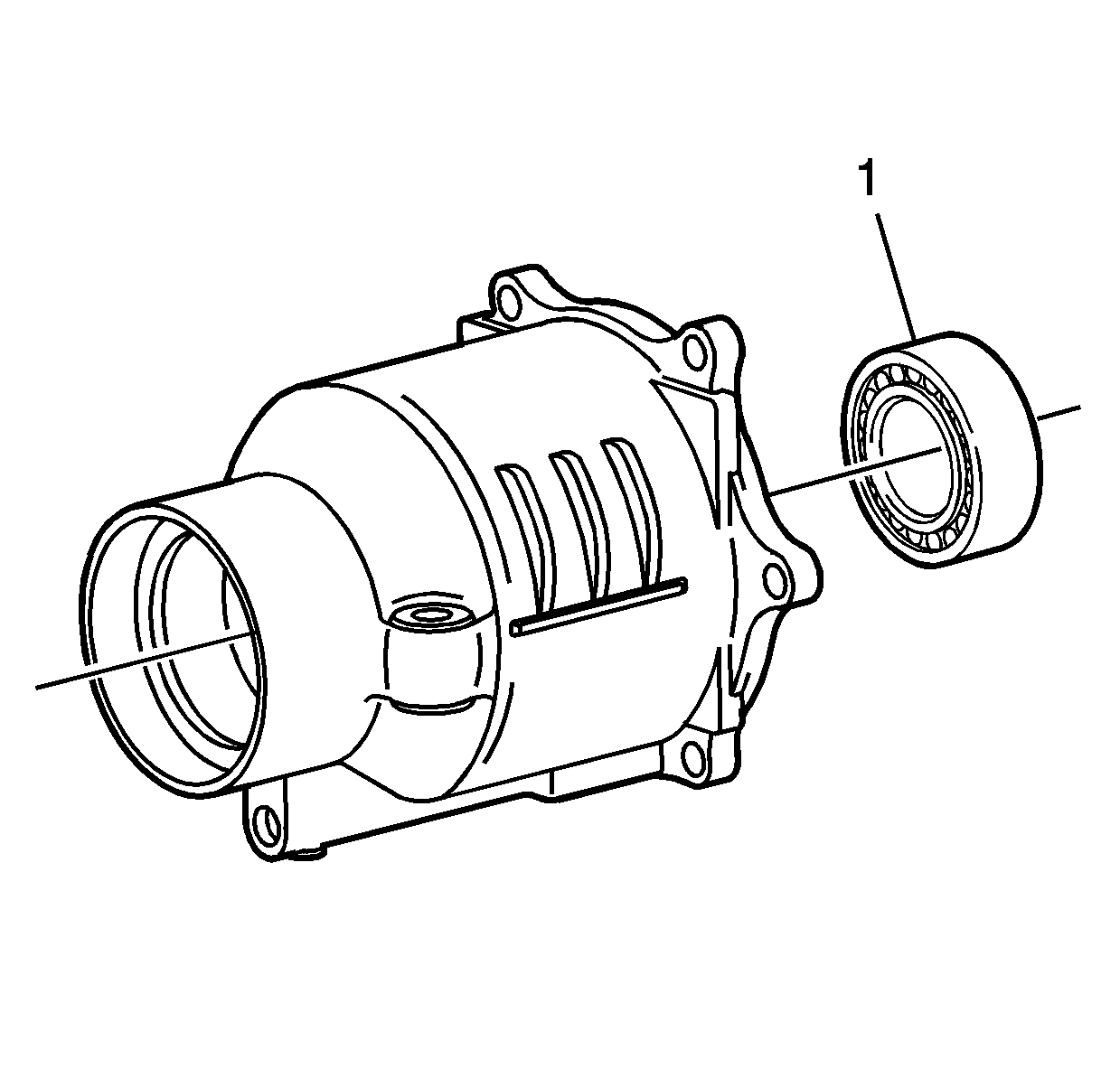
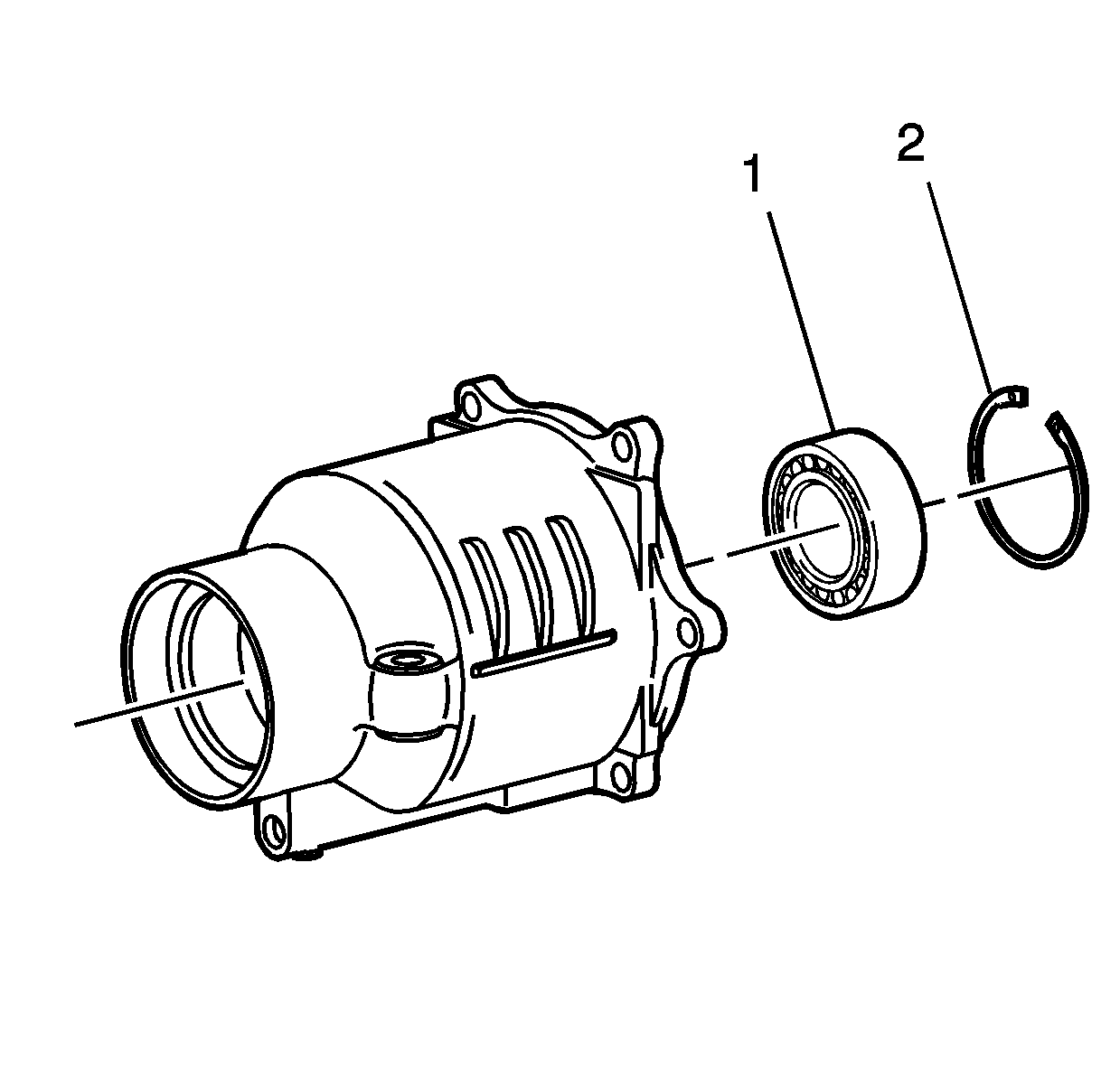
- Inspect the clutch cover bearing (1) for roughness and excessive play. It is recessed into the clutch cover.
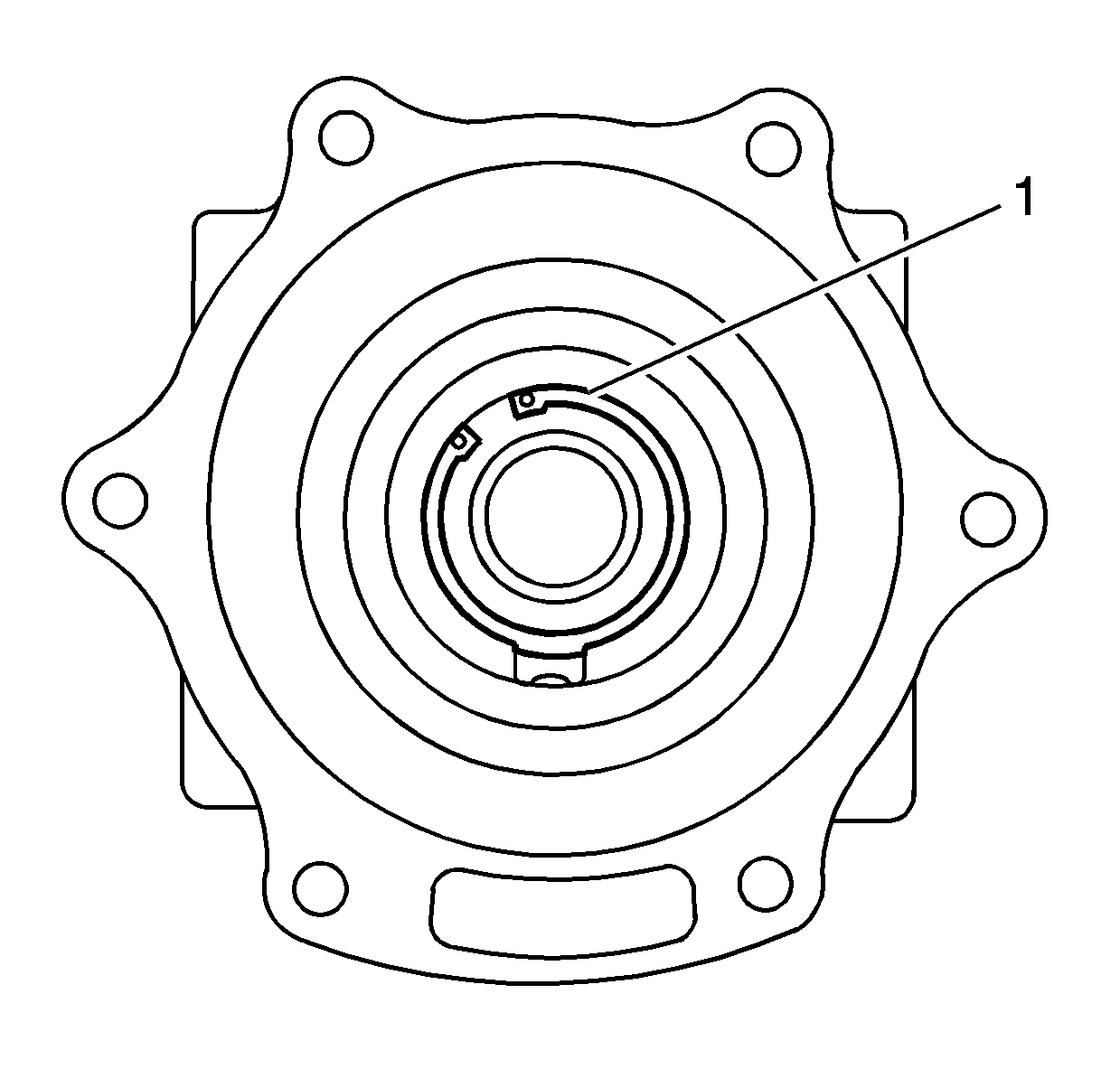
- Remove the snap ring (1).
- Drive the bearing (1) out from the inner race.
- Install the bearing (1) into the clutch over from the outer race with a suitable driver.
- Install the snap ring (2) into the groove.
Important: Do not gouge the housing cover and RDM sealing surfaces.
Important: The bearing must be replaced, if removed.

Installation Procedure
- Install a new filter assembly.
- Install the locating pins.
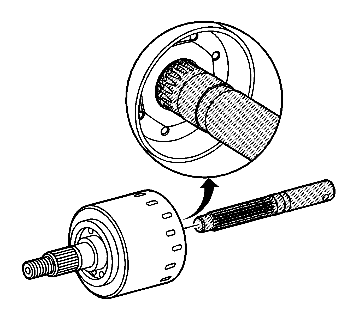
- Align the clutch with the pump and pump bushing. Place the J 46607 in the splines of the clutch. Twist alignment tool back and forth to align the pump and bushing. With a properly aligned clutch, the groove on the J 46607 will be flush with the drum as shown. Remove the tool by pulling straight out.
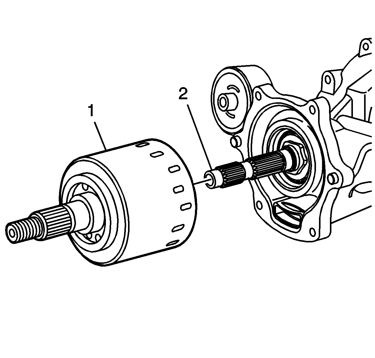
- Install the clutch drum (1) to the pinion shaft (2) .
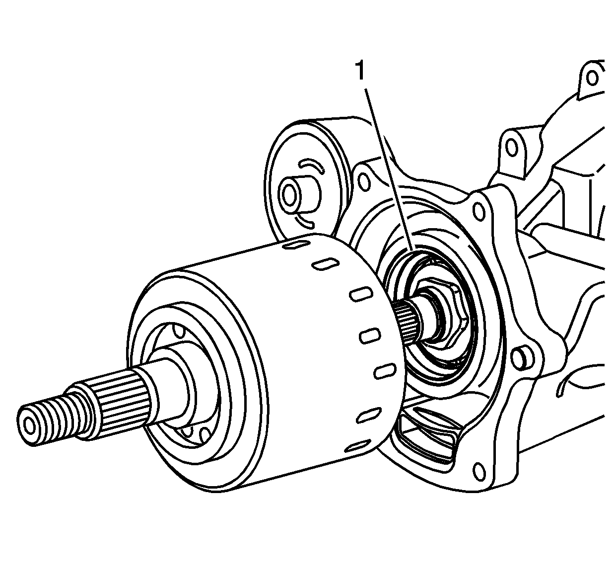
- When properly engaged, the clutch drum will be fully seated against the clutch drum oil seal (1).
- Apply a continuous bead of sealer, GM P/N 12346286 (Canadian P/N 10953472) of equal height and width to the RDM housing sealing surface.
- Install the clutch housing cover (1) to the RDM.
- Hand install the clutch housing cover bolts (2).
- Install the dust deflector (2) to the input flange (1) if removed.
- Install the input flange (2) to the clutch shaft.
- Hand install a new input flange nut (1) to the clutch shaft.
- Install the J-08614-A (1) to the pinion flange (2) using M10x1.50x30 bolts.
- Tighten the pinion nut.
- Thoroughly clean the drain plug threads and apply thread sealer, GM P/N 12346004 (Canadian P/N 10953480), to the plug threads.
- Install the RDM drain plug.
- Remove the RDM fill plug.
- Thoroughly clean the fill plug threads and apply thread sealer, GM P/N 12346004 (Canadian P/N 10953480), to the plug threads.
- Fill the RDM with lubricant. Refer to Rear Axle Lubricant Replacement .
- Install the fill plug.
- Thoroughly clean and apply threadlocker, GM P/N 89021297 (Canadian P/N 10953488) to the propeller shaft flange mounting bolt threads.
- Align the reference marks on the propeller shaft flange and the RDM input flange.
- Install the propeller shaft flange mounting bolts.
- Install the propeller shaft underbody guard loop.
- Install the propeller shaft underbody guard loop bolts.
- Lower the vehicle.

Notice: Do not submerge the clutch drum in solvent. This will damage friction material and geroter pump.
Important: The clutch drum may require some slight rotational movement to install completely. If the clutch is not fully seated, the clutch housing may break when tightening bolts.
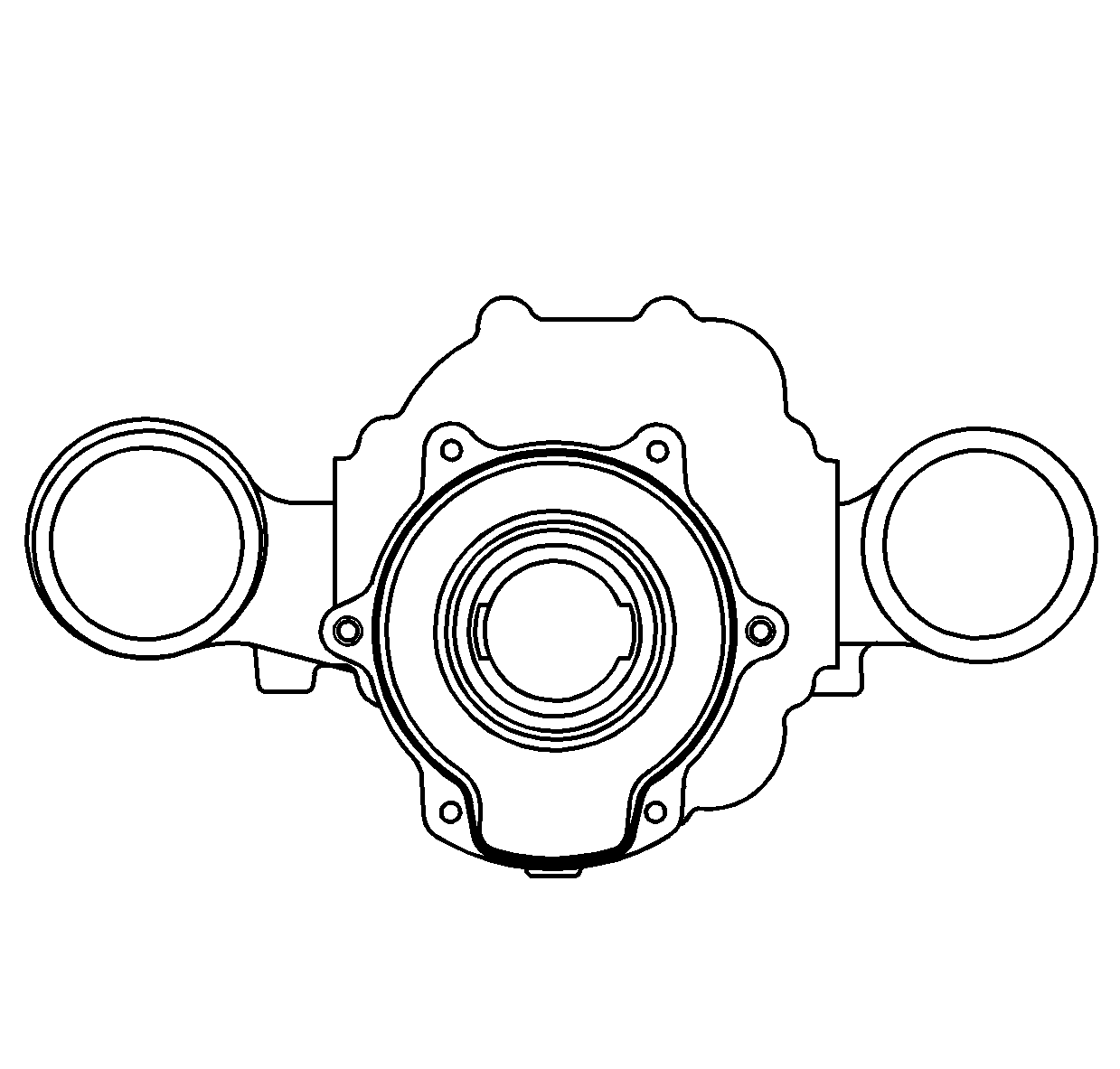
Specification
Apply sealer to a height and width of 2.5 mm (0.098 in).
Notice: The clutch cover housing must be fully seated to the rear drive module (RDM). Do Not use the mounting bolts to draw the cover to the RDM. If the cover does not fully seat to the RDM, the clutch drum assembly splines must be realigned to the pinion shaft splines before proceeding. Failure to follow these instructions will result in damage to the clutch assembly.
Important: Do not disturb the sealer bead applied to the RDM sealing surface.
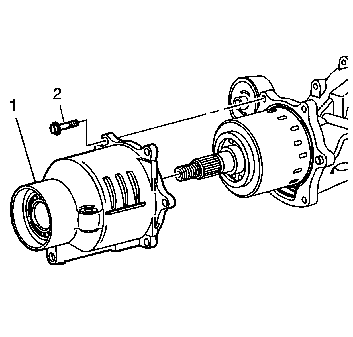
Notice: Refer to Fastener Notice in the Preface section.
Tighten
Tighten the bolts to 26 N·m (19 lb ft).


Tighten
Tighten the nut to 203 N·m (150 lb ft).

Tighten
Tighten the plug to 30 N·m (22 lb ft).
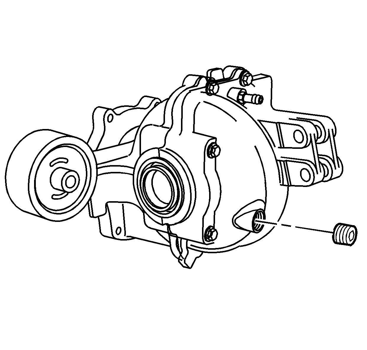
Tighten
Tighten the plug to 35 N·m (26 lb ft).

Tighten
Tighten the bolts to 50 N·m (37 lb ft).

Tighten
Tighten the bolts to 24 N·m (18 lb ft).
