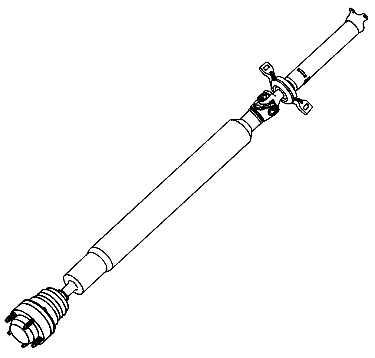
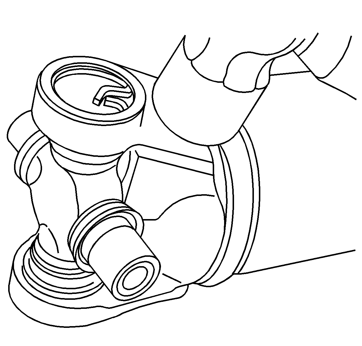
Tool Required
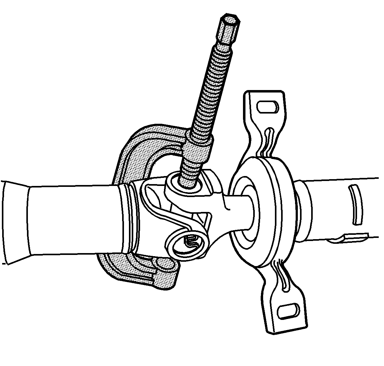
J 45270 Universal Joint Remover/Installer
- Remove the propeller shaft.
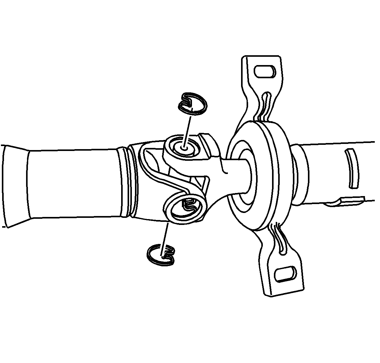
- Remove the snap rings.
- Use J 45270 to remove the U-joint caps.
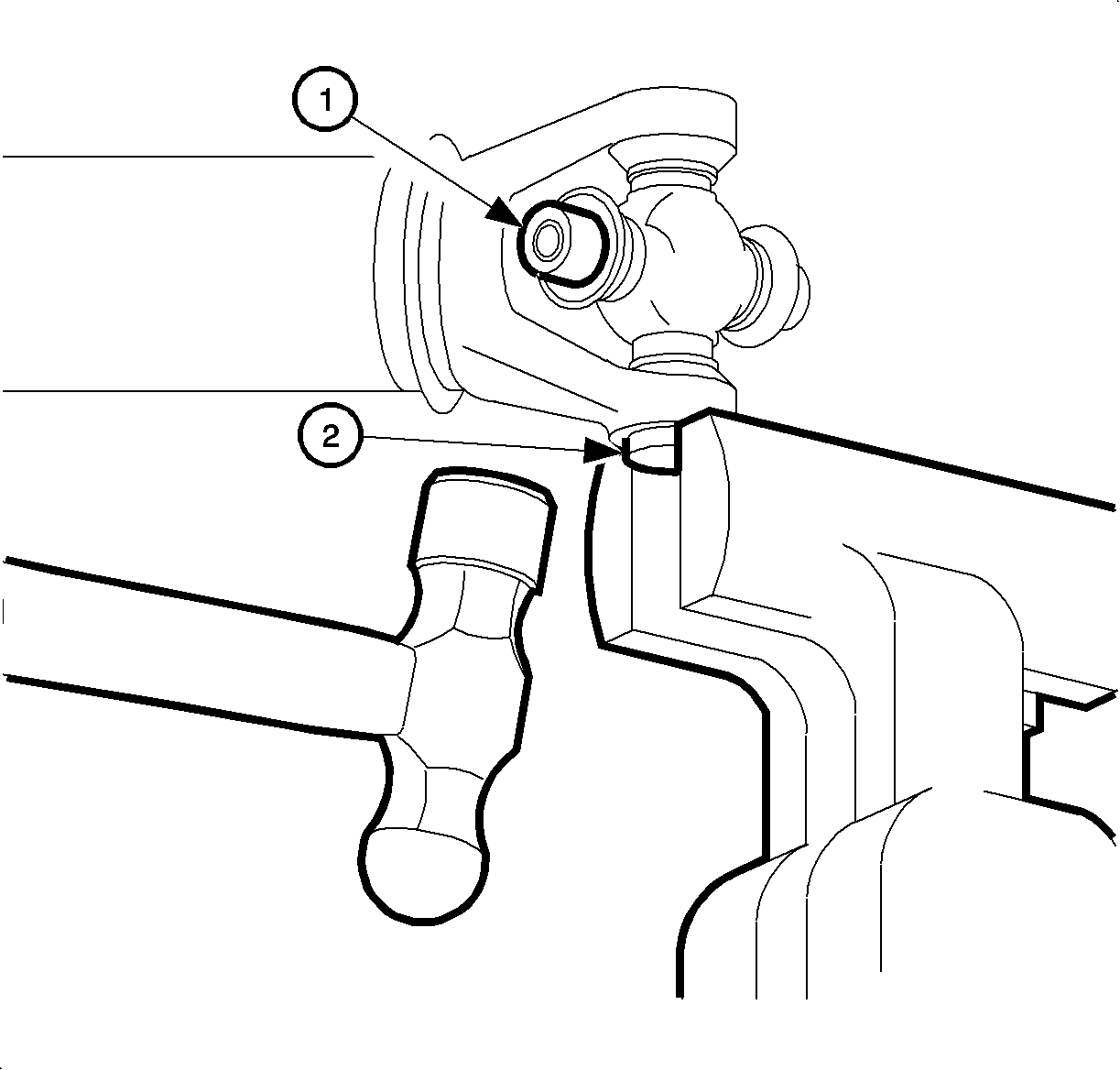
- If the bearing cup is not completely removed (2), place the exposed portion of the bearing cap into a soft-jaw vise. Tap upwards on the propeller shaft yoke with a hammer until the bearing cap is free of the propeller shaft yoke.
- Rotate the propeller shaft and press the opposite bearing cup out of the yoke.
- Remove the cross from the yoke.
- Remove the remaining universal joint parts from the yoke.
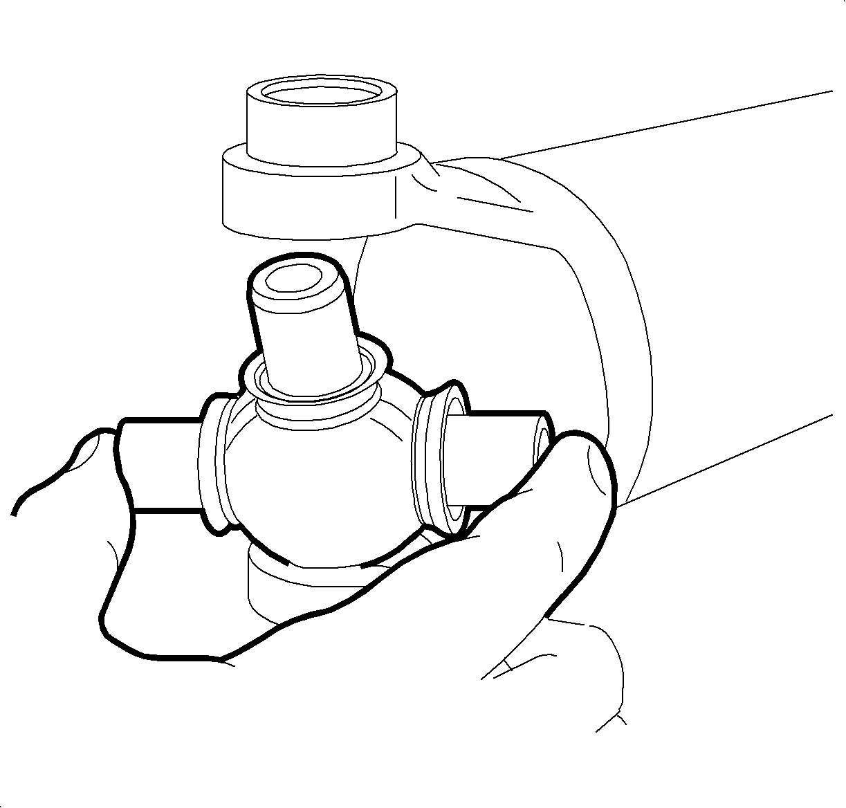
- Inspect the retaining ring grooves for the following:
- Inspect the bearing cup bores for burns or imperfections.
- Clean the retaining ring grooves.
Notice: Never clamp propeller shaft tubing in a vise. Clamping propeller shaft tubing in a vise could dent or deform the tube, causing an imbalance or unsafe condition. Always clamp on one end of the yokes and support the shaft horizontally.
Important: Prior to disassembly, mark the positions of the driveshaft components relative to the driveshaft tube. All components must be reassembled in the same relationship to maintain proper balance.
| 2.1. | Pinch the ends of the snap ring together with a pair of pliers. |
| 2.2. | If a snap ring does not readily snap out of the groove in the yoke, tap the end of the bearing cup lightly in order to relieve pressure from ring. |
| • | Dirt |
| • | Corrosion |
| • | Pieces of the old ring |
Important: Corrosion or dirt may prevent bearing cup installation and may prohibit the proper seating of the bearing retainers.
Installation Procedure
- Remove the bearing cups from the new universal joint journals.
- Coat the needle bearings in the bearing cups with a thin layer of grease that is present on the journal. Use your finger to apply the grease.
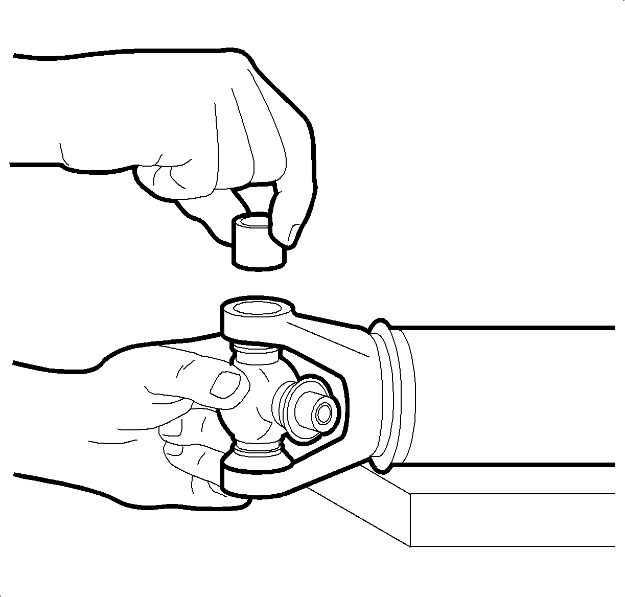
- Install one bearing cup partway into one side of the yoke.
- Turn the yoke ear toward the bottom.
- Install the cross into the yoke so that the trunnion seats freely into the bearing cup.
- With the trunnion seated in the bearing cup, press the bearing cup into the yoke until it is flush with the yoke ear.
- Install the opposite bearing cup partway into the yoke ear.
- Make sure that the trunnions are started straight and true into both bearing cups.
- Press the opposite bearing cup into the yoke ear.
- Install the bearing retainer in the retainer groove.
- After the clips are installed, check for binding.
- If cross binding is felt, it may be necessary to strike the flange area in order to remove excess pressure from the cross.

Important: If the bearing cup seems to bind or hang-up, stop pressing. Check the needle bearings for misalignment in the bearing cup.
| • | Work the cross all the time. |
| • | Check for free unbinding movement of the trunnions in the bearing cups. |
| • | Press the bearing cup into the yoke until the bearing retainer groove is visible over the top of the bearing cup. |
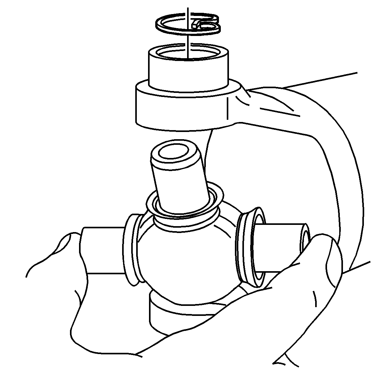
Important: Assemble the universal joint using the yellow snap rings supplied in the kit. If difficulty is encountered with the yellow snap rings, install the black snap rings supplied in the kit.
| • | Continue pressing until you can snap both retainers into place. |
| • | A small amount of chassis grease may help the snap ring seat in the bearing cup groove. |
