For 1990-2009 cars only
Removal Procedure
Tools Required
| • | J 22912-B Split-Plate Bearing Puller |
| • | J 45270 Universal Joint Remover/Installer |
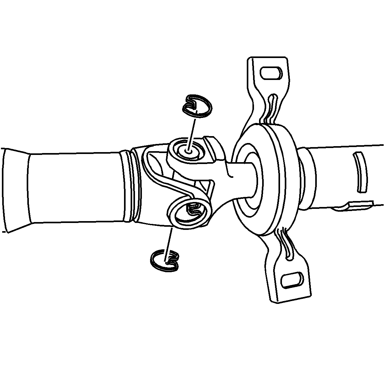
- Remove the snap rings.
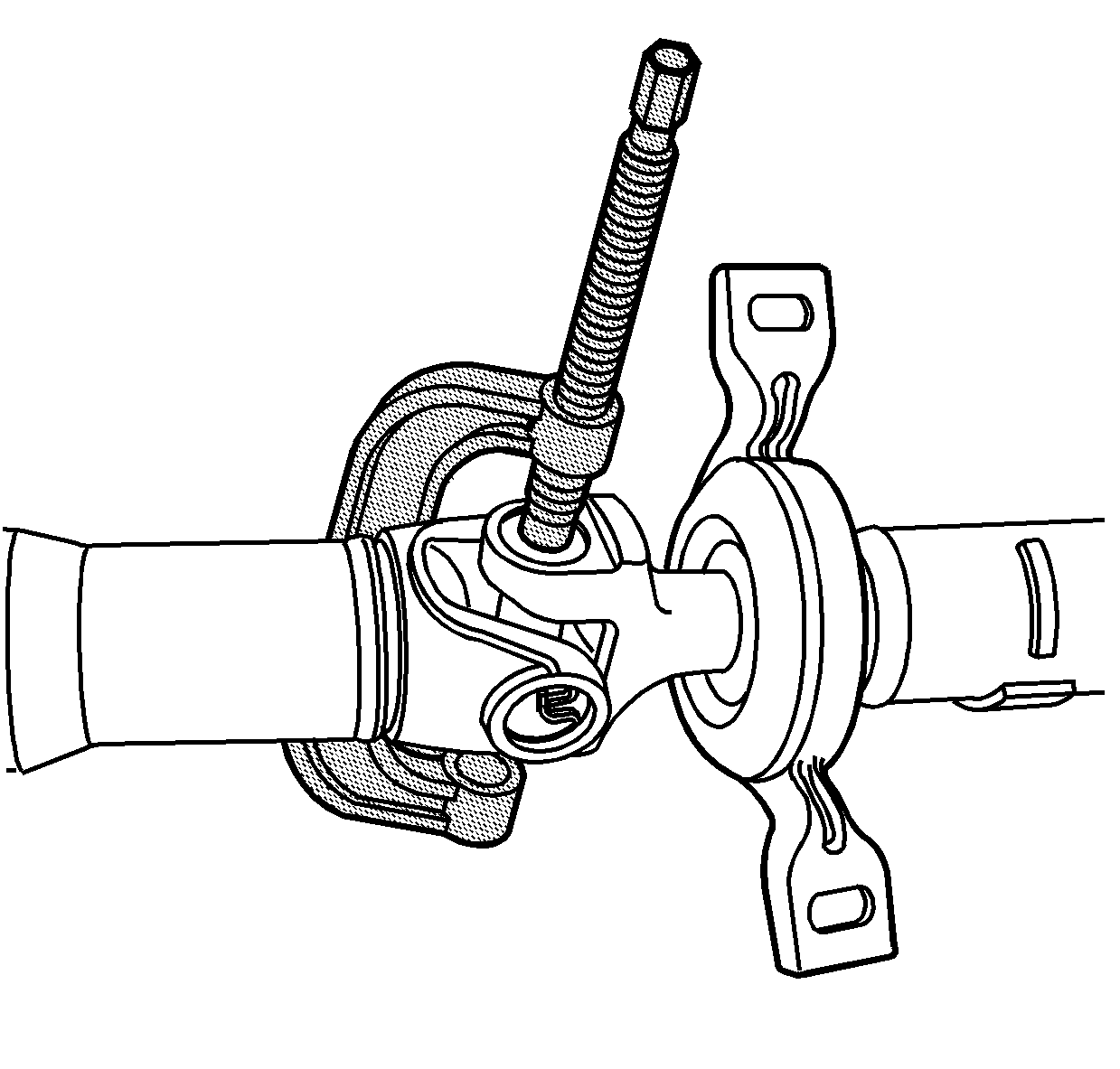
- Remove the universal joint caps using J 45270 .
- Remove the front shaft half.
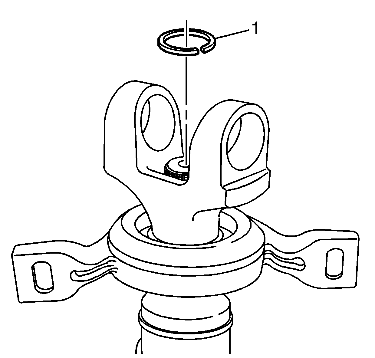
- Remove the lock ring (1) from the groove.
- Discard the lock ring.
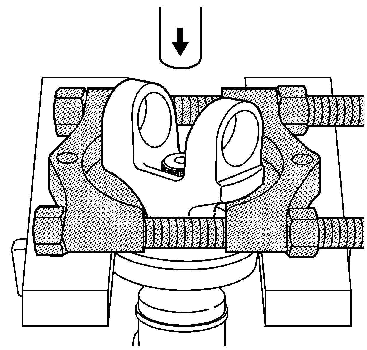
- Place J 22912-B on the splined yoke, as illustrated.
- Using a press, remove the yoke.
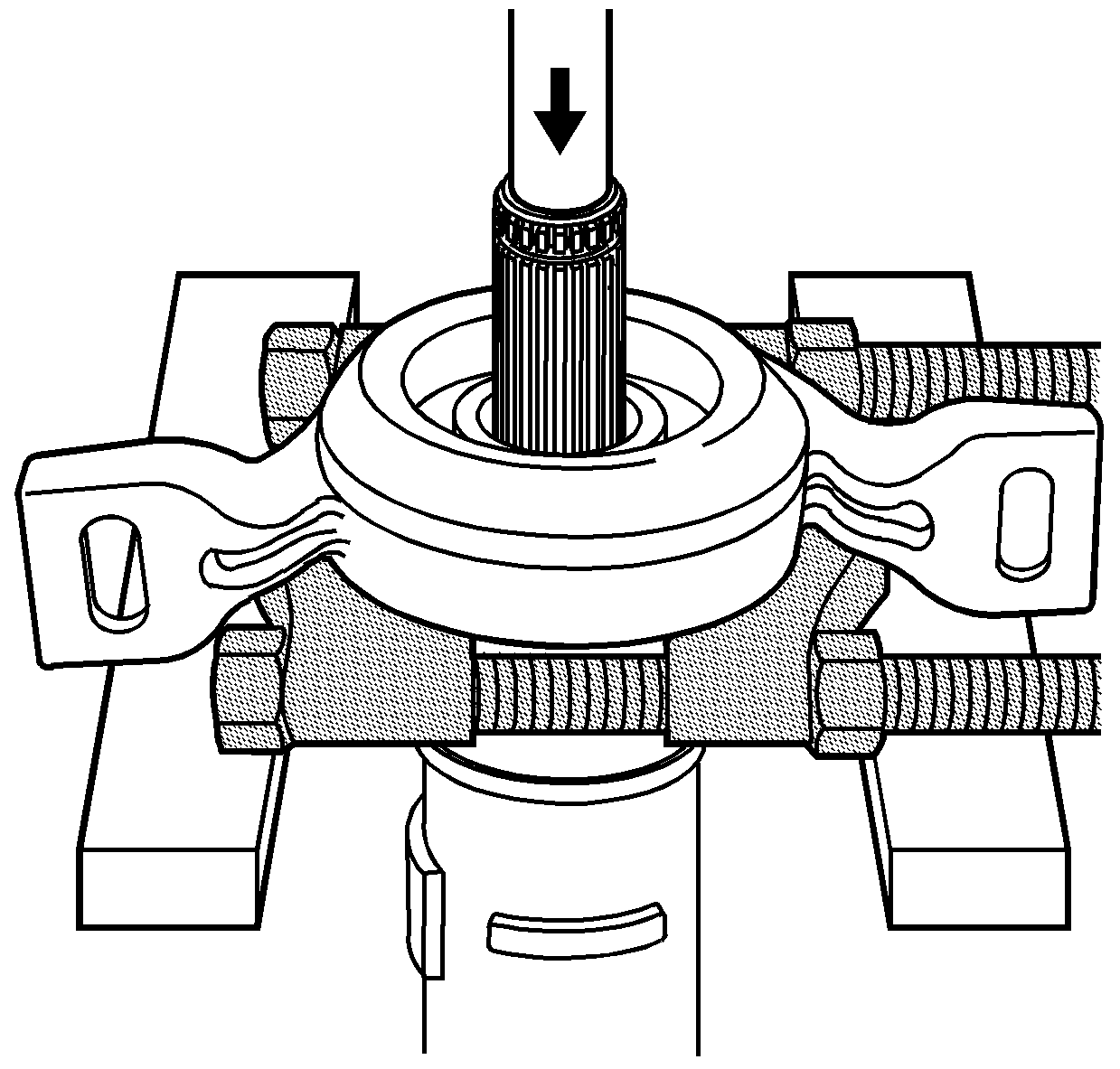
- Place J 22912-B behind the support bearing.
- Place the shaft in a press; then, support J 22912-B and press off the support bearing.
Notice: Never clamp propeller shaft tubing in a vise. Clamping propeller shaft tubing in a vise could dent or deform the tube, causing an imbalance or unsafe condition. Always clamp on one end of the yokes and support the shaft horizontally.
Important: Prior to disassembly, mark the positions of the driveshaft components relative to the driveshaft tube. All components must be reassembled in the same relationship to maintain proper balance.
| 1.1. | Pinch the ends of the snap ring together with a pair of pliers. |
| 1.2. | If the snap ring does not readily snap out of the groove in the yoke, tap the end of the bearing cup lightly in order to relieve pressure from ring. |
