For 1990-2009 cars only
Installation Procedure
Tools Required
| • | J 28467-B Universal Engine Support Fixture |
| • | J-28467-13 Engine Support Fixture Adapters |
| • | J 42451-1 Engine Support Adapter |
| • | J 36462-A Engine Support Adapter Leg Set |
| • | J 28467-7A Bolt Hook |
| • | J 28467-34 Lift Hook Wing Nut & Washer |
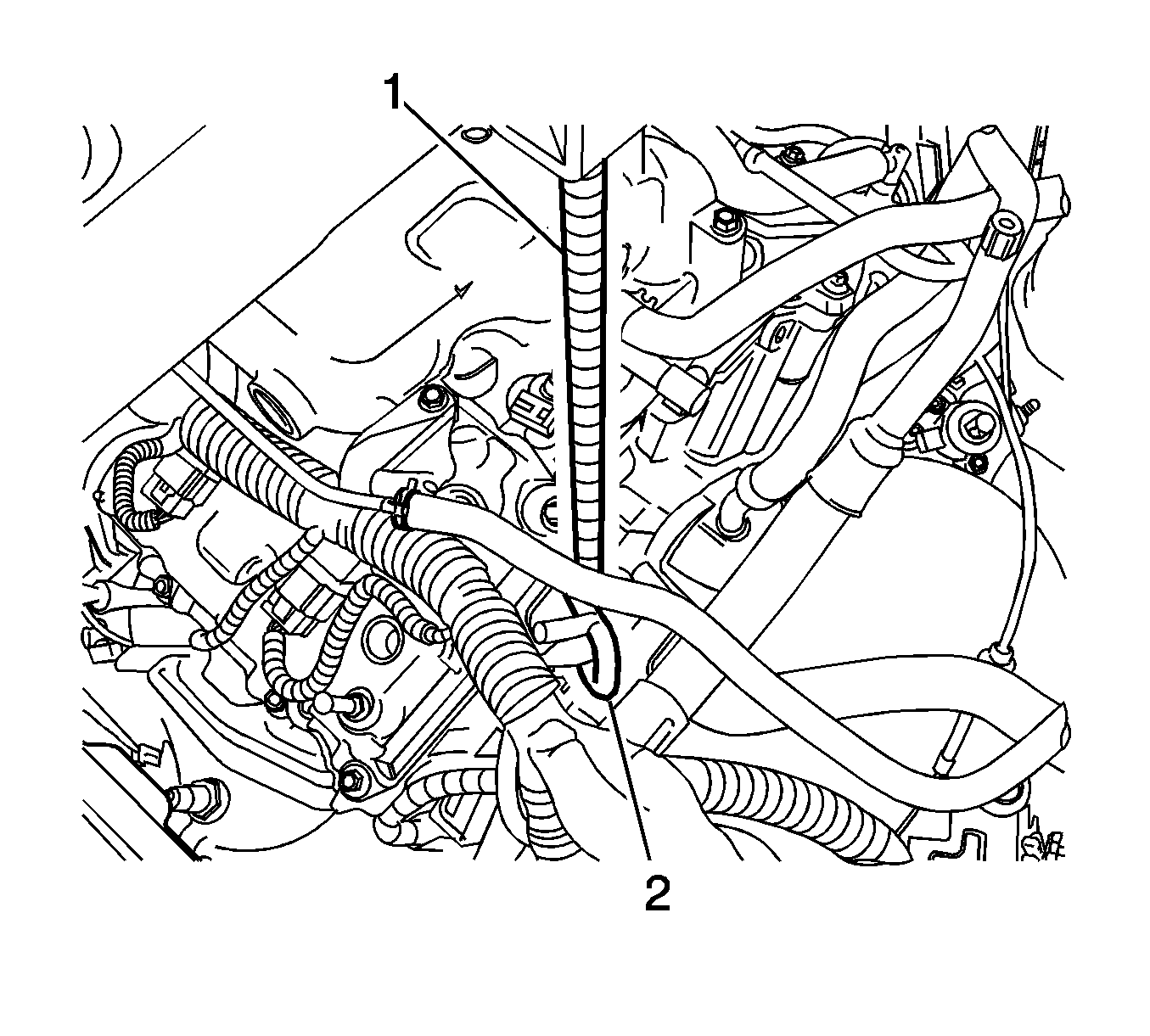
- Remove the fuel injector sight shield. Refer to Fuel Injector Sight Shield Replacement.
- Pull each end of the hood rear seal away from the cowl panel flange near both strut towers.
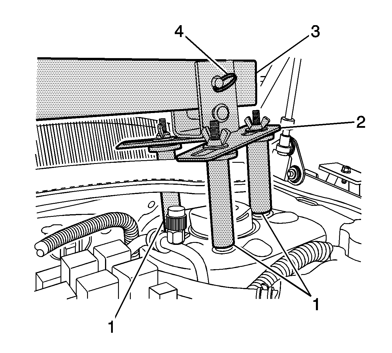
- Install three J-28467-13 (1) and two J 28467-5 strut tower adapters (2) to the top of the left and right strut tower.
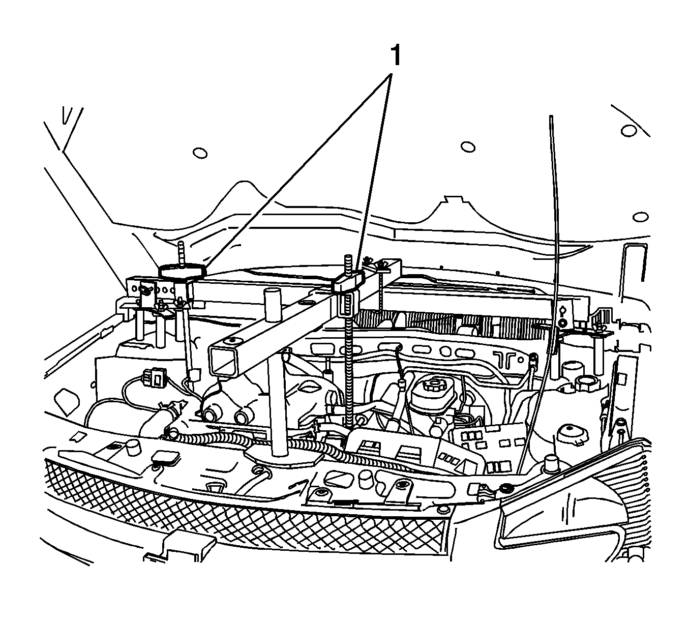
- Install a 127 cm (50 in) engine support fixture cross bar J-28467-B (3) transversely across the vehicle between both J 28467-5 strut tower adapters (2).
- Insert safety pins J-28467-10 (4) through the J 28467-5 strut tower adapters (2) and the cross bar (3) to prevent movement.
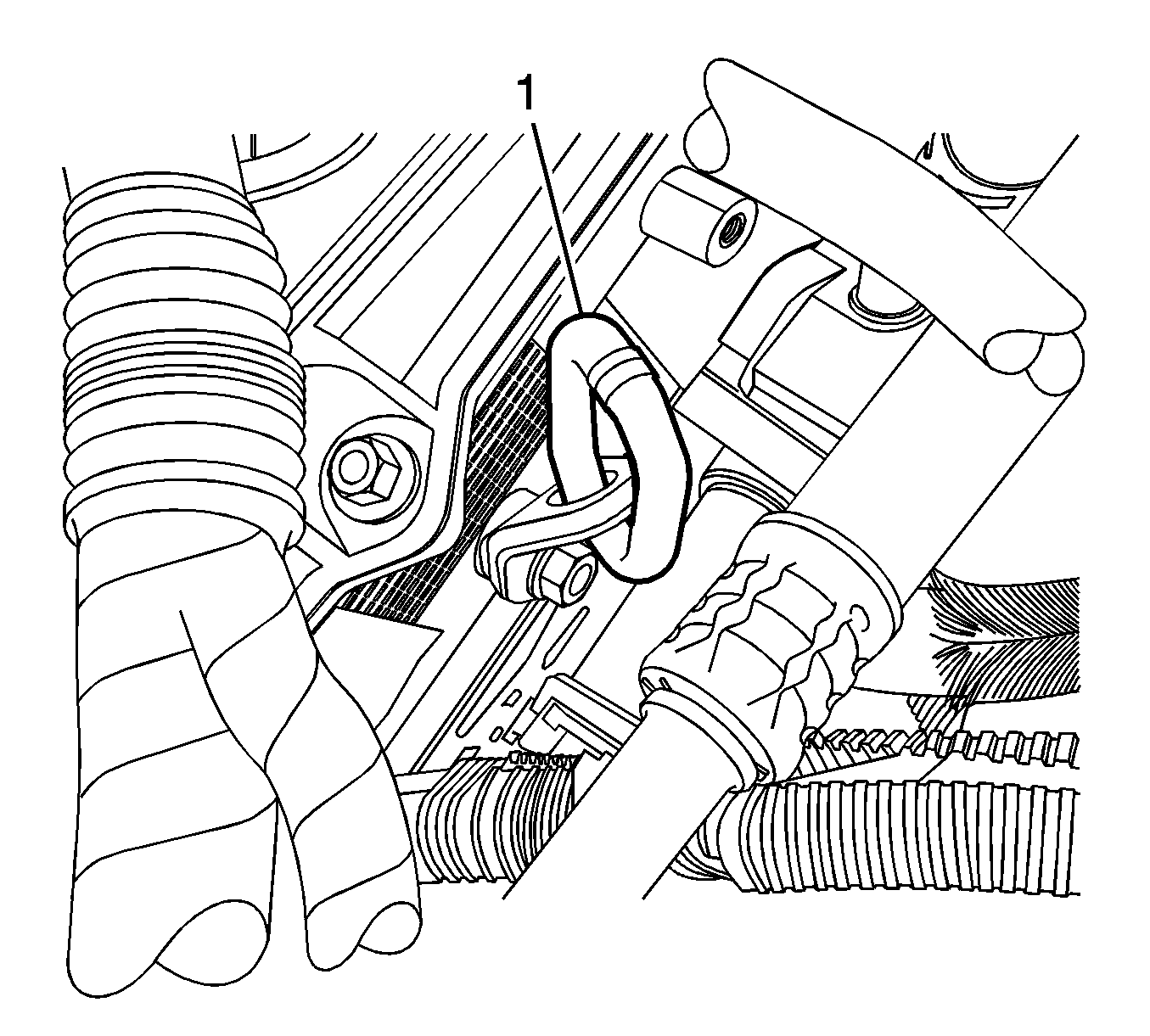
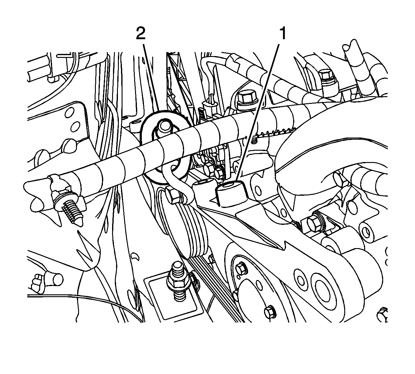
- Install the engine support bracket J-42451-1 (1) J 42451-1 to the engine.
- Remove the engine strut mount bracket. Refer to Engine Mount Strut Bracket Replacement - Right Side.
- Reinstall the engine mount strut bracket (1) and J-42451-1 (2) J 42451-1 .
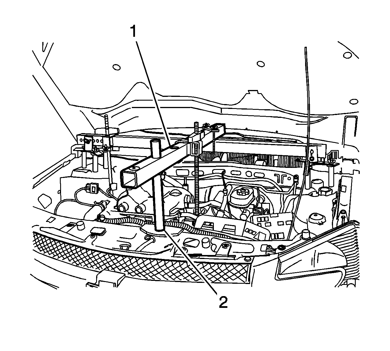
- Position the 58 cm (23 in) engine support fixture cross bar (1) longitudinally with the J 36462-A leg assembly (2).
- Install the J 28467-1A clamp (3) to secure the longitudinal mounted cross bar to the transverse mounted cross bar.
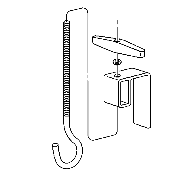
- Assemble the lift hook wing nut J-28467-34 and the lift hook bracket J-28467-6A to the lift hook J-28467-7A.
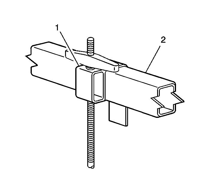
- Install the lift hook and bracket assembly (1) to the longitudinal mounted cross bar (2).
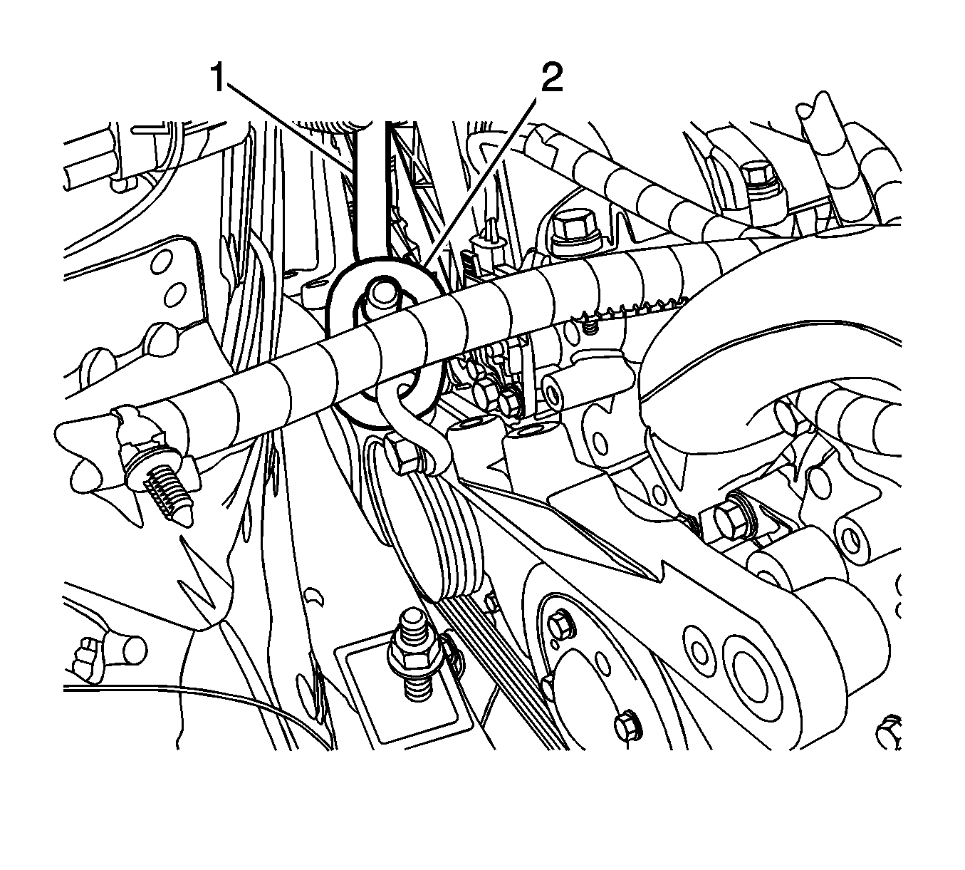
- Position the J 28467-7A lift hook (1) to the rear engine lift bracket J-42451-1 (2).
- Assemble the lift hook wing nut J-28467-34 and the lift hook bracket J-28467-6A to the lift hook J-28467-7A.
- Install the lift hook and bracket assembly (1) to the longitudinal mounted cross bar (2).
- Position the J 28467-7A bolt hook (1) to the front engine lift bracket J-42451-1 (2).
- Evenly tighten both wing nuts J-28467-34 (1) until the engine weight is supported by the engine support fixture and no longer carried by the engine mounts.
Notice: Use the correct fastener in the correct location. Replacement fasteners must be the correct part number for that application. Fasteners requiring replacement or fasteners requiring the use of thread locking compound or sealant are identified in the service procedure. Do not use paints, lubricants, or corrosion inhibitors on fasteners or fastener joint surfaces unless specified. These coatings affect fastener torque and joint clamping force and may damage the fastener. Use the correct tightening sequence and specifications when installing fasteners in order to avoid damage to parts and systems.
Tighten
Tighten the bolts to 50 N·m (37 lb ft).
