For 1990-2009 cars only
Removal Procedure
- Remove the fuel injector sight shield. Refer to Fuel Injector Sight Shield Replacement .
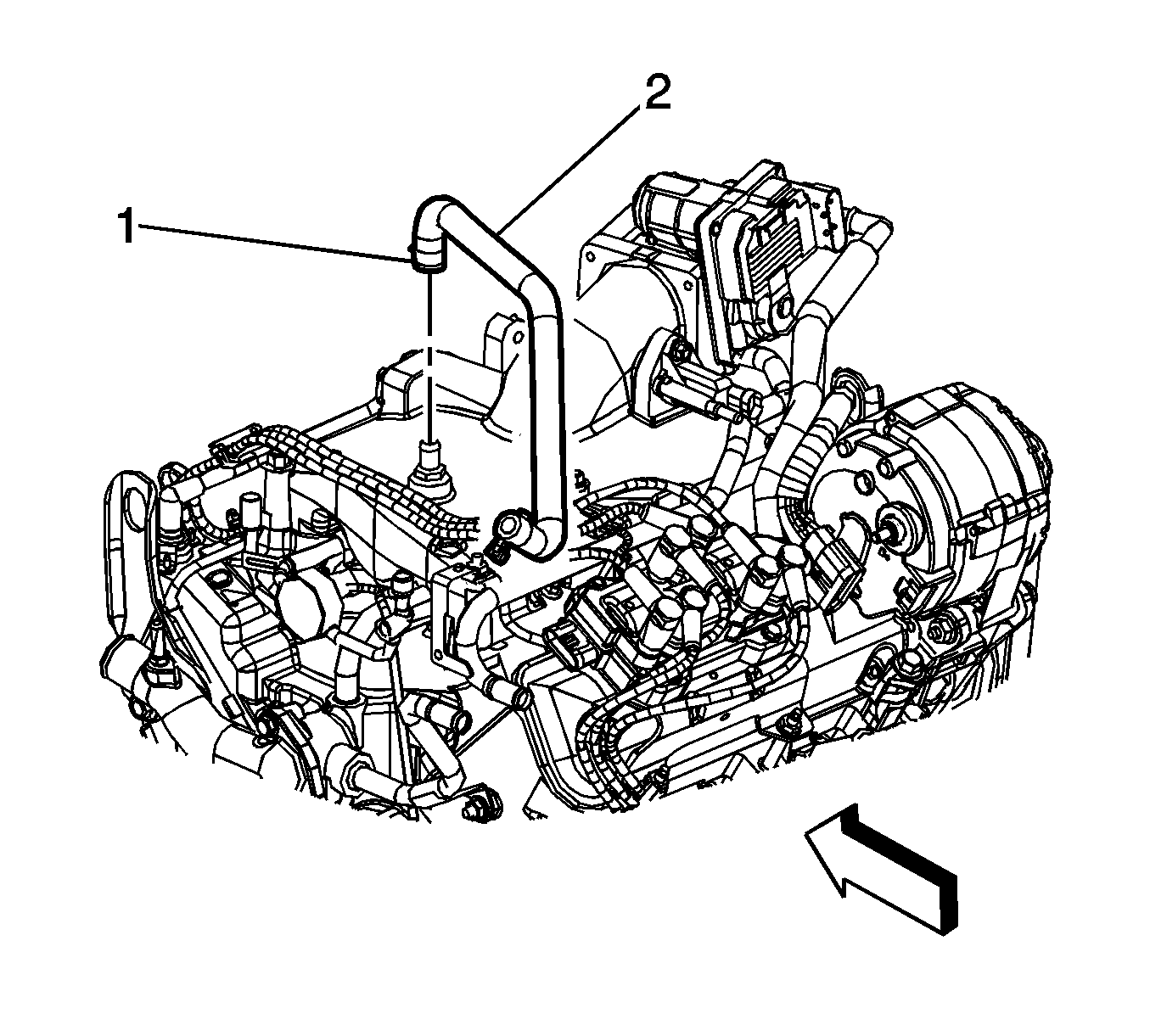
- Release the clamp (1) from the brake booster vacuum hose connection.
- Disconnect the brake booster vacuum hose (2) from the intake manifold.
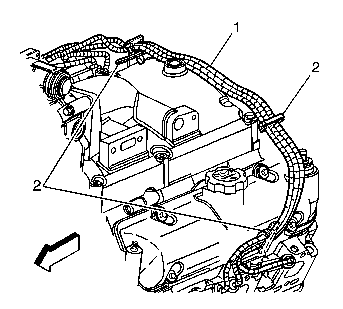
- Disconnect the left side spark plug wires (1) from the retainers (2) and from the spark plugs. Refer to Spark Plug Wire Replacement .
- Remove the ignition control module bracket from the engine with the ignition control module and spark plug wires still attached. Position out of the way. Refer to Ignition Control Module Bracket Replacement .
- Remove the air cleaner intake duct. Refer to Air Cleaner Inlet Duct Replacement .
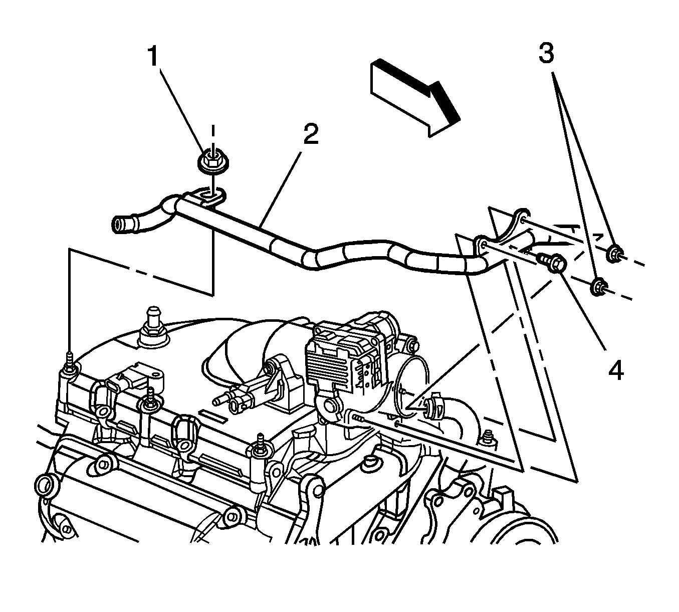
- Remove the heater outlet pipe nut (4) from the upper intake manifold.
- Remove the heater outlet pipe nuts (2) and bolt (3) from the throttle body.
- Position the heater outlet pipe out of the way without disconnecting the heater hoses.
- Remove the exhaust gas recirculation (EGR) pipe. Refer to Exhaust Gas Recirculation Pipe Replacement .
- Remove the positive crankcase ventilation (PCV) foul air hose. Refer to Positive Crankcase Ventilation Hose/Pipe/Tube Replacement .
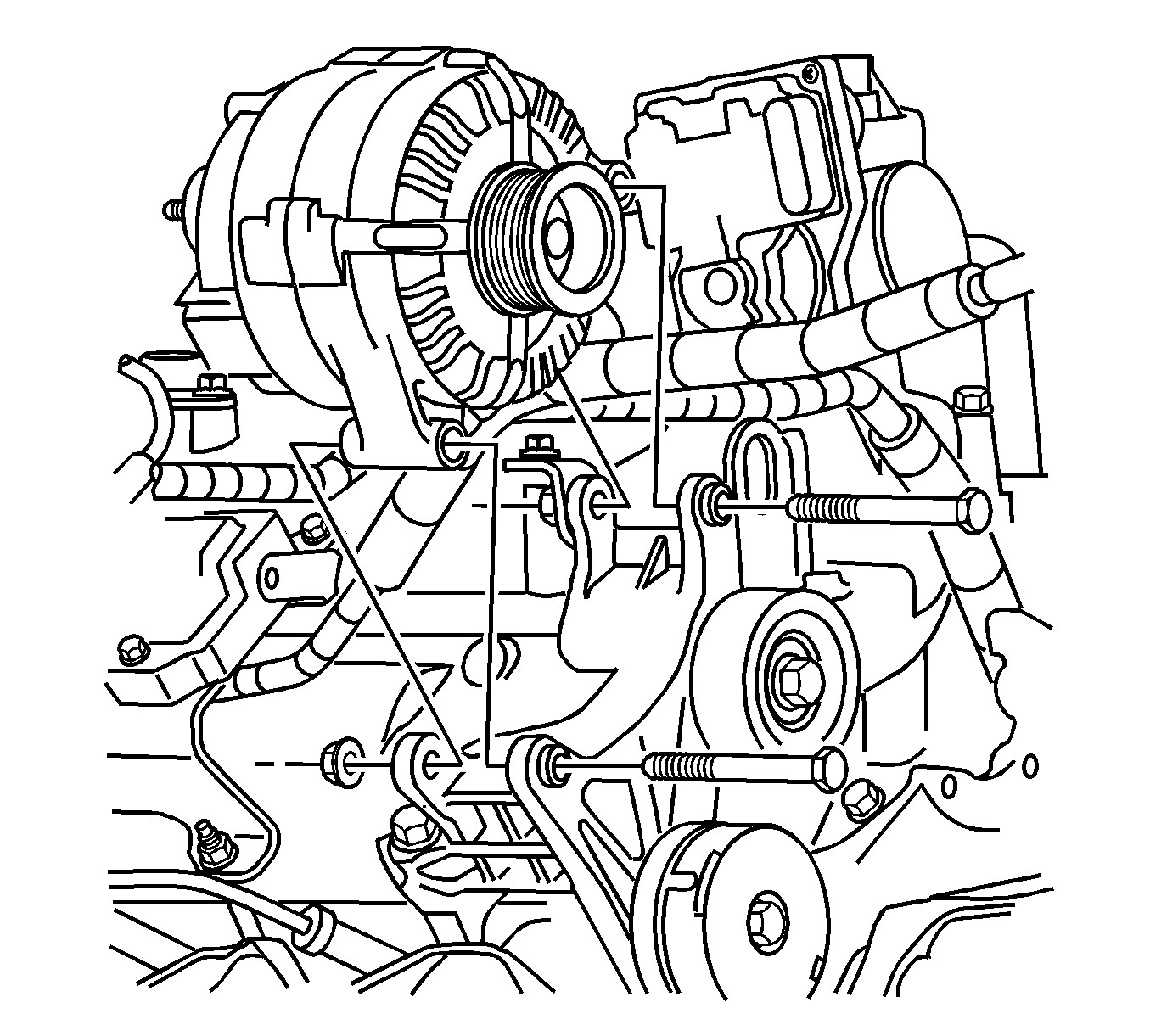
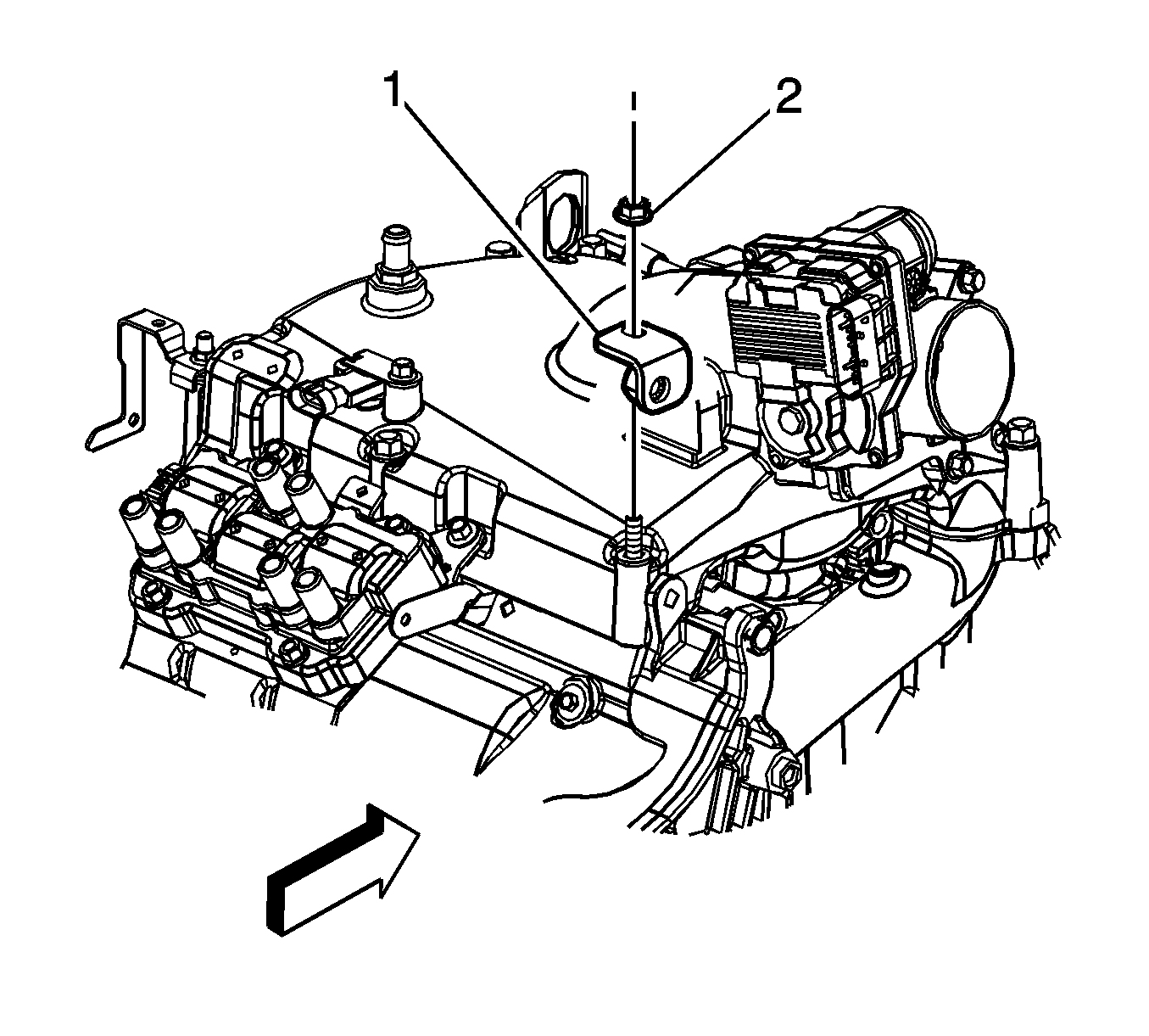
- Loosen but do not completely remove the generator attachment bolt most near the intake manifold.
- Remove the generator brace nut (2).
- Remove the generator brace (1).
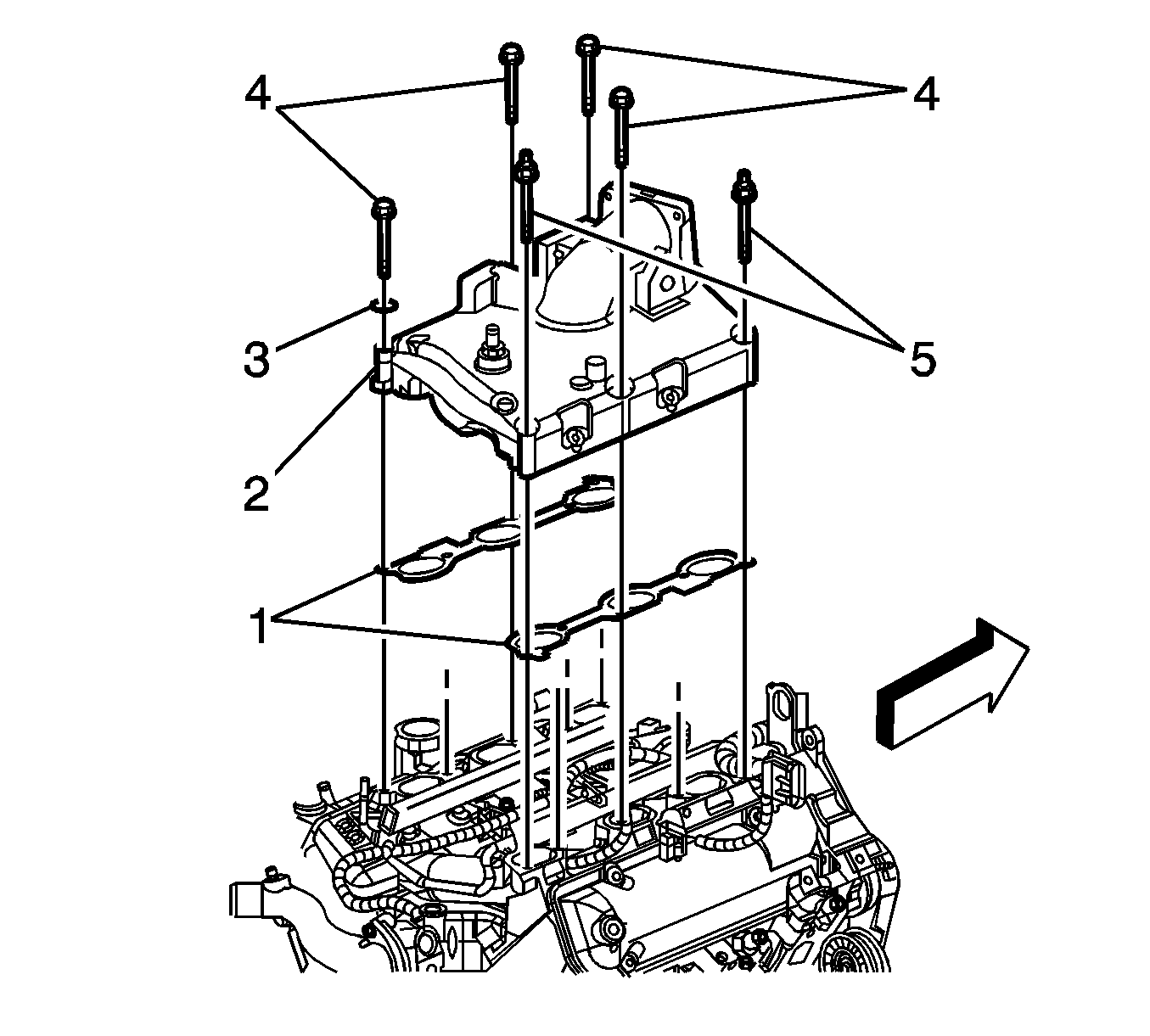
- Remove the upper intake manifold bolts (4, 5).
- Remove the spark plug wire retainer (3).
- Remove the upper intake manifold (2).
- Remove the upper intake manifold gaskets (1).
- If replacing the upper intake manifold complete the following steps:
| 19.1. | Remove the manifold absolute pressure (MAP) sensor. Refer to Manifold Absolute Pressure Sensor Replacement . |
| 19.2. | Remove the EGR valve. Refer to Exhaust Gas Recirculation Valve Replacement . |
| 19.3. | Remove the evaporative emissions (EVAP) purge solenoid valve. Refer to Evaporative Emission Canister Purge Solenoid Valve Replacement . |
| 19.4. | Remove the throttle body. Refer to Throttle Body Assembly Replacement . |
| 19.5. | Remove the fuel injector sight shield studs. Refer to Fuel Injector Sight Shield Replacement . |
Installation Procedure
- Install the upper intake manifold gaskets (1) to the lower intake manifold and install the fir tree retainers to retain the upper intake manifold gasket position.
- Install the upper intake manifold (2).
- Install the spark plug wire retainer (3).
- Apply threadlock GM P/N 12345382 (Canadian P/N 10953489) to the bolt threads. Install the upper intake manifold bolts (4, 5).
- If the upper manifold was replaced, complete the following steps:
- Install the generator brace (1).
- Install the generator brace nut (2).
- Fully insert the generator attachment bolt most near the intake manifold.
- Install the PCV foul air hose. Refer to Positive Crankcase Ventilation Hose/Pipe/Tube Replacement .
- Install the EGR pipe. Refer to Exhaust Gas Recirculation Pipe Replacement .
- Position the heater outlet pipe to the throttle body and the upper intake manifold.
- Install the heater outlet pipe nuts (2) to the throttle body.
- Install the heater outlet pipe bolt (3) to the throttle body.
- Install the heater outlet pipe nut (4) to the upper intake manifold.
- Install the air cleaner intake duct. Refer to Air Cleaner Inlet Duct Replacement .
- Install the ignition control module bracket . Refer to Ignition Control Module Bracket Replacement .
- Connect the left side spark plug wires (1) to the spark plugs and to the spark plug wire retainers. Refer to Spark Plug Wire Replacement .
- Connect the brake booster vacuum hose (2) to the intake manifold.
- Install the clamp (1) to the brake booster vacuum hose connection.
- Install the fuel injector sight shield. Refer to Fuel Injector Sight Shield Replacement .

Notice: Refer to Fastener Notice in the Preface section.
Tighten
Tighten the bolts to 25 N·m (18 lb ft).
| 5.1. | Install the fuel injector sight shield studs. Refer to Fuel Injector Sight Shield Replacement . |
| 5.2. | Install the throttle body. Refer to Throttle Body Assembly Replacement . |
| 5.3. | Install the EVAP purge solenoid valve. Refer to Evaporative Emission Canister Purge Solenoid Valve Replacement . |
| 5.4. | Install the EGR valve. Refer to Exhaust Gas Recirculation Valve Replacement . |
| 5.5. | Install MAP sensor. Refer to Manifold Absolute Pressure Sensor Replacement . |

Tighten
Tighten the nut to 25 N·m (18 lb ft).

Tighten
Tighten the bolt to 25 N·m (18 lb ft).

Tighten
Tighten the nut to 10 N·m (89 lb in).
Tighten
Tighten the bolt to 10 N·m (89 lb in).
Tighten
Tighten the nut to 25 N·m (18 lb ft).


