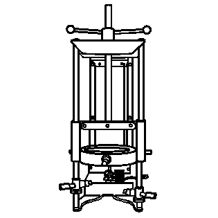
Tools Required
| • | J 42991 Strut Rod Nut Socket |
| • | J 45400 Strut Spring Compressor |
Removal Procedure
- Install the strut assembly in the J 45400 using the following procedure.
- Compress the spring enough to unload the upper strut mount.
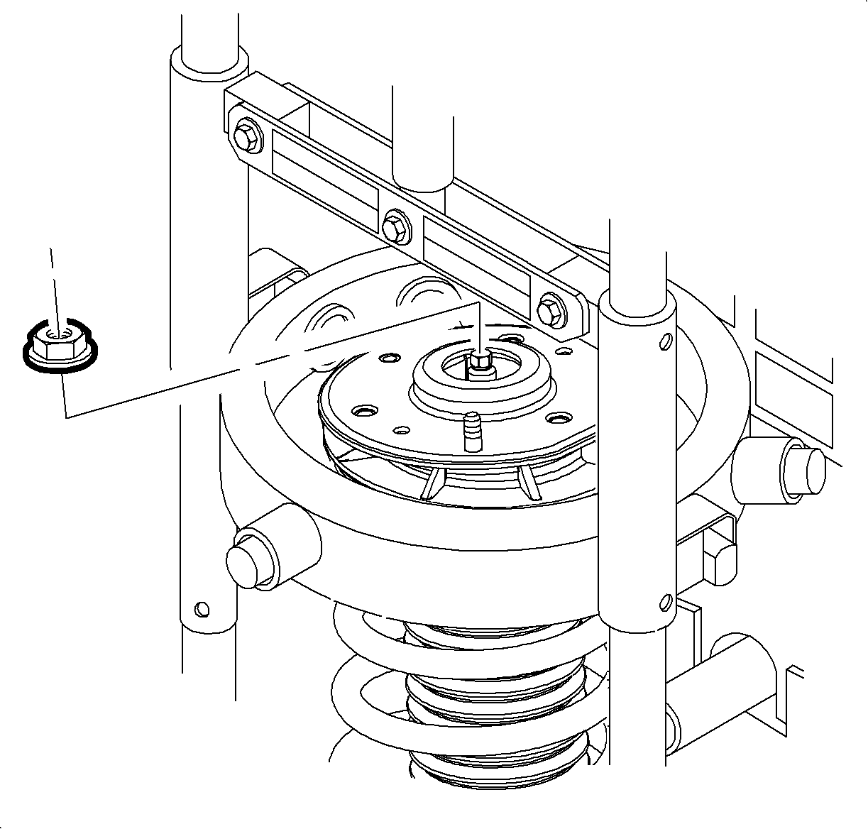
- Use the J 42991 or equivalent hand tools to remove the strut shaft nut.
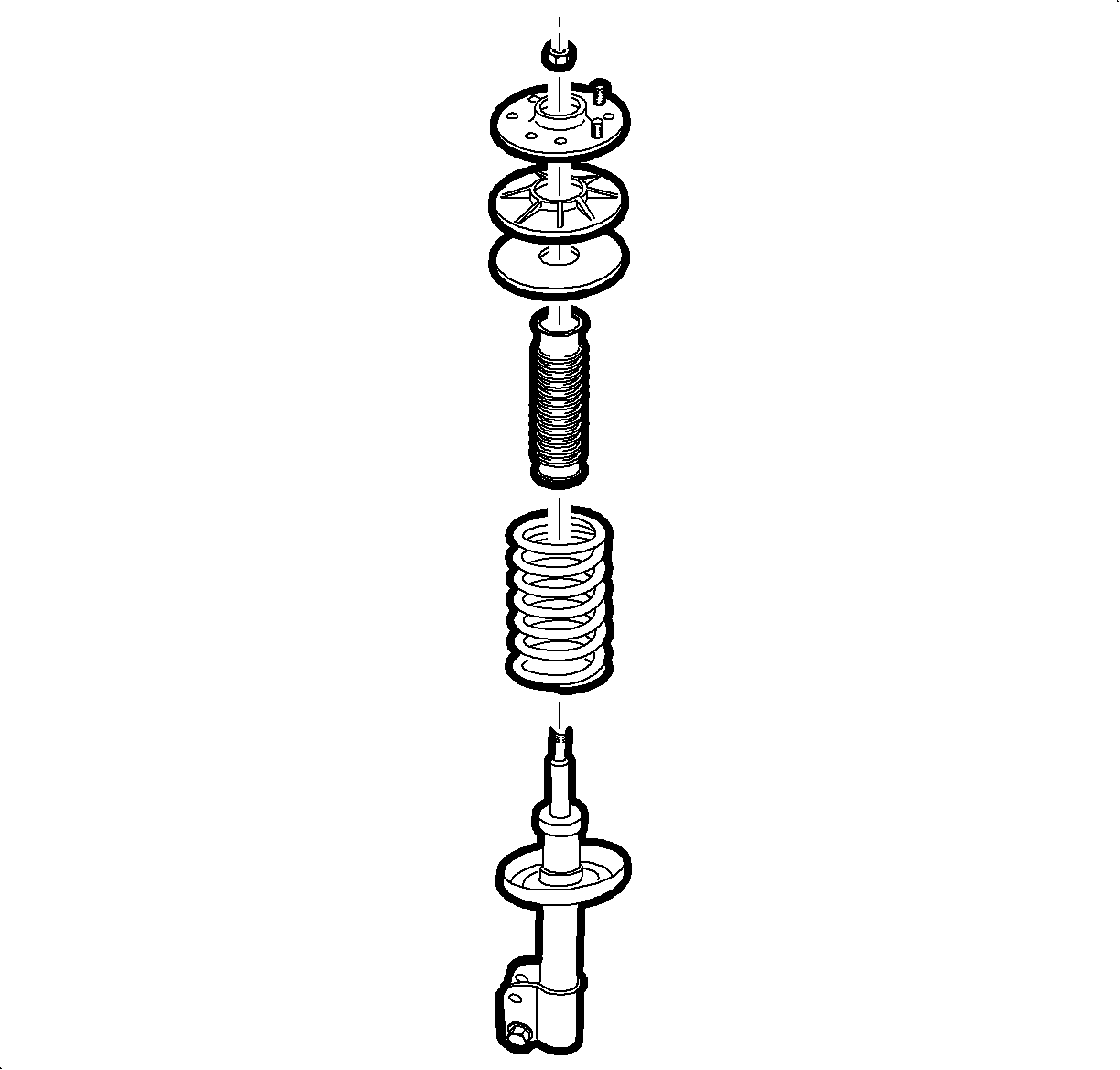
- Lower the strut from the spring assembly.
- Remove the upper mount assembly, inspect for damage and deterioration. Replace as necessary.
- Remove the strut dust shield and inspect for damage and deterioration. Replace as necessary.
- Remove the hollow bumper from the strut shaft and inspect for damage and deterioration. Replace as necessary.
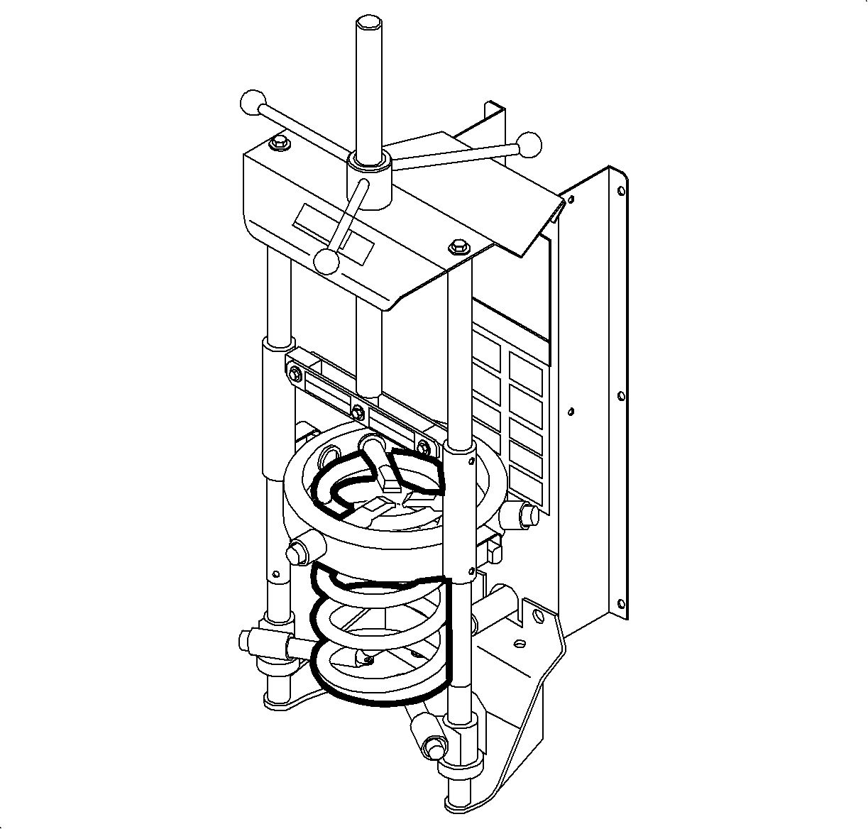
- Inspect the spring for damage. Replace as necessary.
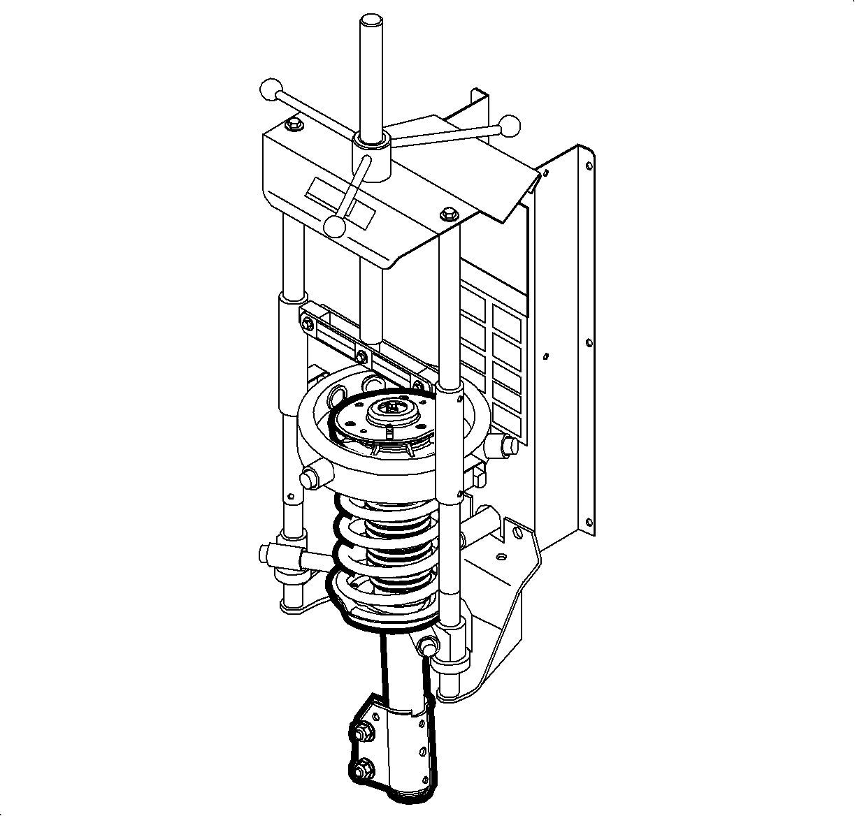
| 1.1. | Adjust the lower legs of the J 45400 to the lowest possible coil of the spring. |
| 1.2. | Adjust the upper legs of the J 45400 to the highest possible coil of the spring. |
| 1.3. | Inspect the strut assembly to insure hooks on the strut compress legs are properly installed on the spring coils. |
| 1.4. | Verify the strut assembly is parallel with the J 45400 . |
Notice: Do not allow the absorber rod to rotate during disassembly/reassembly. Use hand tools to keep the absorber rod from rotating. If air tools are used, and the rod is allowed to rotate, damage to the absorber may occur.
Important: Leave the spring in the spring compressor.
Notice: Do not handle the top mount assembly by the plastic portion. Handle the top mount assembly by the metal portion when removing/installing the top mount from/to the strut assembly. Holding the top mount assembly by the plastic portion may loosen the snap fit of the bearing components and cause the bearing to fall apart.
Installation Procedure
- Extend the strut to its limit of travel.
- Install the hollow bumper and dust boot to the strut shaft.
- With the spring in the compressor, install the strut into the spring.
- Assemble the upper spring seat onto the strut shaft and align the flat with the strut to knuckle mounting bracket.
- Assemble the top mount onto the strut shaft and align the flat 180 degrees from flat on the upper spring seat.
- Loosely install the strut shaft nut.
- Hold the strut shaft and use the J 42991 or equivalent hand tools to tighten the shaft while verifying that the upper spring seat flats align with the top mount.
- Release the tension on the J 45400 .
- Remove the strut assembly from the J 45400 .
Important: The tag identifying the spring will be closer to the bottom of the spring. The end of the coil sits up against the tab on the spring seat.
Important: The anti-rotation tab on the spring seat must face 180 degrees from the direction that the knuckle bracket points.
Notice: Do not handle the top mount assembly by the plastic portion. Handle the top mount assembly by the metal portion when removing/installing the top mount from/to the strut assembly. Holding the top mount assembly by the plastic portion may loosen the snap fit of the bearing components and cause the bearing to fall apart.
Important: The flat on the metal plate of the top mount assembly must face the same direction of the anti-rotation tab on the spring seat.
Notice: Refer to Fastener Notice in the Preface section.
Notice: Do not allow the absorber rod to rotate during disassembly/reassembly. Use hand tools to keep the absorber rod from rotating. If air tools are used, and the rod is allowed to rotate, damage to the absorber may occur.
Tighten
Tighten the strut shaft to 85 N·m (63 lb ft).
