Output Speed Sensor and Valve Body Installation
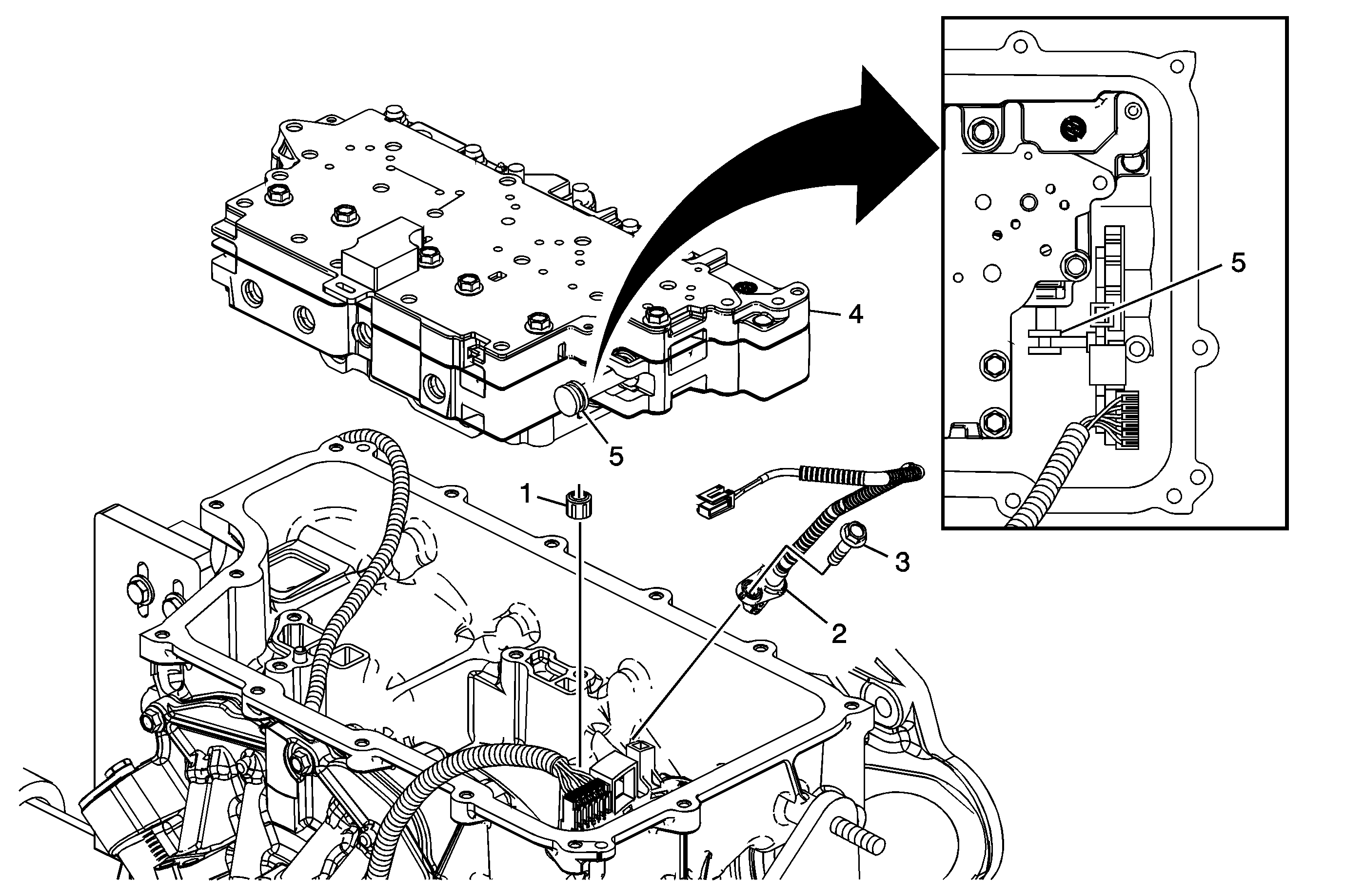
Callout | Component Name | ||||
|---|---|---|---|---|---|
1 | 1-2-3-4 Clutch Fluid Passage Seal | ||||
2 | A/Trans Output Speed Sensor Assembly | ||||
3 | A/Trans Output Speed Sensor Assembly Bolt M6 x 25 Notice: Refer to Fastener Notice in the Preface section. Tighten | ||||
4 | Control Valve Body Assembly | ||||
5 | Manual Valve Tip
Special ToolJ 41229 Manual Shaft Pin Installer |
Control Valve Body Bolts Installation
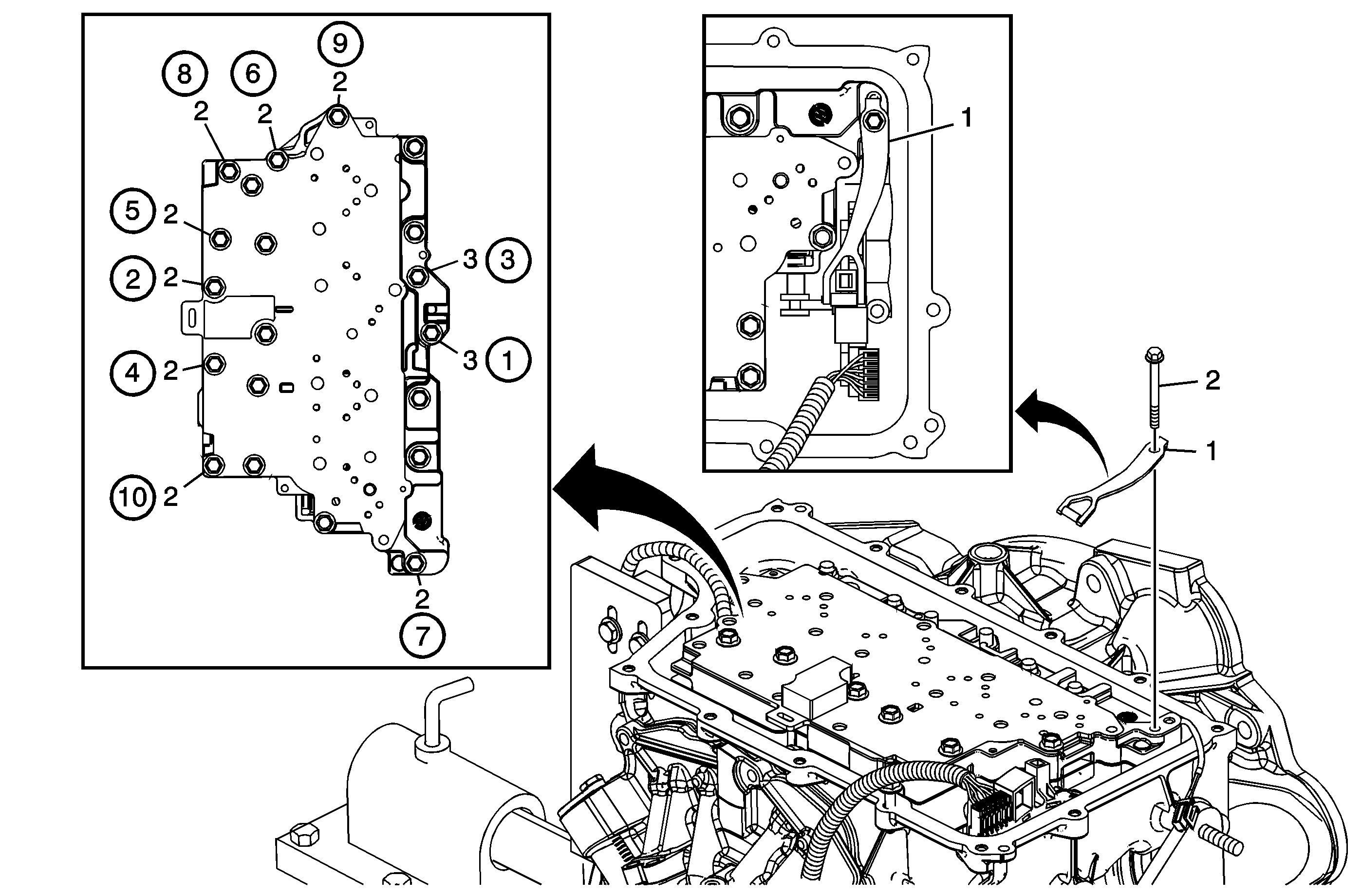
Callout | Component Name |
|---|---|
1 | Manual Shaft Detent Assembly Tip |
2 | Control Valve Body Bolt M6 x 65 (Qty: 8) Notice: Refer to Fastener Notice in the Preface section. ProcedureTighten in sequence to: Tighten |
3 | Control Valve Body Bolt M6 x 55 (Qty: 2) ProcedureTighten in sequence to: Tighten |
Filter Plate Installation
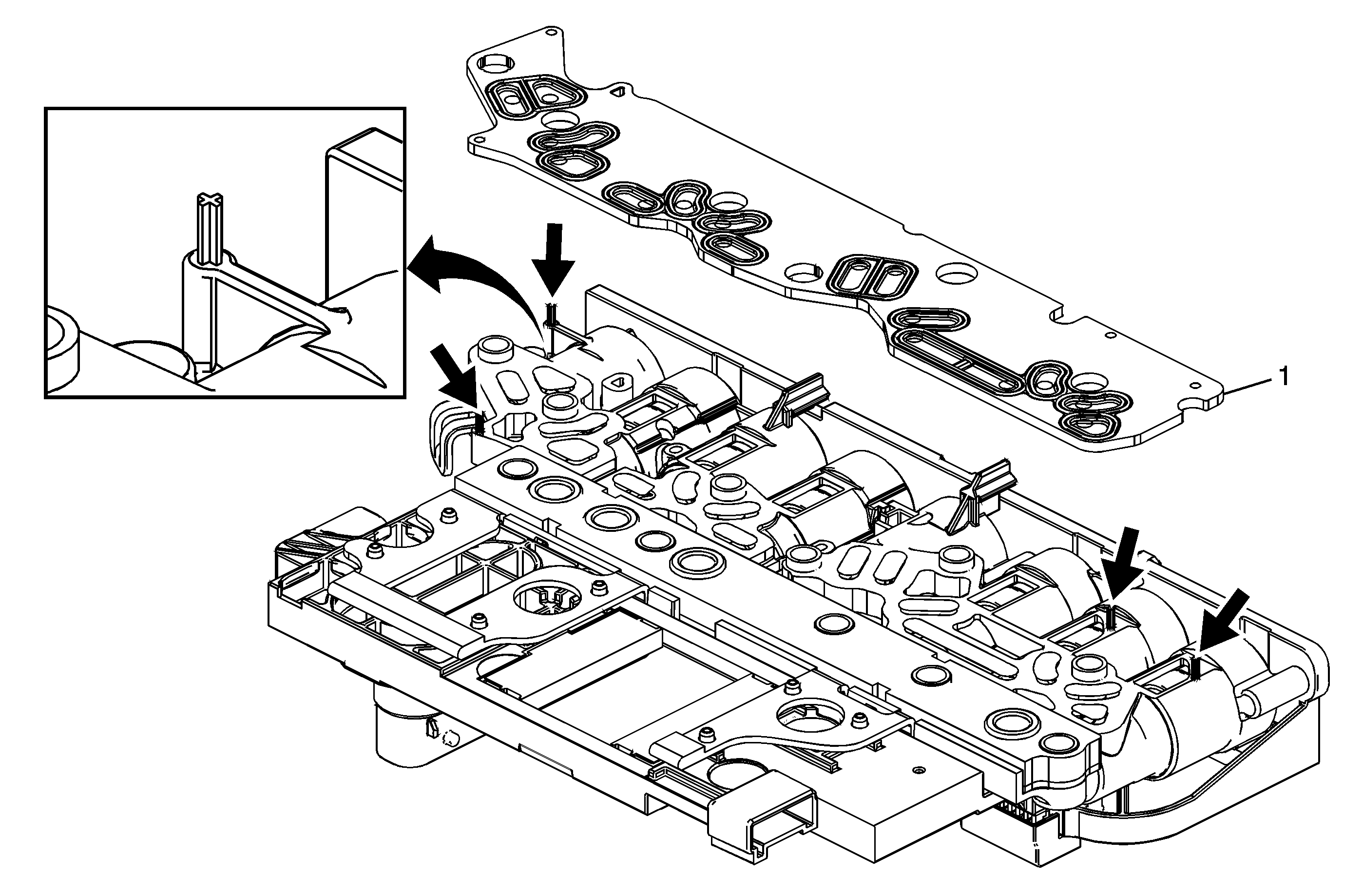
Callout | Component Name |
|---|---|
1 | Control Solenoid Valve Assembly Filter Plate Notice: Use care when removing or installing the filter plate assembly. A broken or missing retaining tab may not adequately secure the filter plate to the control solenoid valve assembly, resulting in possible damage or contamination. Tip |
Control Solenoid (w/Body and TCM) Valve Assembly Installation
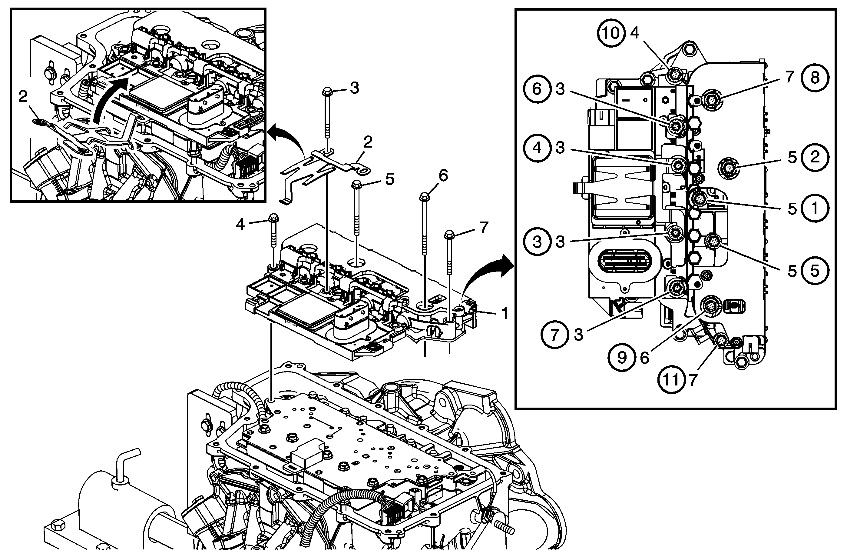
Callout | Component Name | ||||
|---|---|---|---|---|---|
|
Notice: Refer to Fastener Notice in the Preface section. Preliminary ProcedureInstall all bolts before tightening, then tighten in sequence to 12 N·m (9 lb ft). | |||||
1 | Control Solenoid (w/Body and TCM) Valve Assembly Notice: Do not drop the control solenoid with body and transmission control module (TCM) valve assembly. Internal damage can occur if the control solenoid with body and TCM valve assembly is dropped. DO NOT reuse the control solenoid with body and TCM valve assembly if it is dropped. | ||||
2 | Control Solenoid Valve Spring Tip
| ||||
3 | Control Valve Body Bolt M6 x 80 (Qty: 4) | ||||
4 | Control Valve Body Bolt M6 x 55 (Qty: 1) | ||||
5 | Control Valve Body Bolt M6 x 95 (Qty: 3) | ||||
6 | Control Valve Body Bolt M6 x 42 (Qty: 1) | ||||
7 | Control Valve Body Bolt M6 x 65 (Qty: 2) | ||||
Wire Routing and Connector Locations
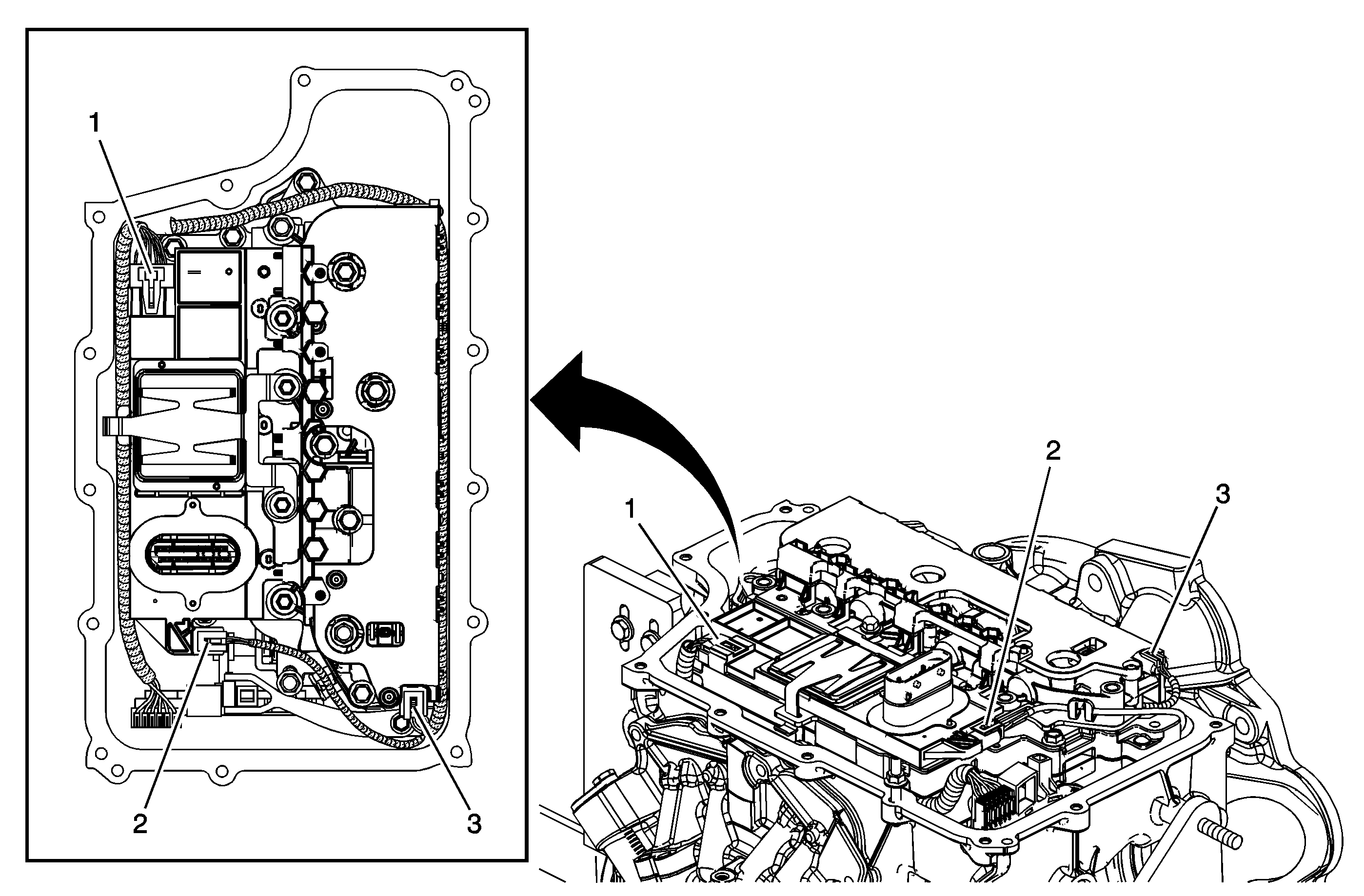
Callout | Component Name |
|---|---|
Preliminary ProcedureRoute all wires as shown. | |
1 | Shift Position Switch Connector |
2 | Output Speed Sensor Connector |
3 | Input Speed Sensor Connector |
Control Valve Body Cover Installation
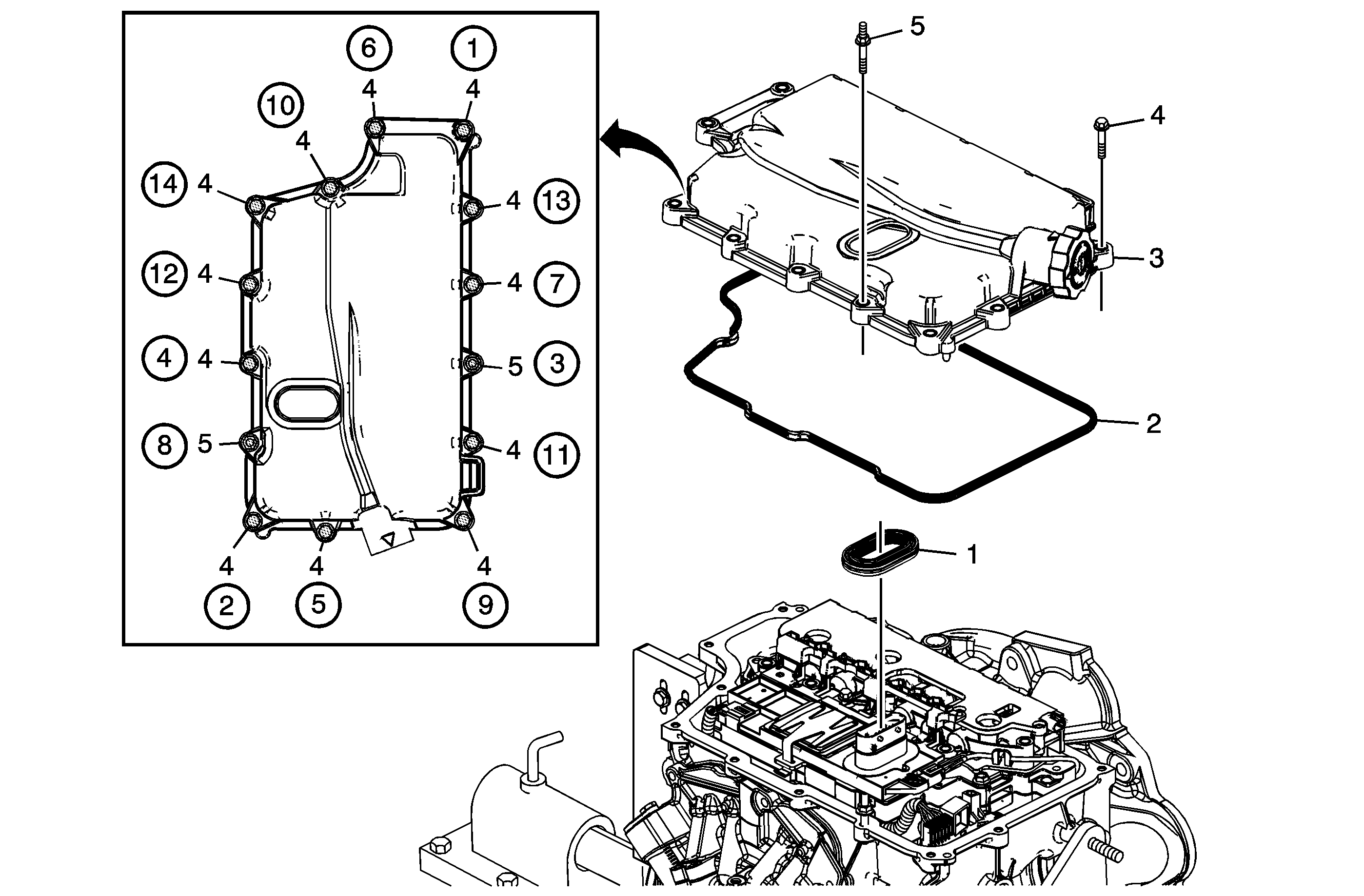
Callout | Component Name |
|---|---|
1 | Control Valve Body Cover Wiring Connector Hole Seal Tip |
2 | Control Valve Body Cover Assembly Gasket |
3 | Control Valve Body Cover Assembly |
4 | Control Valve Body Cover Bolt M6 x 30 (Qty: 12) Notice: Refer to Fastener Notice in the Preface section. ProcedureTighten in sequence to: Tighten |
5 | Control Valve Body Cover Stud M6 x 30 (Qty: 2) ProcedureTighten in sequence to: Tighten |
