Steering Gear Replacement EPS
Special Tools
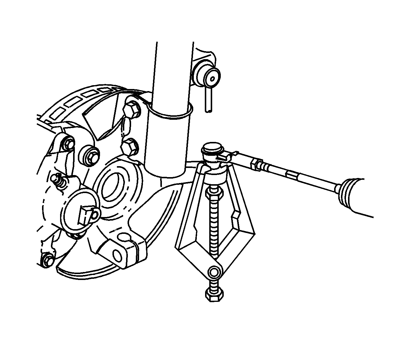
J 24319-B Steering Linkage and Tie Rod Puller
Removal Procedure
- Raise and support the vehicle. Refer to Lifting and Jacking the Vehicle.
- Remove the front tires. Refer to Tire and Wheel Removal and Installation.
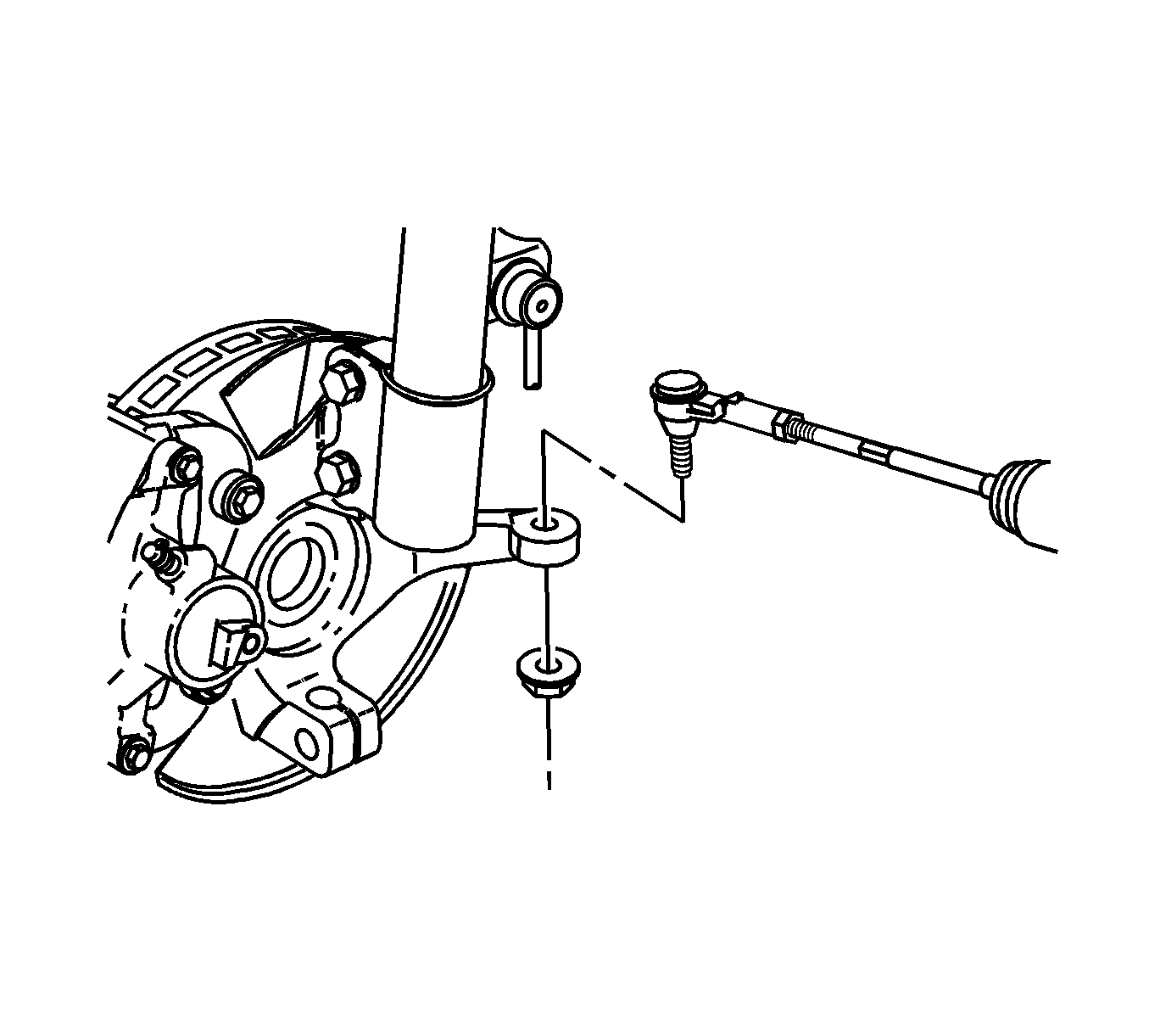
- Remove both outer tie rod to steering knuckle nuts. Discard the nuts.
- Using the J 24319-B , separate the tie rods from the steering knuckles.
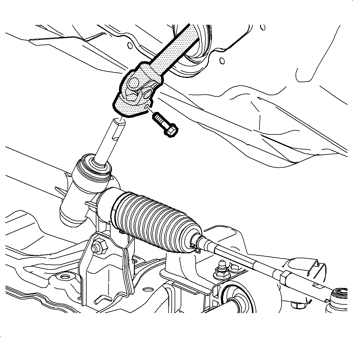
- Rotate the intermediate steering shaft in order to gain access to the intermediate shaft pinch bolt.
- Remove the intermediate to steering gear pinch bolt. Discard the bolt.
- Disconnect the intermediate shaft from the steering gear.
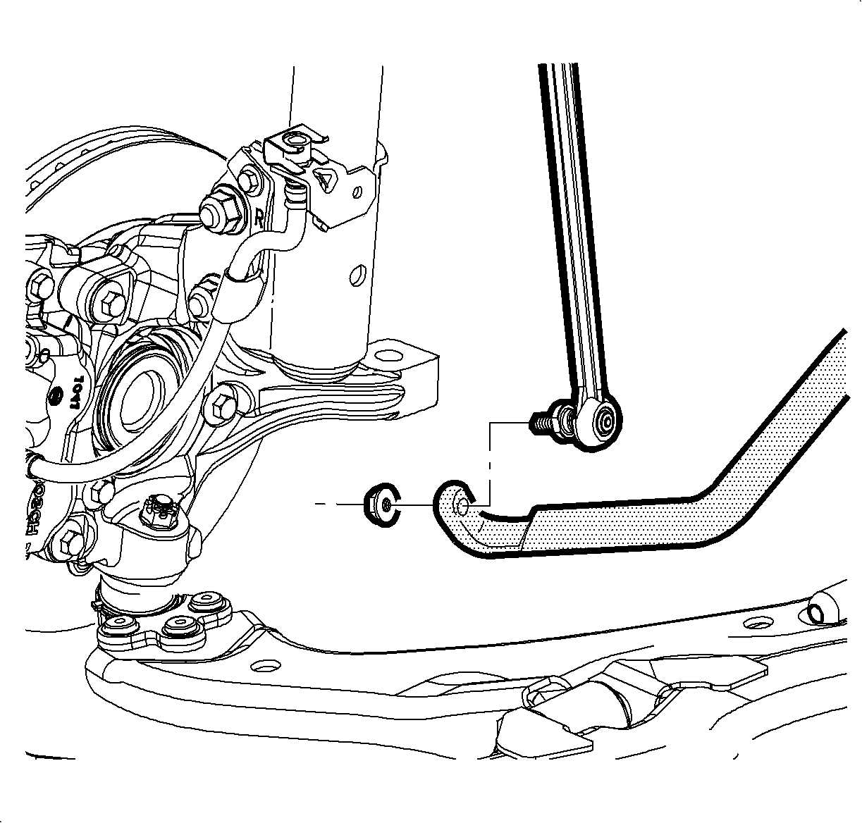
- Disconnect the stabilizer links from the stabilizer bar. Refer to Stabilizer Shaft Link Replacement.
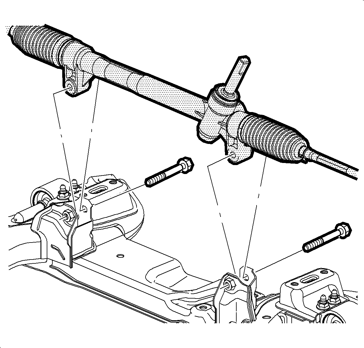
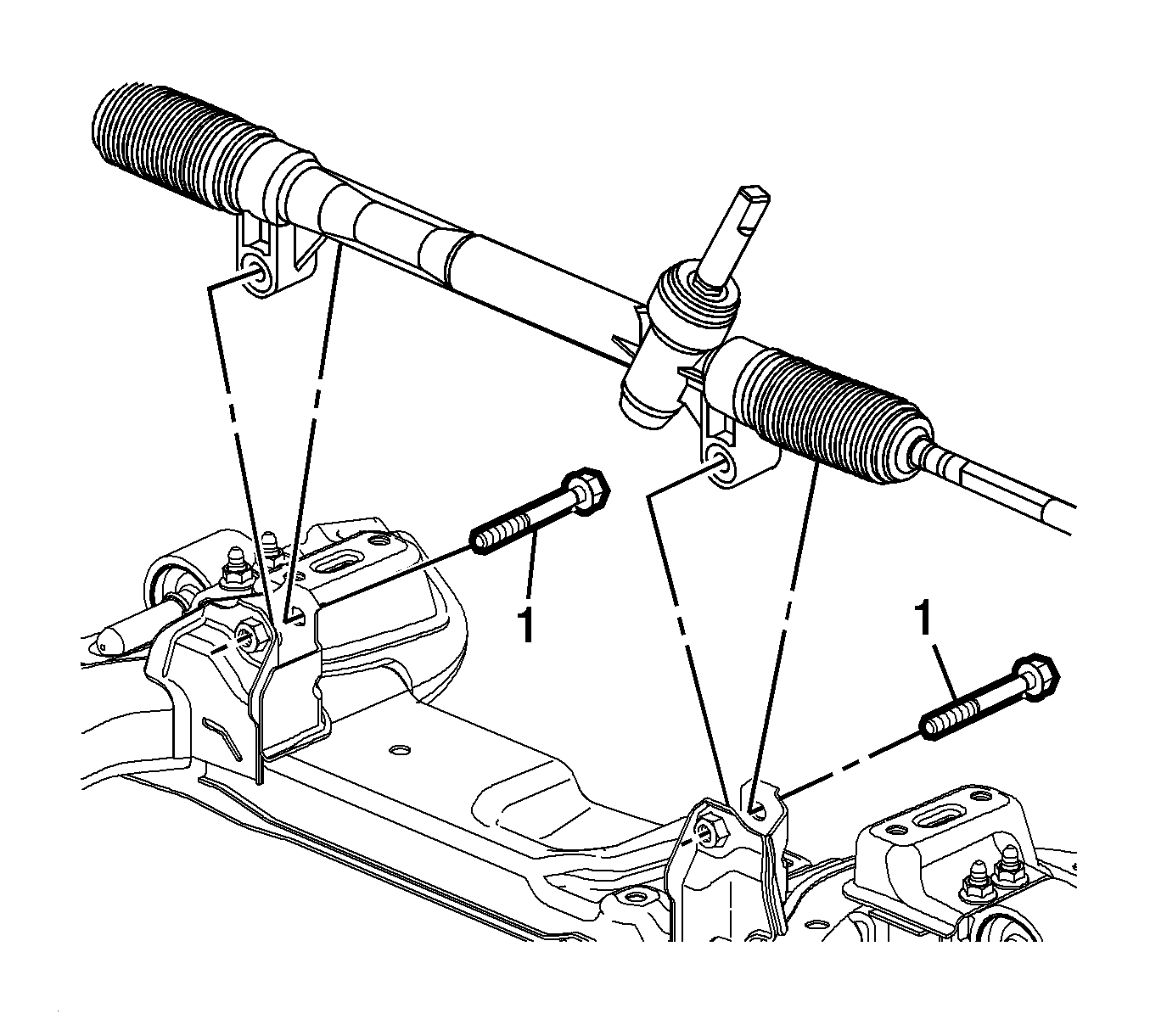
- Remove the steering gear to cradle mounting bolts.
- Remove the steering gear through the right side of the vehicle.
- With heat shield equipped steering gears, remove the heat shield. Save for installation.
Notice: Secure the steering wheel utilizing a strap to prevent rotation. Locking of the steering column will prevent damage and a possible malfunction of the SIR system. The steering wheel must be secured
in position before disconnecting the following components:
• The steering column • The intermediate shaft • The steering gear
Notice: Do not free the ball stud by using a pickle fork or a wedge-type tool. Damage to the seal or bushing may result.
Important: Hold the ball stud to prevent turning during removal of the nut.
Installation Procedure
- If applicable, install the heat shield.
- Install the steering gear from the right side of the vehicle.
- Center the gear mounting bushings into the cradle supports.
- Hand start both steering gear to cradle mounting bolts.
- Connect the intermediate shaft to the steering gear and install a new pinch bolt.
- Connect the stabilizer links to the stabilizer bar. Refer to Stabilizer Shaft Link Replacement.
- Connect the tie rod to the knuckle and install a new nut.
- Install the front tires and wheels. Refer to Tire and Wheel Removal and Installation.
- Check the front wheel alignment and align as necessary. Refer to Wheel Alignment Measurement.
- Lower the vehicle.
Important: Ensure the stabilizer is swung in the upmost position for gear clearance.
Notice: Refer to Fastener Notice in the Preface section.
Tighten
Tighten the bolts to 110 N·m (81 lb ft).
Tighten
Tighten the intermediate pinch bolt to 34 N·m (25 lb ft).
Important: Hold the ball stud to prevent turning during installation of the nut.
Tighten
Tighten the nut to 25 N·m (18 lb ft) plus 90 degrees.
Steering Gear Replacement HPS
Removal Procedure
- Disconnect the rack and pinion outer tie rods from the steering knuckles. Refer to Steering Linkage Outer Tie Rod Replacement.
- Remove the intermediate steering shaft lower bolt. Refer to Intermediate Steering Shaft Replacement.
- Place drain pans under the vehicle as needed.
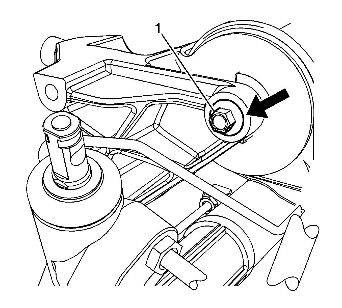
- Remove the transaxle mount bolt (1).
- Remove the transaxle mount bolts (1) and position the transaxle mount aside.
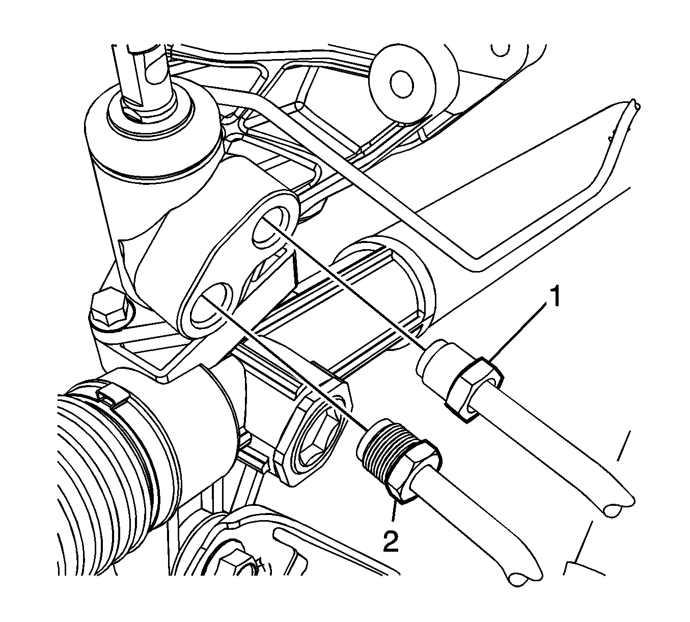
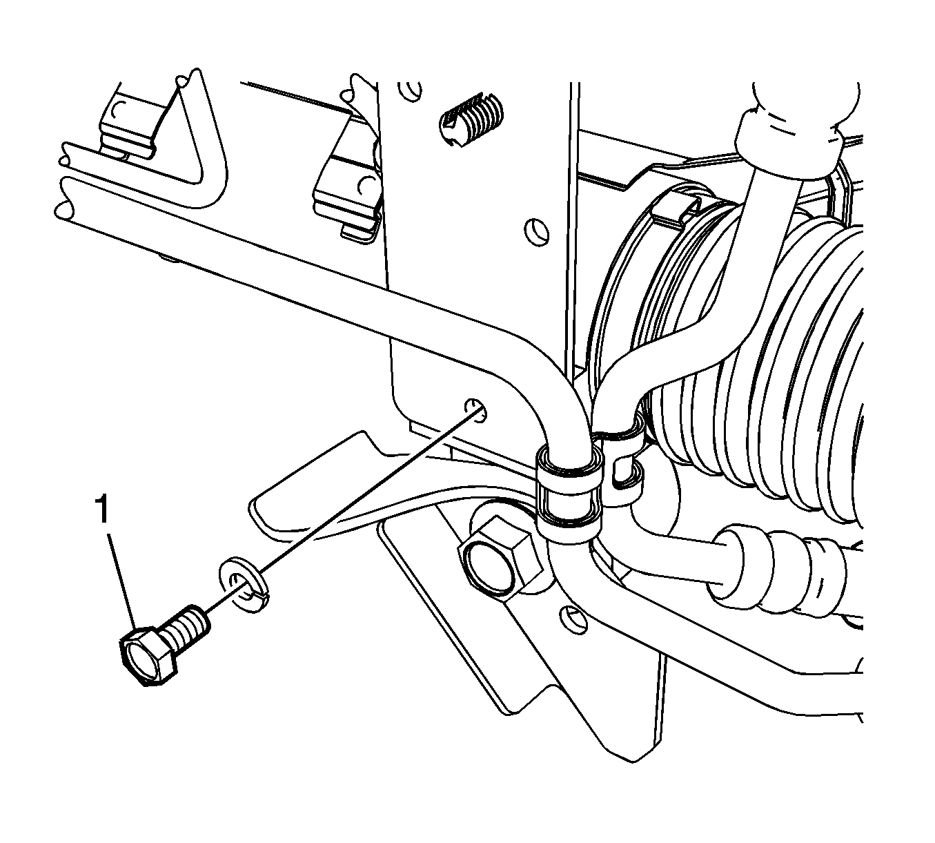
- Disconnect the power steering gear inlet hose (2) and the power steering cooler hose (1) from the power steering gear.
- Remove the power steering gear hoses bracket bolt (1).
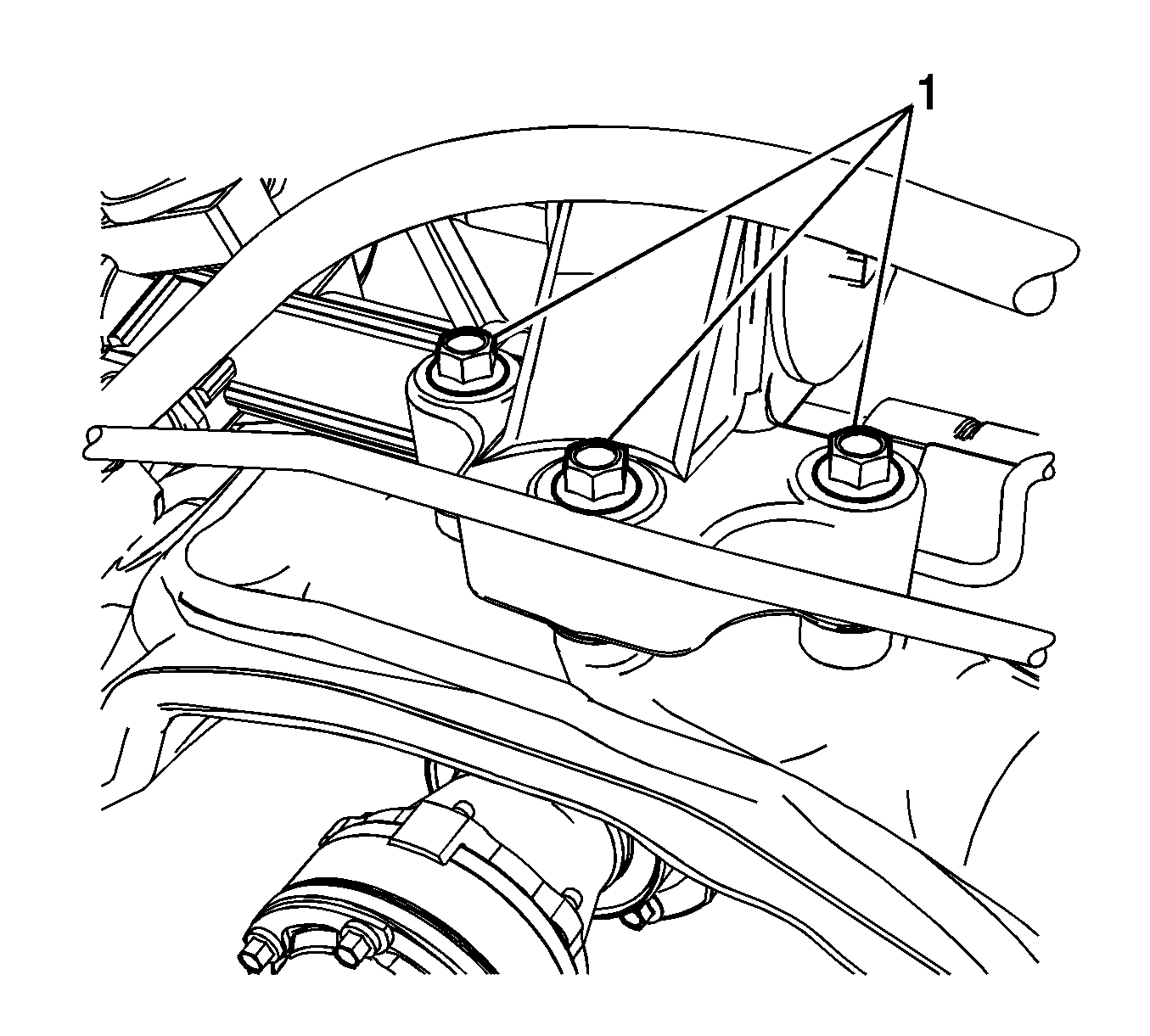
- Remove the power steering gear bolts (1).
- Remove the power steering gear through the left wheel house area.
- Transfer any parts as needed.
Important: Do not reuse the old O-Ring seals.
Installation Procedure
- Position the power steering gear into the vehicle through the left wheel house area.
- Install the power steering gear bolts (1).
- Install the power steering gear hoses bracket bolt (1).
- Connect the power steering gear inlet hose (2) and the power steering fluid cooler hose (1) to the power steering gear.
- Install the transaxle mount and transaxle mount bolts (1).
- Install the transaxle mount bolt (1).
- Clean any excess fluid from the vehicle and remove the drain pans.
- Install the intermediate steering shaft lower bolt. Refer to Intermediate Steering Shaft Replacement.
- Connect the rack and pinion outer tie rods to the steering knuckles. Refer to Steering Linkage Outer Tie Rod Replacement.
- Fill and bleed the power steering system. Refer to Power Steering System Bleeding.
- Adjust the front toe. Refer to Front Toe Adjustment.
Notice: Refer to Fastener Notice in the Preface section.
Tighten
Tighten to 110 N·m (81 lb ft).
Tighten
Tighten to 9 N·m (80 lb in).
Important: New O-Ring seals must be used to avoid potential leaks.
Tighten
Tighten to 25 N·m (18 lb ft).
Tighten
Tighten to 50 N·m (37 lb ft).
Tighten
Tighten to 110 N·m (81 lb ft).
