For 1990-2009 cars only
Removal Procedure
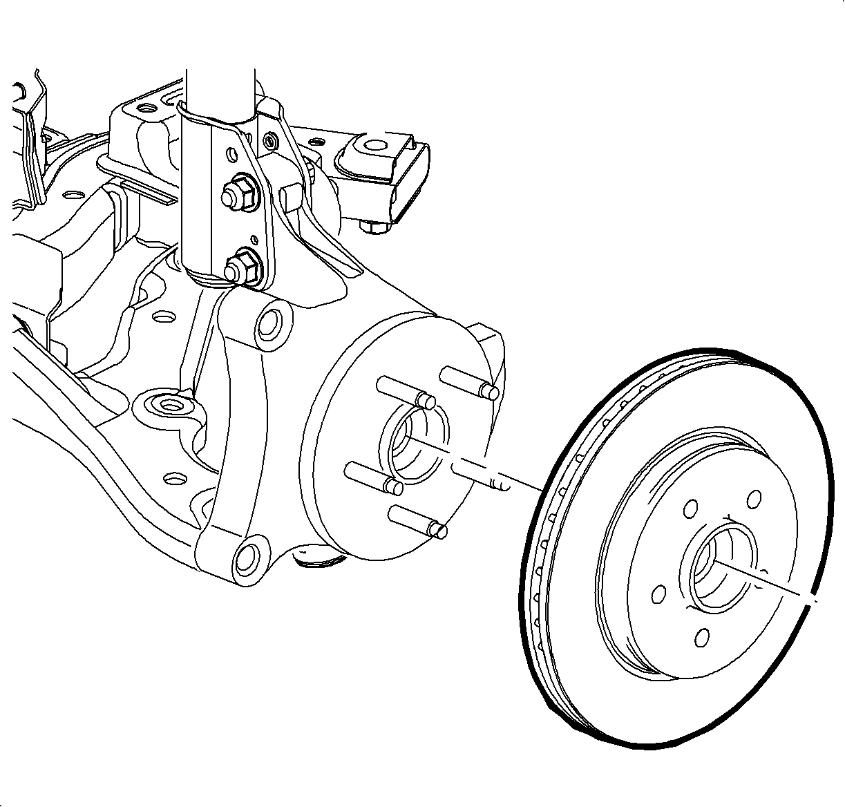
- Remove the front brake rotor. Refer to Front Brake Rotor Replacement.
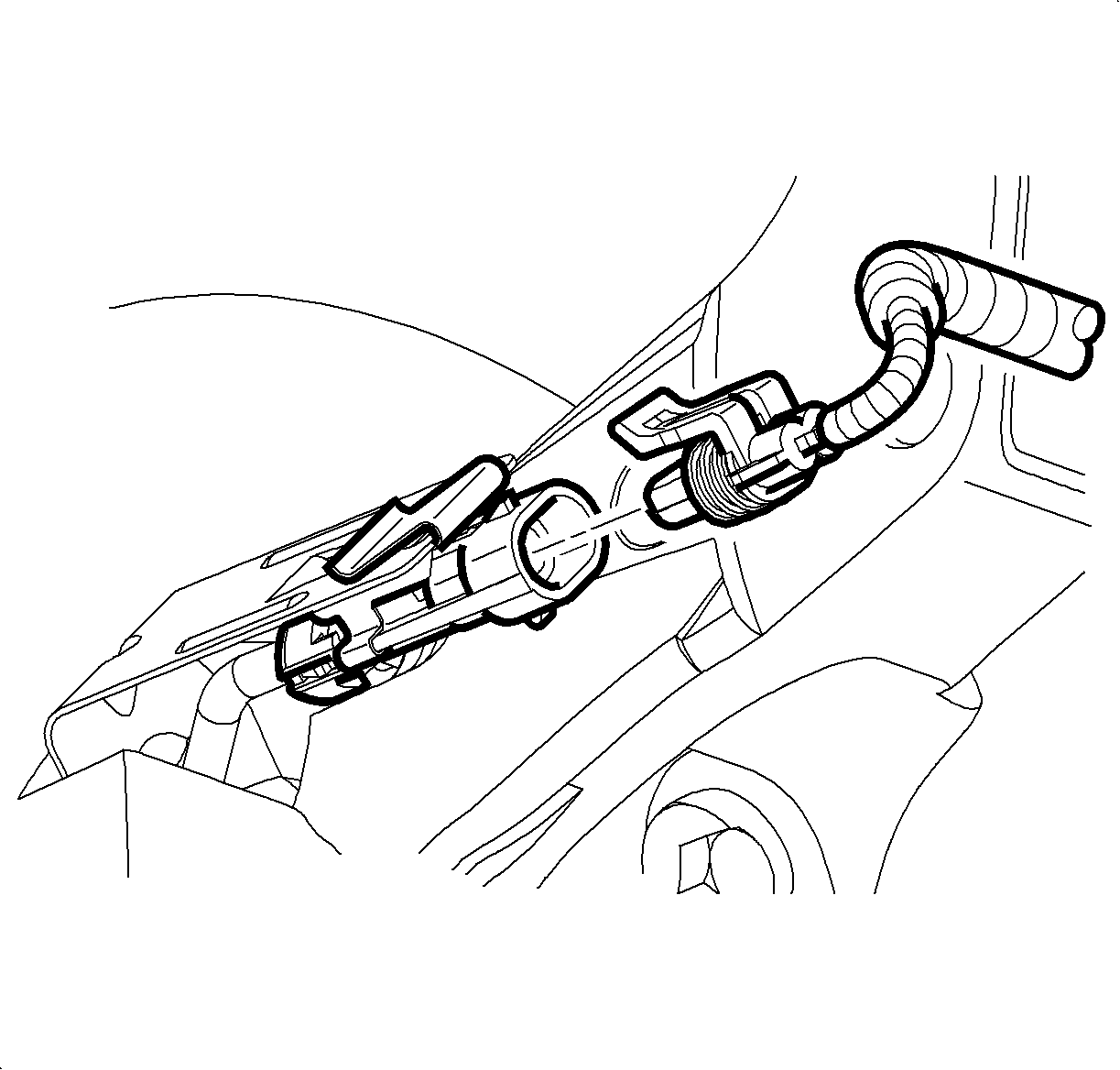
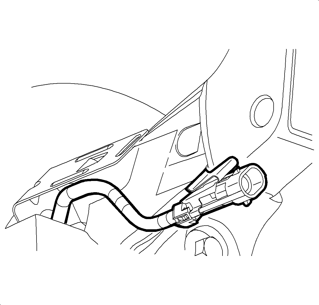
- Disconnect the wheel speed sensor electrical connector, if equipped.
- Remove the wheel speed sensor electrical connector from the connector bracket.
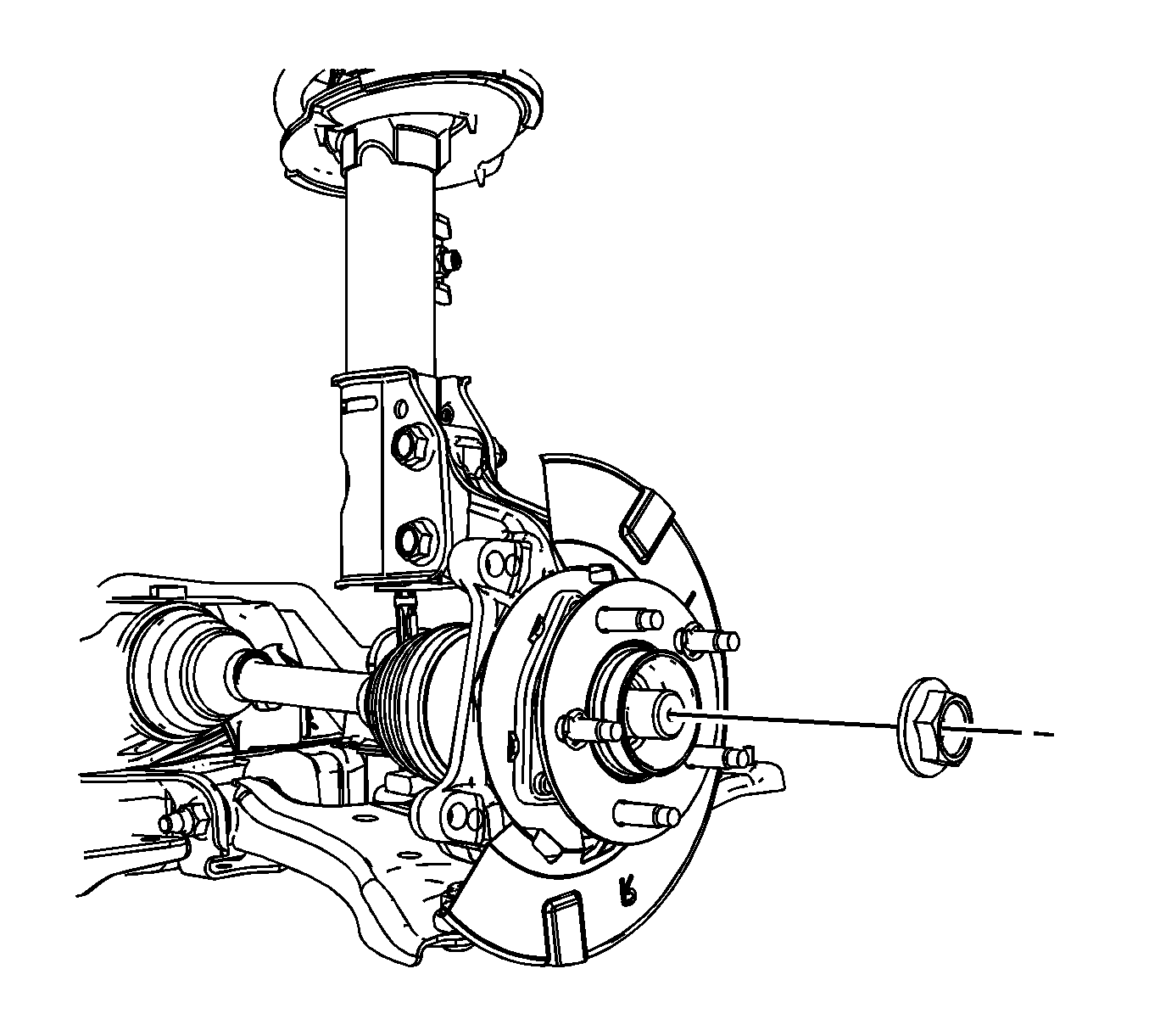
- Remove the front wheel drive shaft spindle nut.
- Remove the speed sensor. Refer to Front Wheel Speed Sensor Replacement.
- Support the wheel drive shaft with heavy mechanic's wire or equivalent.
- Remove and discard the wheel bearing/hub mounting bolts.
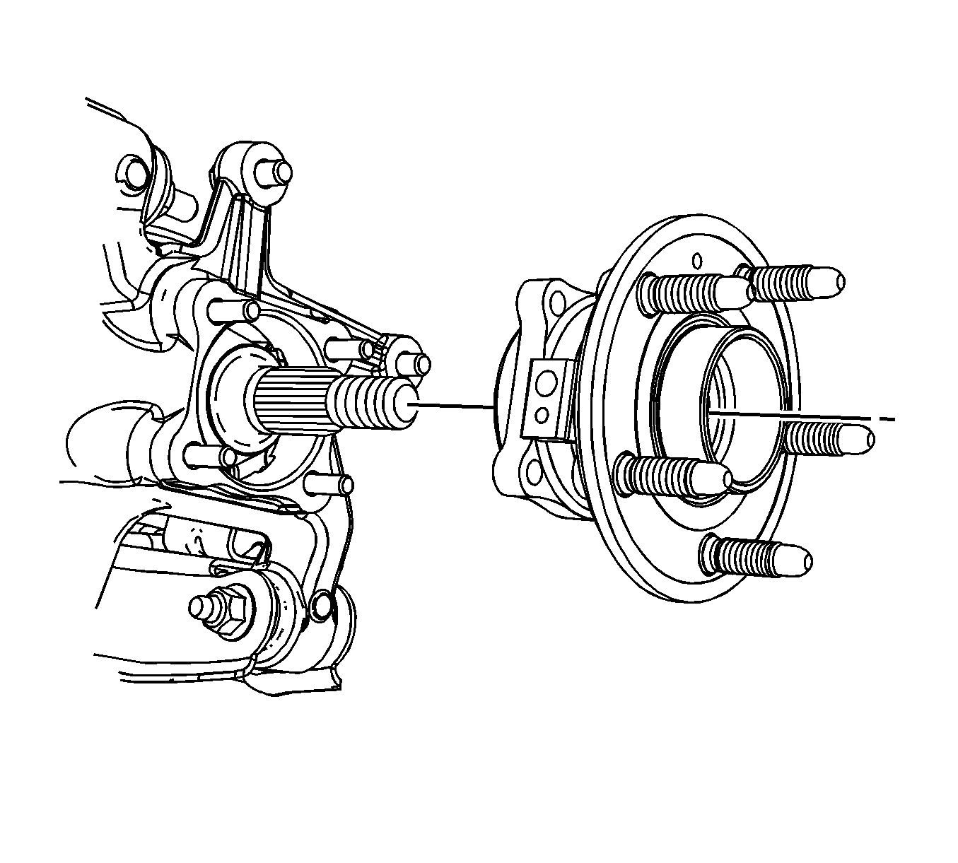
- Remove the wheel bearing/hub assembly from the steering knuckle.
Installation Procedure
- Install the wheel bearing/hub assembly to the steering knuckle.
- Clean the threads of the bolts with the proper cleaner.
- Apply threadlocker GM P/N 89021297 (Canadian P/N 10953488) on 2/3 of the bolts threads.
- Install the wheel bearing/hub mounting bolts.
- Install the wheel drive shaft spindle nut.
- Install the wheel speed sensor electrical connector to the mounting bracket, if equipped.
- Connect the wheel speed sensor electrical connector.
- Install the speed sensor. Refer to Front Wheel Speed Sensor Replacement.
- Install the front brake rotor. Refer to Front Brake Rotor Replacement.

Important: Allow the threadlocker to set for 10 minutes before using.
Notice: Refer to Fastener Notice in the Preface section.
Tighten
Tighten the bolts to 130 N·m (96 lb ft).

Tighten
Tighten the nut to 205 N·m (151 lb ft).


