For 1990-2009 cars only
Special Tools
| • | J 38868 Output Shaft Assembly Remover and Installer |
| • | J 6125-1B Slide Hammer with Adapter |
Removal Procedure
- Raise and support the vehicle. Refer to Lifting and Jacking the Vehicle.
- Drain the transfer case fluid. Refer to Transfer Case Fluid Replacement.
- Remove the propeller shaft. Refer to Propeller Shaft Replacement.
- Remove the right wheel drive shaft. Refer to Front Wheel Drive Shaft Replacement.
- Remove the intermediate shaft. Refer to Intermediate Shaft Replacement.
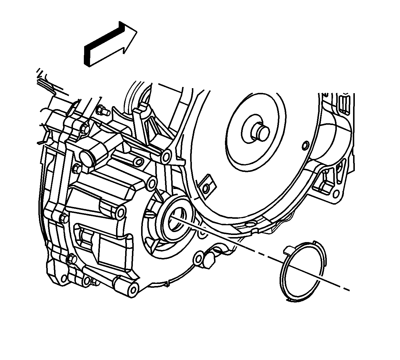
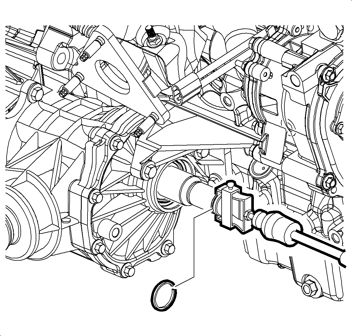
- Remove the retainer ring from the stub shaft for tool installation. Discard the used retainer ring.
- Remove the stub shaft using the J 6125-1B and J 38868 .
- Remove the transfer case mounting bracket. Refer to Transfer Case Bracket Replacement.
- Disconnect the transfer case vent hose.
- Support the transaxle with a jackstand.
- Remove the 4 bolts securing the transfer case to the transaxle.
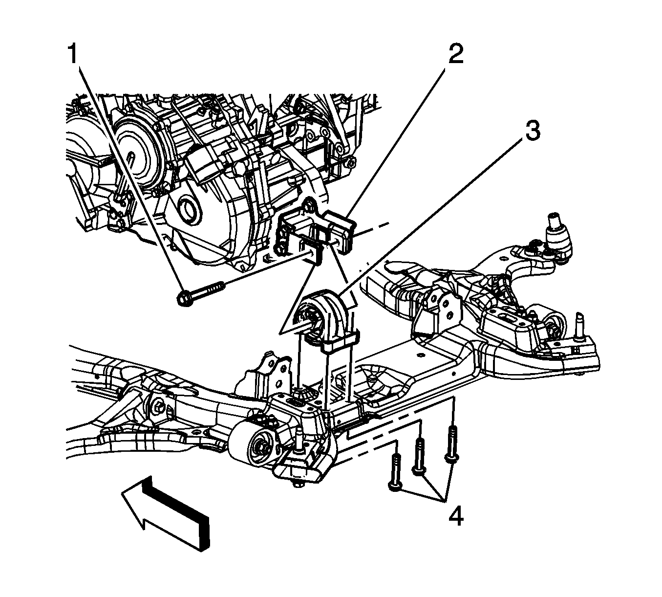
- Remove the 3 bolts (4) securing the rear transaxle mount (3) to the vehicle frame.
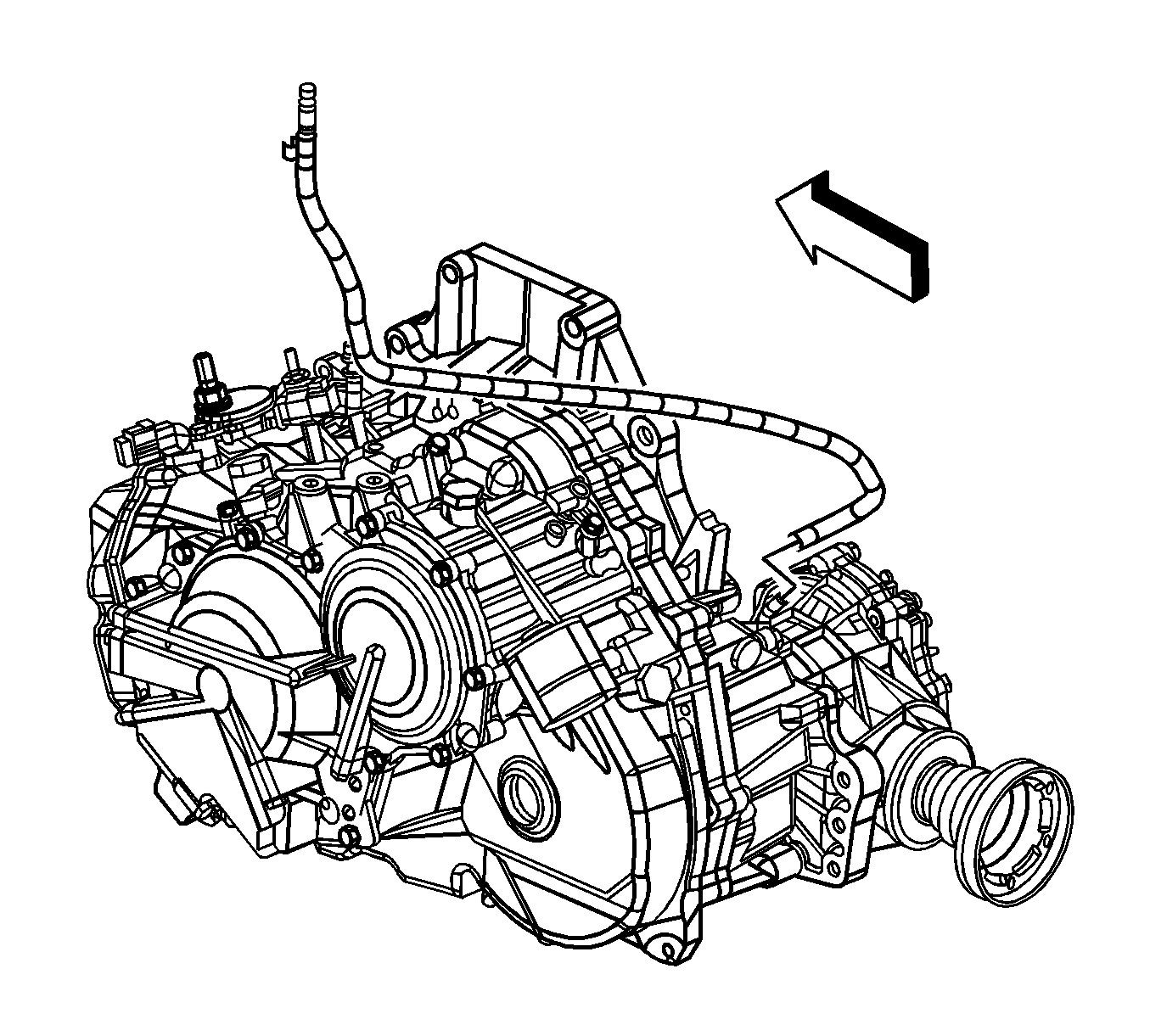
- Slide the transfer case away from the transaxle.
- Rotate the transfer case so that the propeller shaft drive flange faces the transaxle.
- Lift and rotate the transfer case so that the propeller shaft drive flange is pointing down toward the floor.
- Lower the transfer case through the opening between the engine oil pan and the vehicle frame.
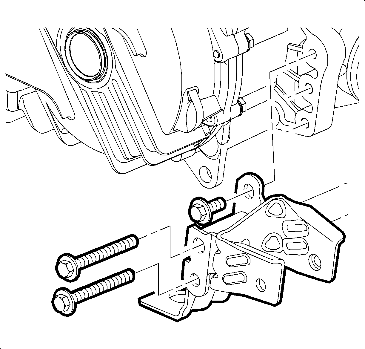
- Remove the 3 bolts and rear transaxle mount from the transfer case.
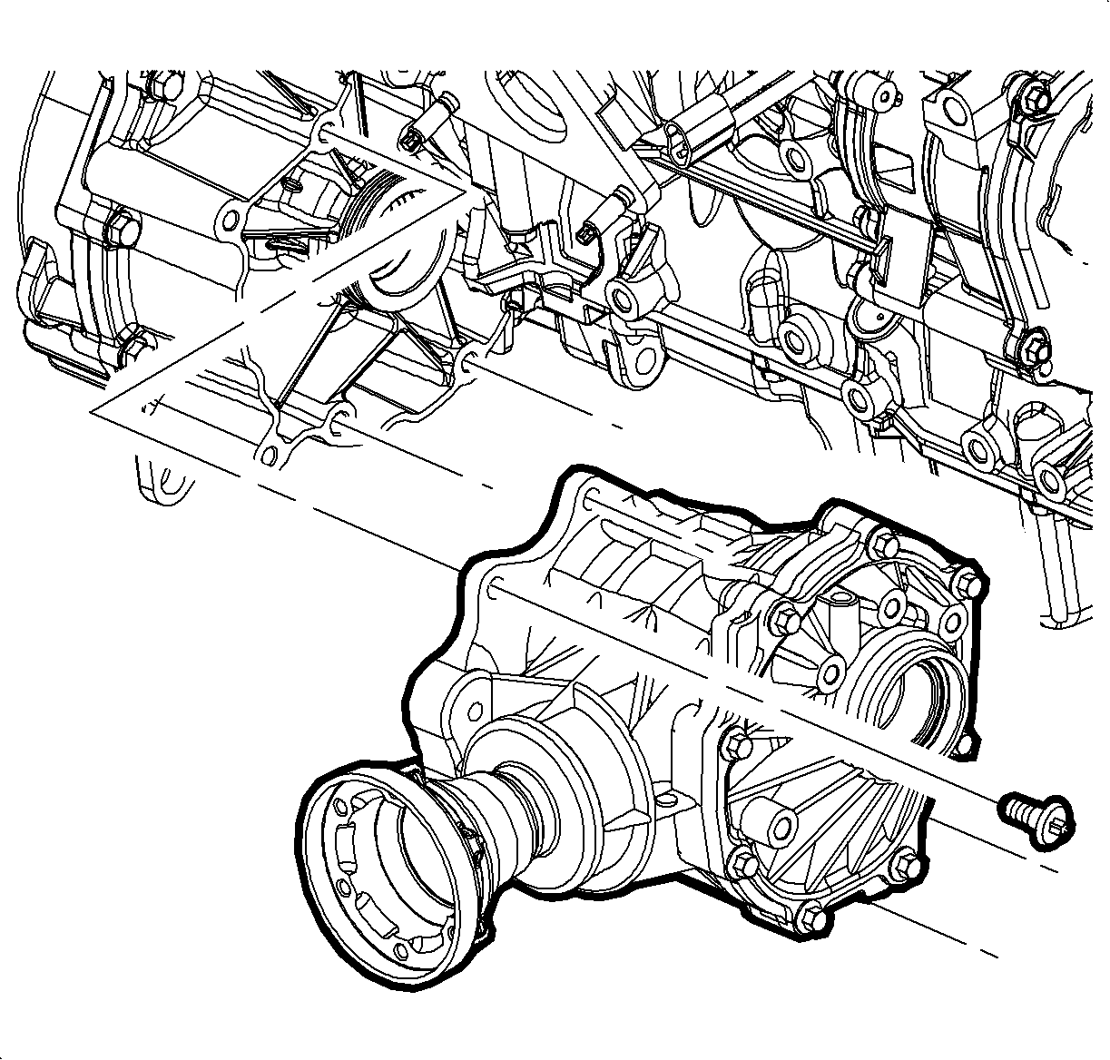
Note: Remove the rear transaxle mount from the transfer case after the transfer case has been removed from the vehicle.
Installation Procedure
- Install the rear transaxle mount to the transfer case.
- Install the 3 bolts securing the rear transaxle mount to the transfer case and tighten to 110 N·m (81 lb ft).
- Ensure the torque converter cover is in the proper location.
- With the transfer case propeller shaft drive flange pointing down toward the floor, lift the transfer case up between the engine oil pan and the vehicle frame.
- Rotate and align the transfer case with the transaxle.
- Install the 4 bolts securing the transfer case to the transaxle and tighten to 60 N·m (44 lb ft).
- Install the 3 bolts (4) securing the rear transaxle mount (3) to the vehicle frame and tighten to 50 N·m (37 lb ft).
- Remove the jackstand supporting the transaxle.
- Connect the transfer case vent hose.
- Install the transfer case mounting bracket. Refer to Transfer Case Bracket Replacement.
- Install the stub shaft using the J 6125-1B and J 38868 .
- Install a NEW retainer ring on the stub shaft.
- Install the intermediate shaft. Refer to Intermediate Shaft Replacement.
- Install the right wheel drive shaft. Refer to Front Wheel Drive Shaft Replacement.
- Fill the transfer case with fluid. Refer to Transfer Case Fluid Replacement.
- Lower the vehicle.

Caution: Refer to Fastener Caution in the Preface section.
