For 1990-2009 cars only
Special Tools
J-42188-B Ball Joint Separator
Removal Procedure
- Raise and support the vehicle. Refer to Lifting and Jacking the Vehicle.
- Remove the tire and wheel. Refer to Tire and Wheel Removal and Installation.
- Remove the wheel bearing/hub assembly. Refer to Front Wheel Bearing and Hub Replacement.
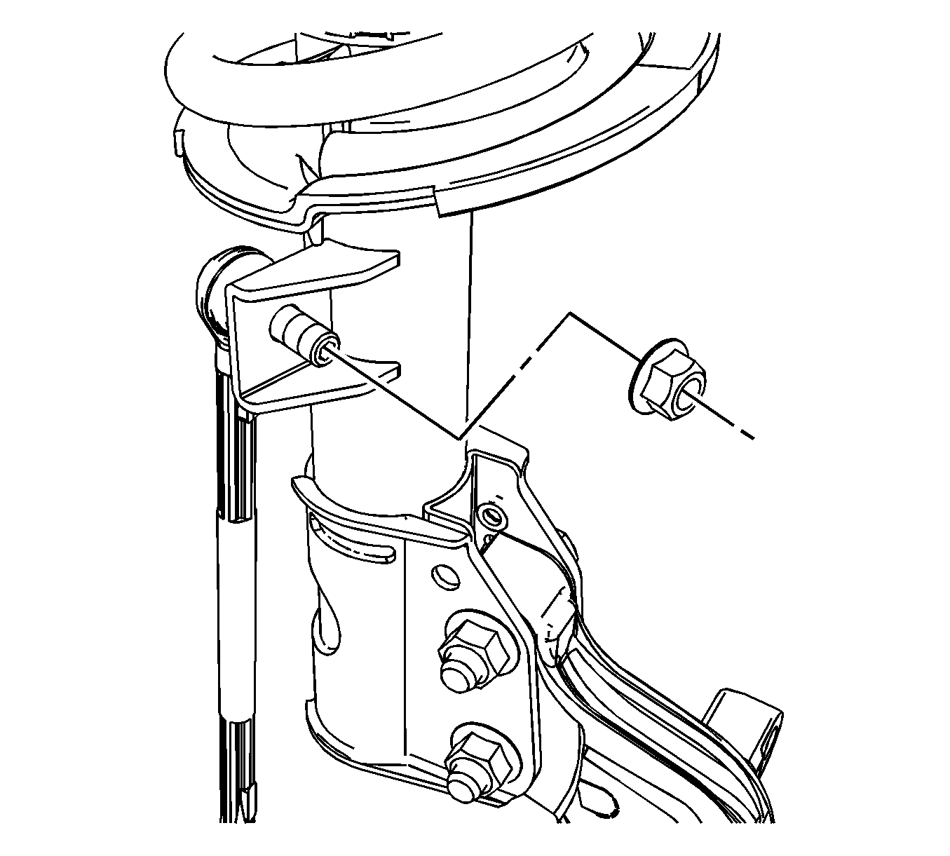
- Remove the nut and separate the stabilizer link from the strut assembly.
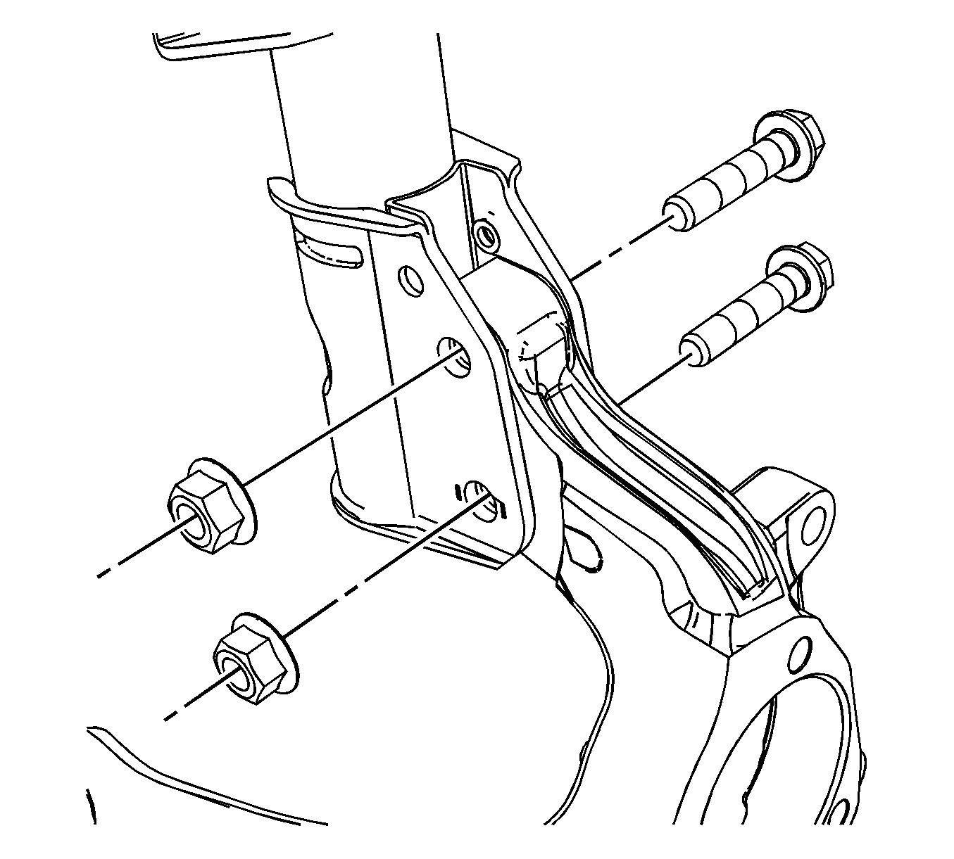
- Loosen the steering knuckle to strut bolts and nuts.
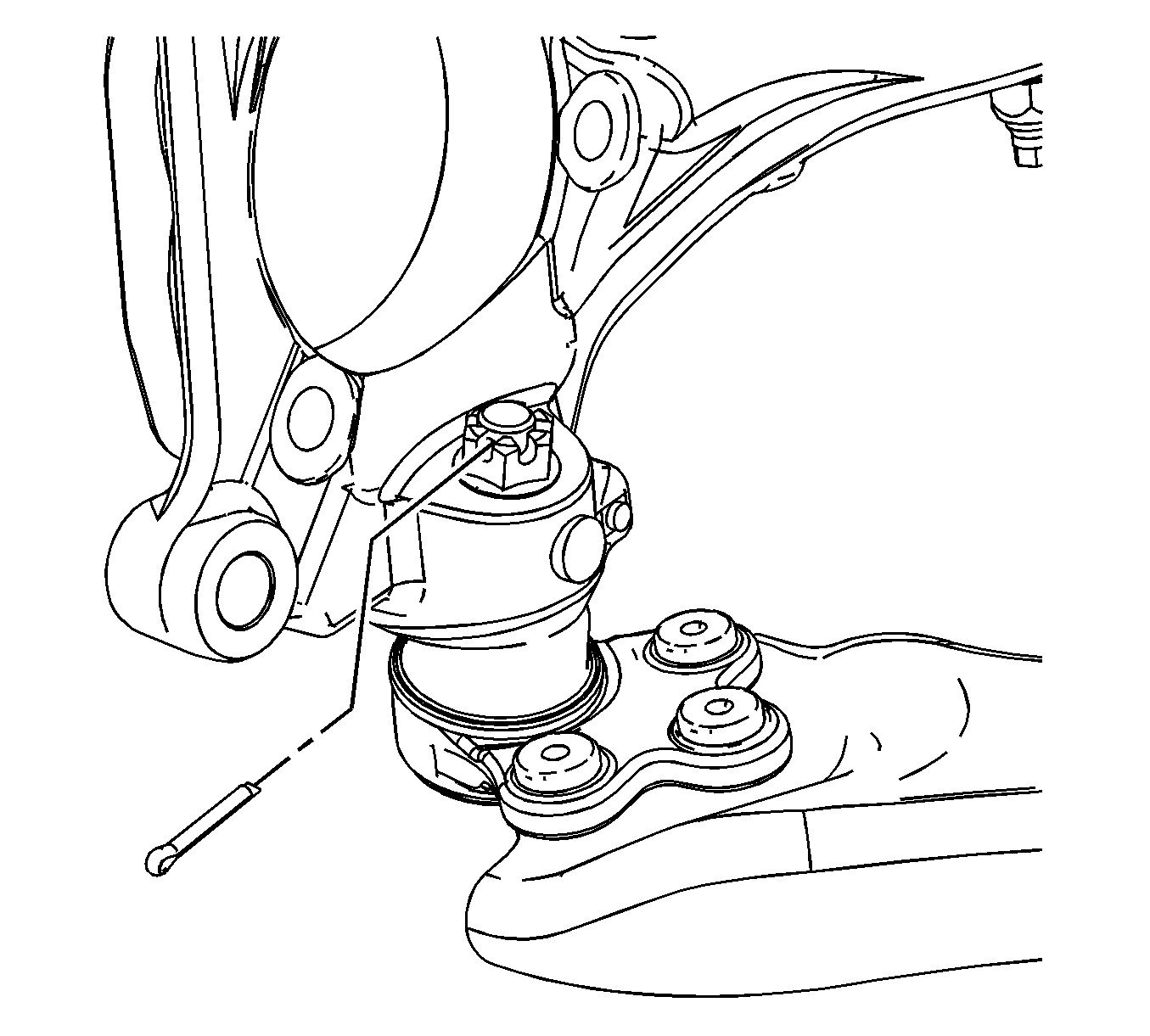
- Remove and discard the lower ball joint cotter pin.
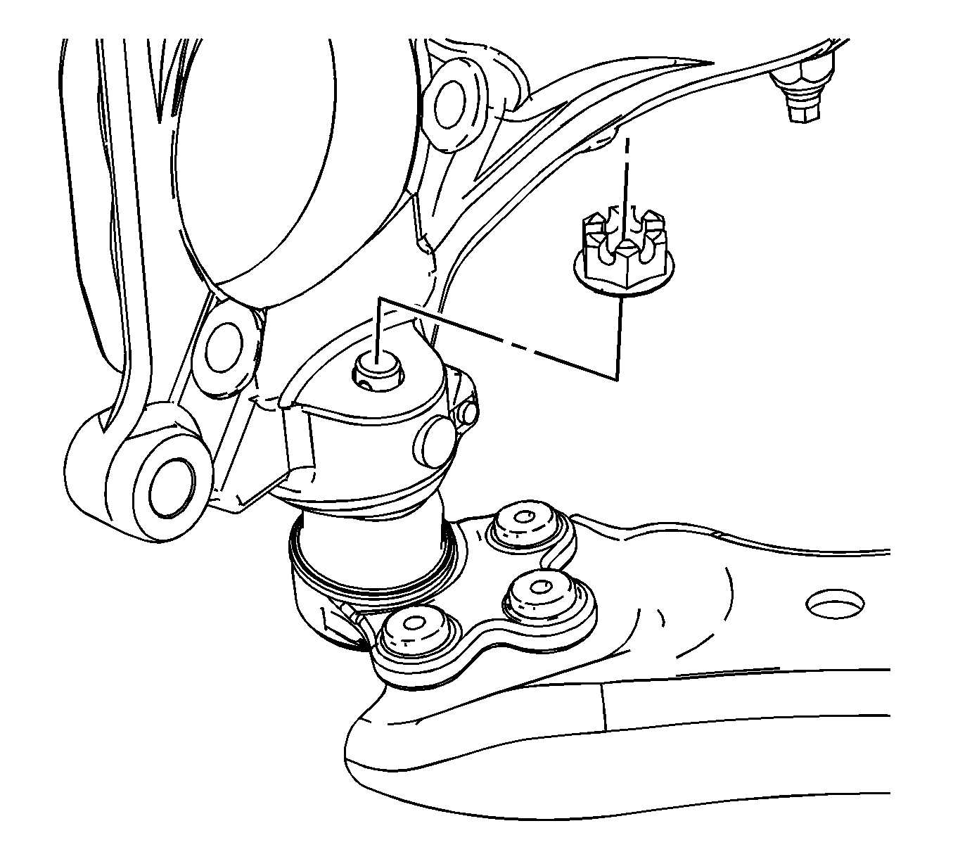
- Loosen the ball stud nut, until level with the top of the ball stud.
- Using the J-42188-B , separate the lower ball joint from the steering knuckle.
- Remove the lower ball joint nut and separate from the knuckle.
- Remove the outer tie rod end from the knuckle. Refer to Steering Linkage Outer Tie Rod Replacement.
- Remove the steering knuckle to strut bolts and nuts.
- Remove the steering knuckle from the vehicle.

Note: Do not allow the stabilizer link ball stud to rotate while removing the link nut.


Caution: Do not free the ball stud by using a pickle fork or a wedge-type tool. Damage to the seal or bushing may result.

Installation Procedure
- Position the steering knuckle to strut assembly.
- Loosely install the strut to steering knuckle bolts and nuts.
- Position the lower ball joint stud into the steering knuckle.
- Install the ball stud nut and tighten to 40 N·m (30 lb ft).
- Tighten the strut to steering knuckle bolts and nuts to 180 N·m (133 lb ft).
- Tighten the castle nut enough to allow for cotter pin installation.
- Install a new cotter pin.
- Install the outer tie rod end to the knuckle. Refer to Steering Linkage Outer Tie Rod Replacement.
- Position the stabilizer shaft link to the strut assembly and install the nut.
- Install the wheel bearing/hub assembly. Refer to Front Wheel Bearing and Hub Replacement.
- Install the tire and wheel. Refer to Tire and Wheel Removal and Installation.
- Lower the vehicle.
- Perform a wheel alignment. Refer to Wheel Alignment Measurement.


Caution: Refer to Fastener Caution in the Preface section.

Note: Do not loosen the castle nut for cotter pin installation.
Note: The cotter pin must not contact the wheel speed sensor or drive axle.

Note: Do not allow the stabilizer link ball stud to rotate while installing the link nut.
Tighten the nut to 65 N·m (48 lb ft).
