For 1990-2009 cars only
Frame Replacement LNJ
Special Tools
J 43828 Ball Joint Remover
Removal Procedure
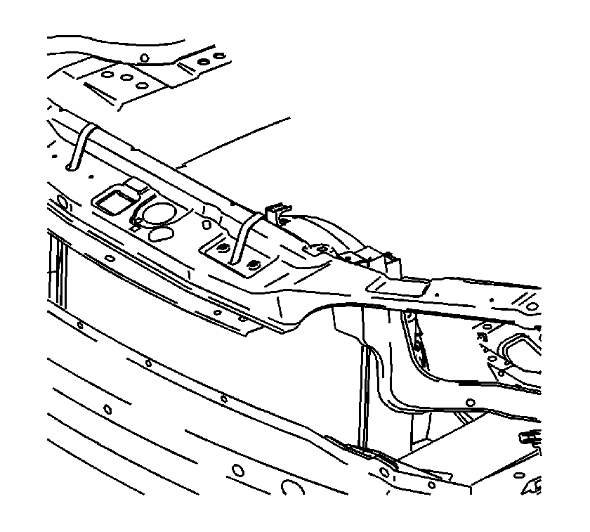
- Secure the radiator to the upper radiator support.
- Raise and support the vehicle. Refer to Lifting and Jacking the Vehicle.
- Remove the front wheels. Refer to Tire and Wheel Removal and Installation.
- Remove the side splash shield-to-frame fasteners.
- Remove the front air dam-to-frame fasteners.
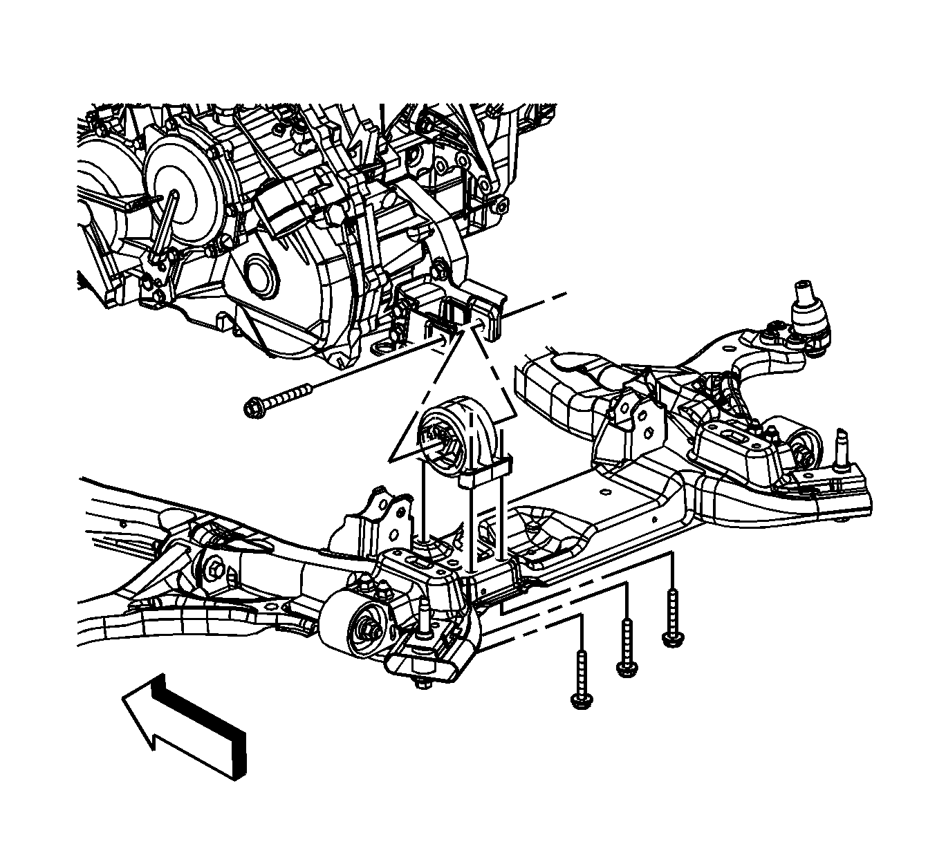
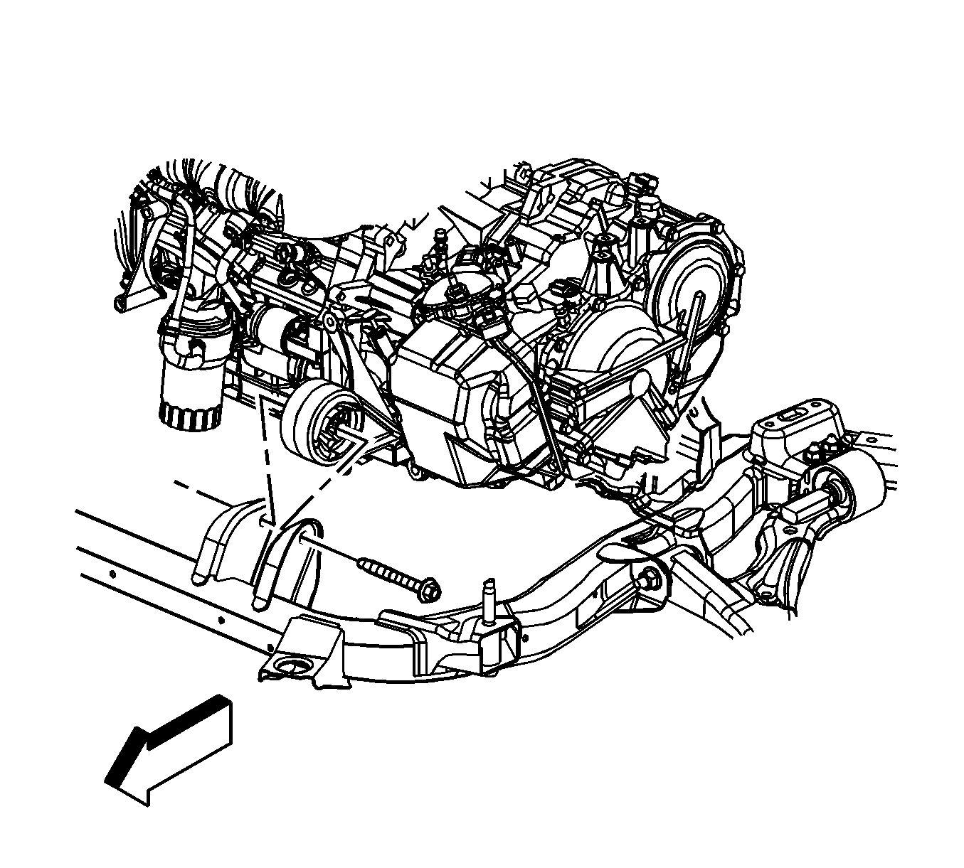
- Remove the rear transaxle mount-to-frame bolts.
- Remove the front transaxle mount through bolt.
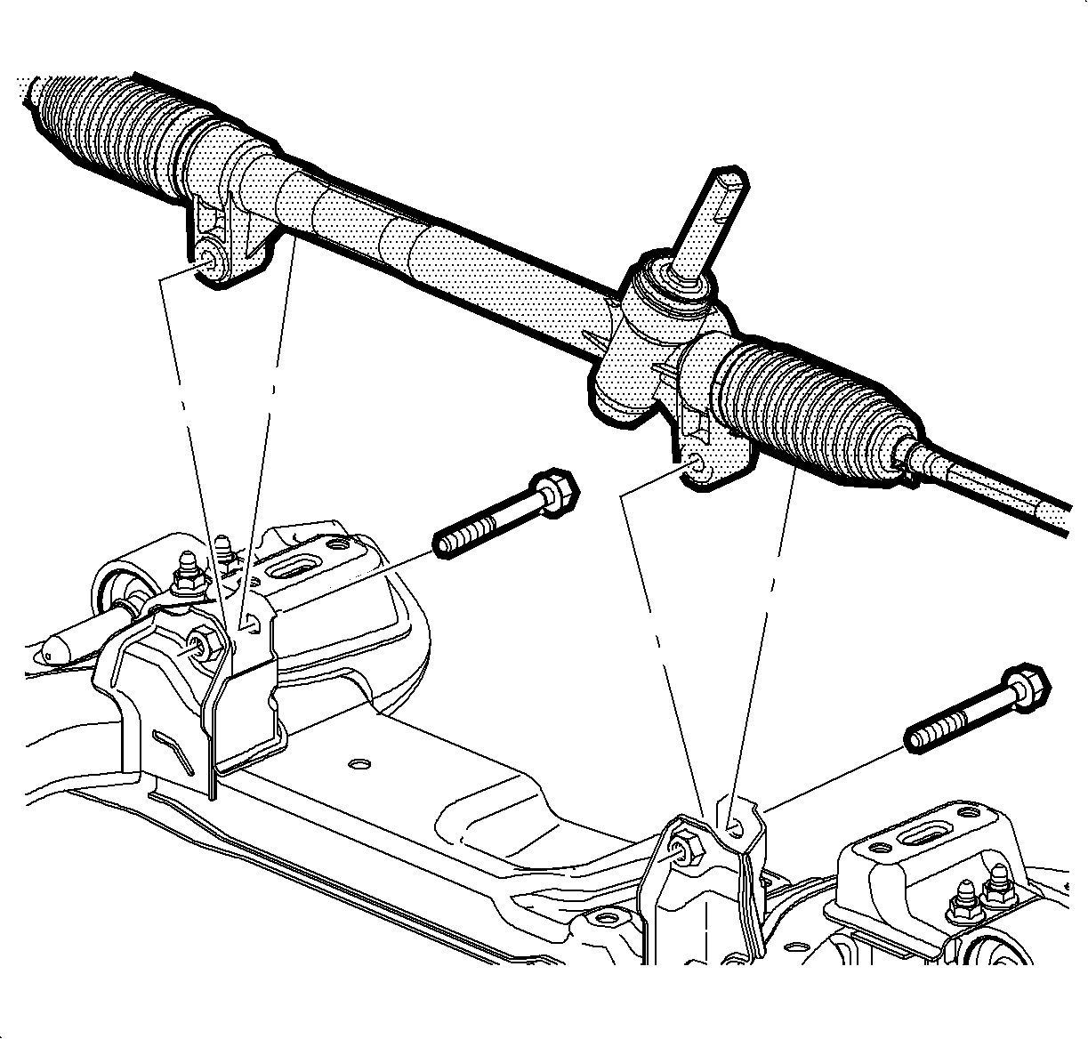
- Remove the steering gear-to-frame bolts.
- Using mechanics wire, secure the steering gear to the exhaust.
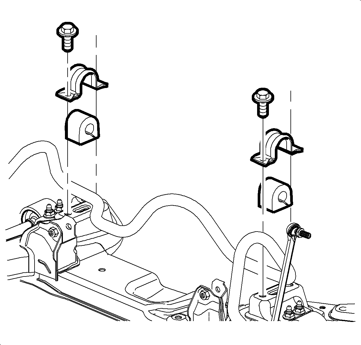
- Remove the stabilizer shaft clamp-to-frame bolts.
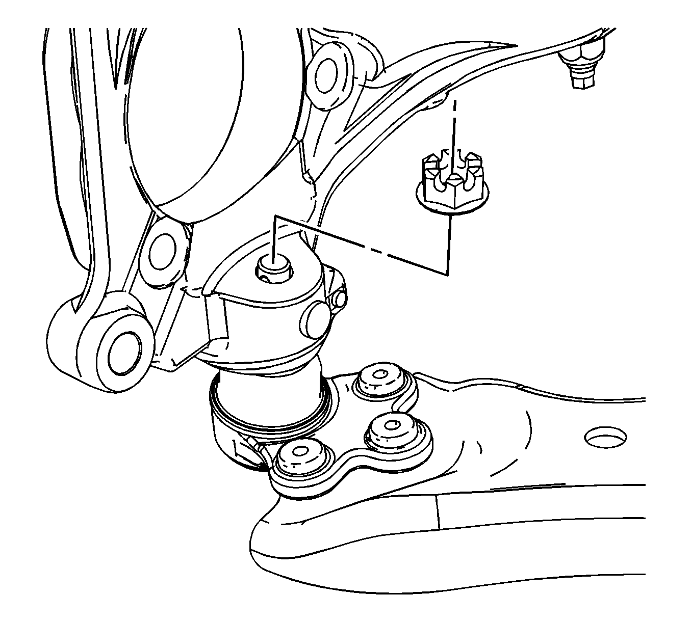
- Remove the lower ball joint cotter pins. Discard the cotter pins.
- Loosen the lower ball joint castle nut until the nut is level with the top of the ball stud.
- Using the J 43828 , separate the lower control arm from the steering knuckle.
- Remove the frame-to-body bolts. Discard the bolts.
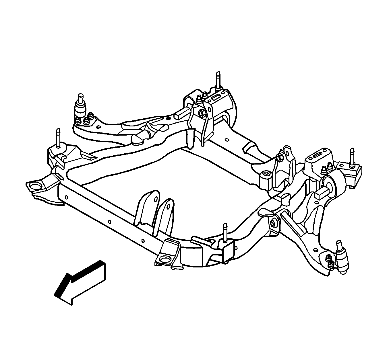
- Carefully lower the frame from the vehicle.
- Remove the lower control arms. Refer to Lower Control Arm Replacement.
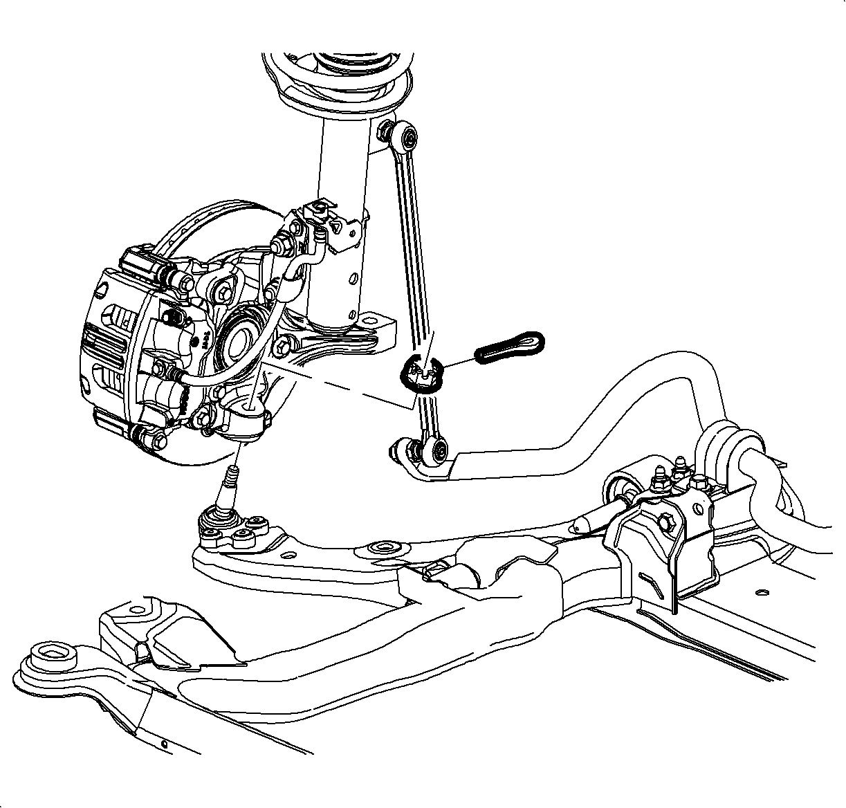
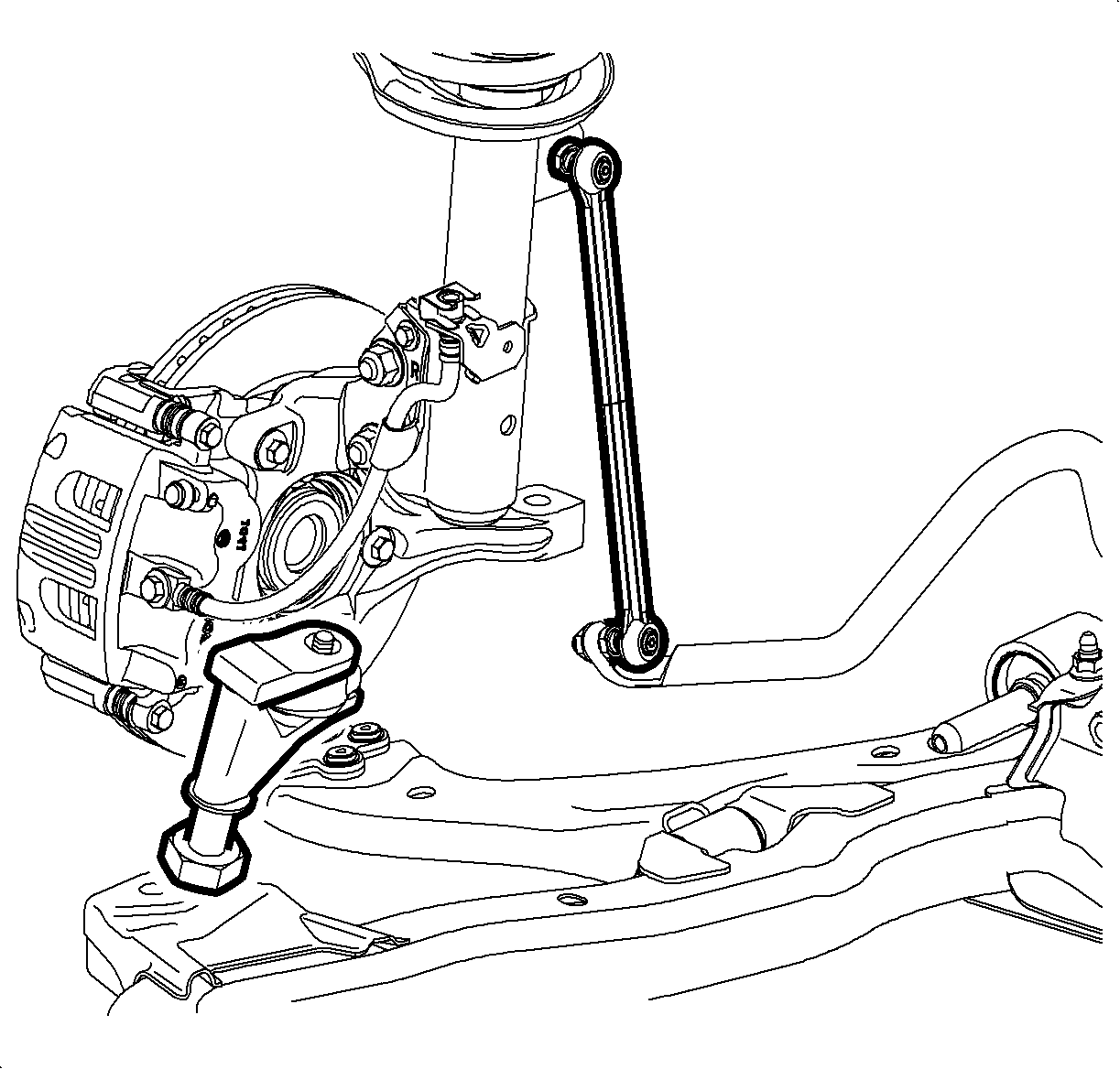
Caution: Do not free the ball stud by using a pickle fork or a wedge-type tool. Damage to the seal or bushing may result.
Installation Procedure
- Install the lower control arms. Refer to Lower Control Arm Replacement.
- Raise the frame to the body.
- Loosely install new frame-to-body bolts.
- Connect the ball joint stud to the steering knuckle.
- Install the ball stud castle nut and tighten to 40 N·m (30 lb in).
- Continue to tighten the castle nut to align the slots with the opening in the ball stud and install the ball stud cotter pin.
- Remove the mechanics wire and install the steering gear to the frame. Tighten the bolts to 110 N·m (81 lb ft).
- Install the front transaxle mount through bolt and tighten to 110 N·m (81 lb ft).
- Install the rear transaxle mount-to-frame bolts and tighten to 50 N·m (37 lb ft).
- Install the stabilizer shaft clamp and tighten the bolts to 50 N·m (37 lb ft).
- Tighten the frame-to-body bolts to 155 N·m (114 lb ft).
- Install the front air dam fasteners.
- Install the side splash shield-to-frame fasteners.
- Install the front wheels. Refer to Tire and Wheel Removal and Installation.
- Lower the vehicle.
- Release the radiator from the upper radiator support.
- Align the front suspension. Refer to Wheel Alignment - Steering Wheel Angle and/or Front Toe Adjustment.

Note: Do not tighten the fasteners at this time.
Caution: Refer to Fastener Caution in the Preface section.
Note:
• Do not loosen the castle nut in order to align the cotter pin slots. • Ensure the cutter pin ends do not contact the wheel speed sensor harness.


Frame Replacement LY7
Special Tools
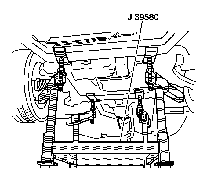
J 39580 Engine Support Table
Removal Procedure
- Secure the radiator, air conditioning condenser, and fan module assembly to the upper tie bar to keep the assembly with the vehicle when the frame is removed.
- Install the engine support fixture. Refer to Engine Support Fixture.
- Raise and support the vehicle. Refer to Lifting and Jacking the Vehicle.
- Remove the tire and wheel assemblies. Refer to Tire and Wheel Removal and Installation.
- Remove the engine splash shields. Refer to Engine Splash Shield Replacement.
- Remove the catalytic converters. Refer to Catalytic Converter Replacement - Left Side and Catalytic Converter Replacement - Right Side.
- Remove the propeller shaft if the vehicle is equipped with AWD. Refer to Propeller Shaft Replacement.
- Remove both left and right stabilizer shaft insulator clamps. Refer to Stabilizer Shaft Insulator Replacement.
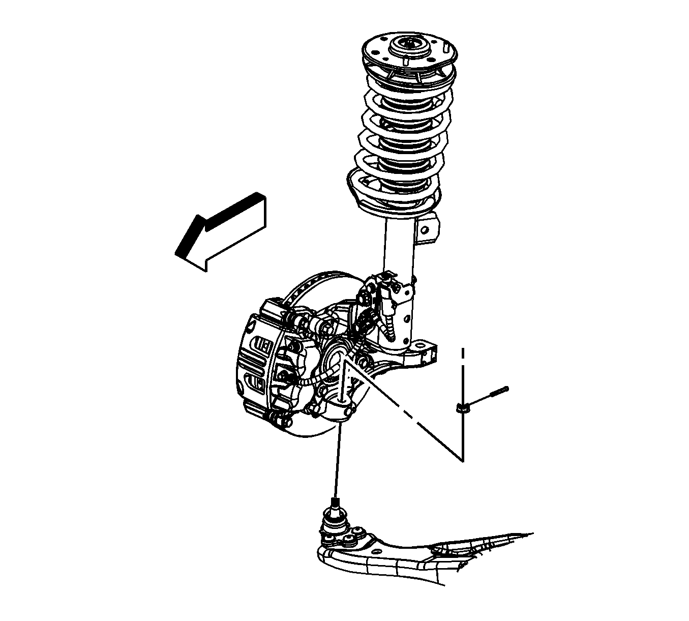
- Remove the lower ball joints from the steering knuckles. Refer to Lower Control Arm Replacement.
- Disconnect the intermediate steering shaft from the steering gear. Refer to Intermediate Steering Shaft Replacement.
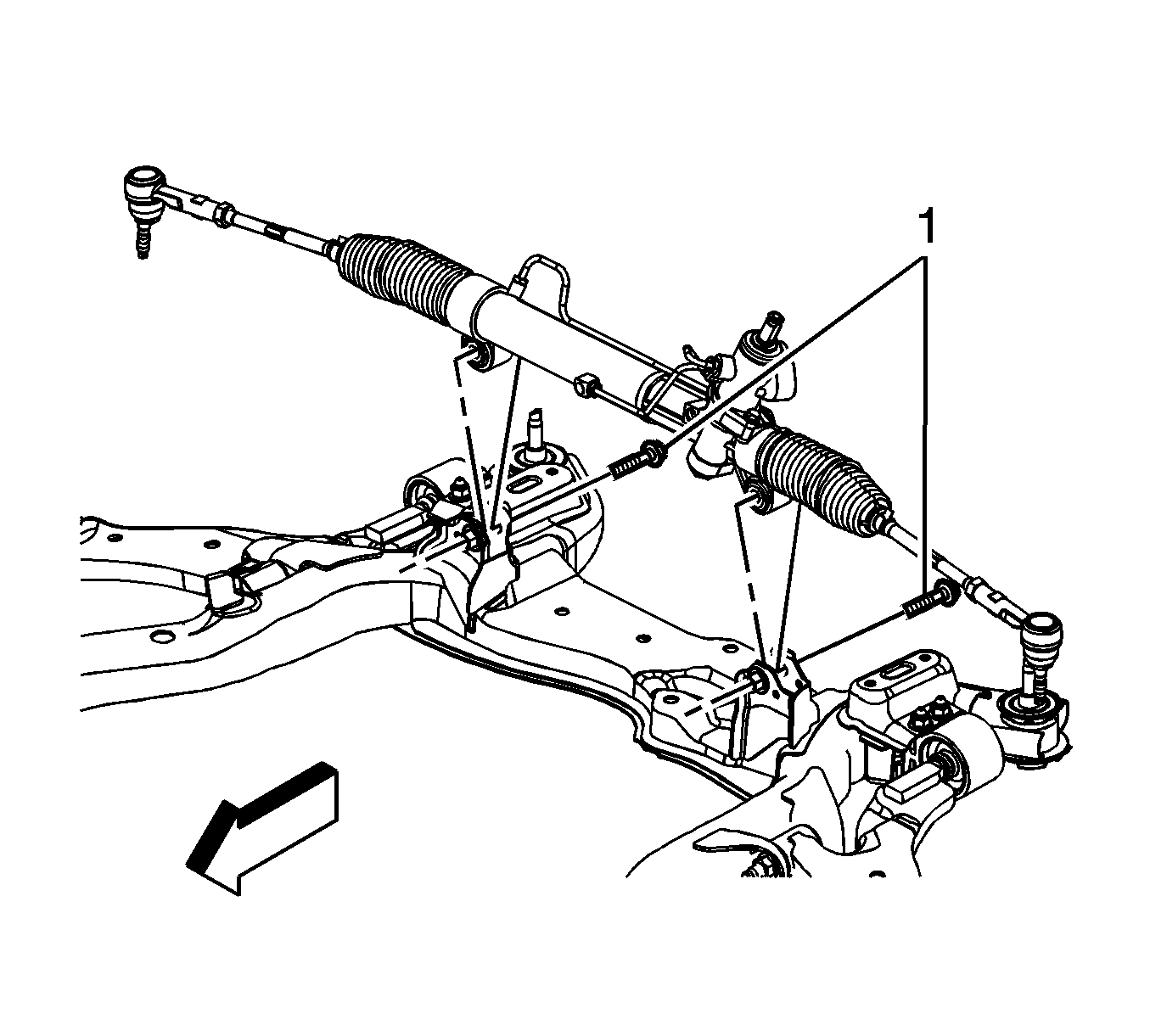
- Remove the power steering gear mounting bolts (1) and secure the gear out of the way using mechanics wire or equivalent. Refer to Steering Gear Replacement.
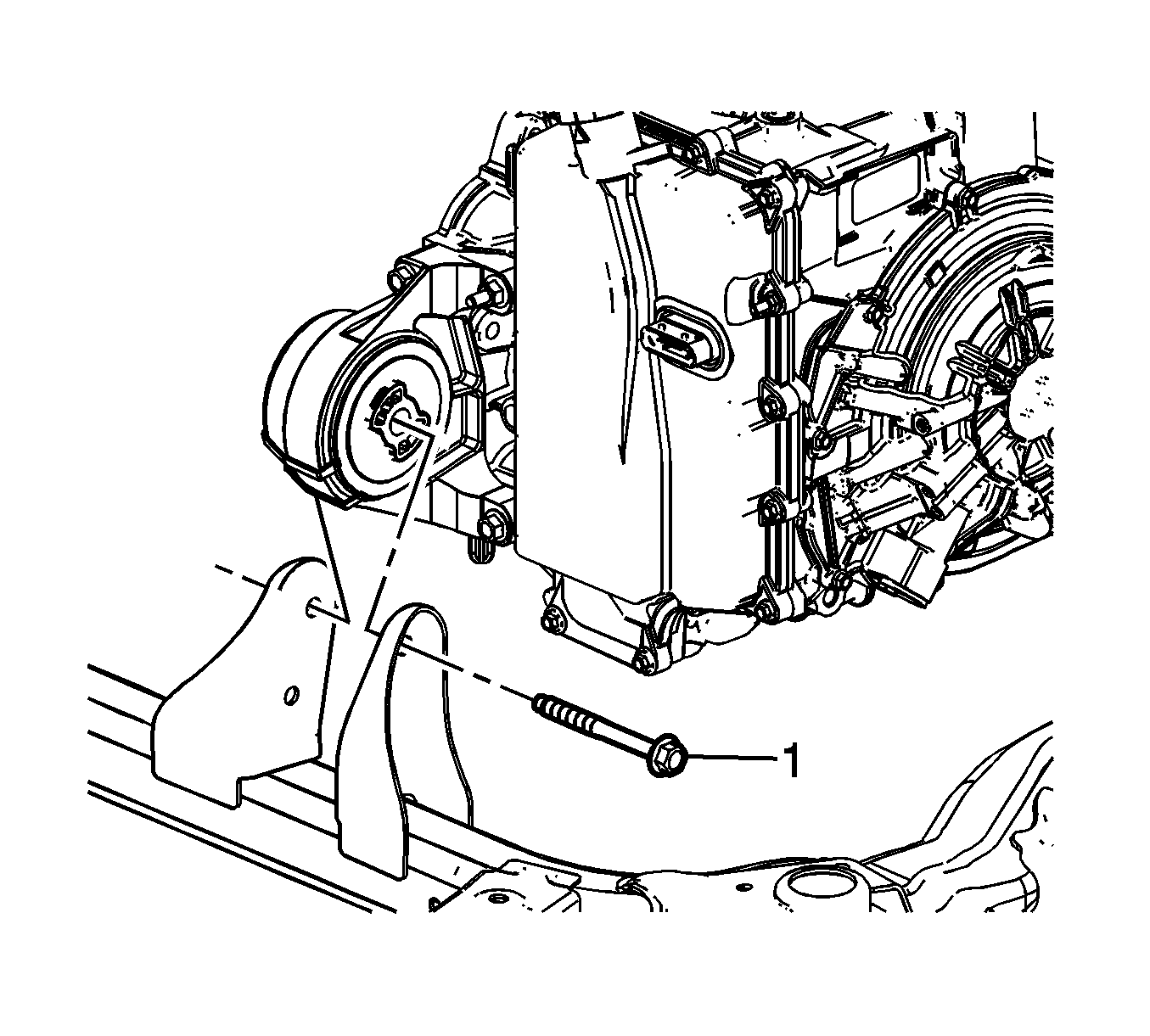
- Remove the front transmission mount thru bolt (1).
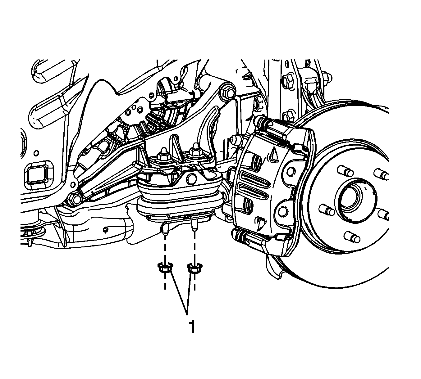
- Remove the left transmission mount lower nuts (1).
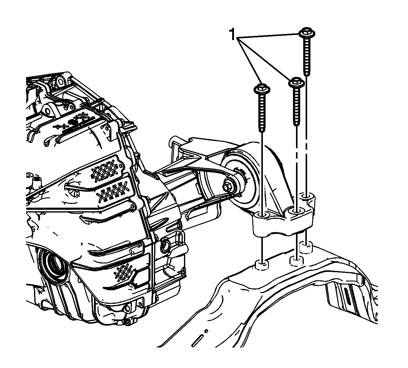
- Remove the rear transmission mount to frame bolts (1).
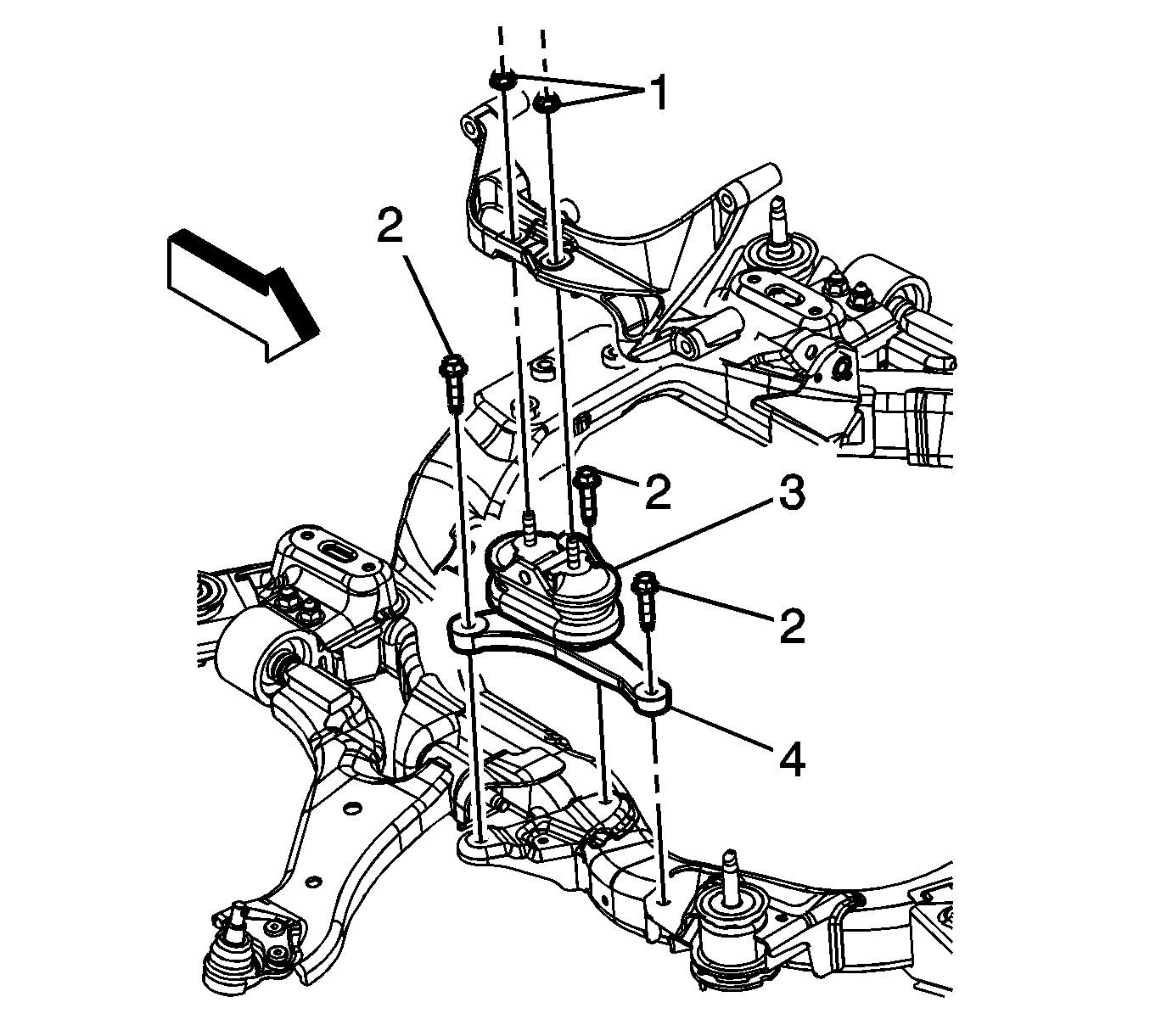
- Remove the lower engine mount bracket to frame bolts (2).
- Lower the vehicle until the frame contacts the J 39580 .
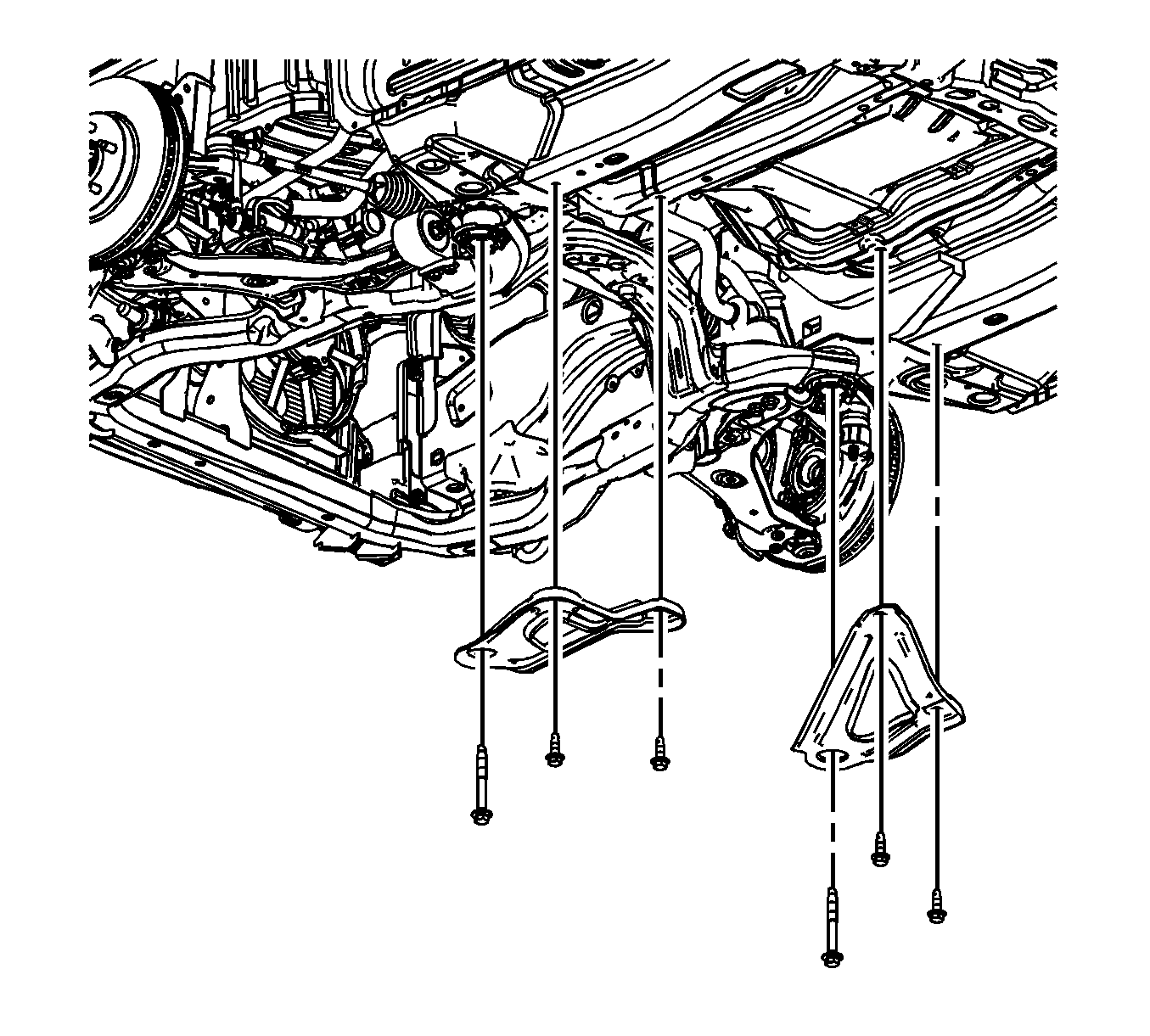
- Remove the frame reinforcements. Refer to Drivetrain and Front Suspension Frame Reinforcement Replacement.
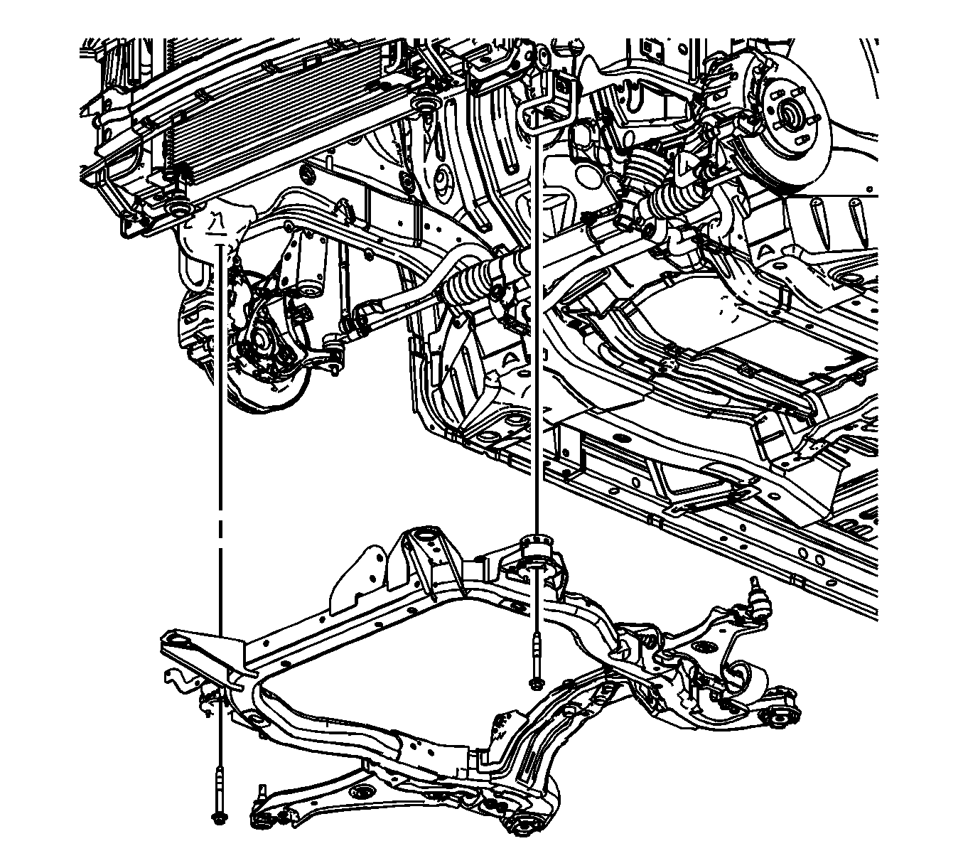
- Remove the front frame bolts.
- Raise the vehicle off of the frame.
- If replacing the frame, remove the lower control arms. Refer to Lower Control Arm Replacement.

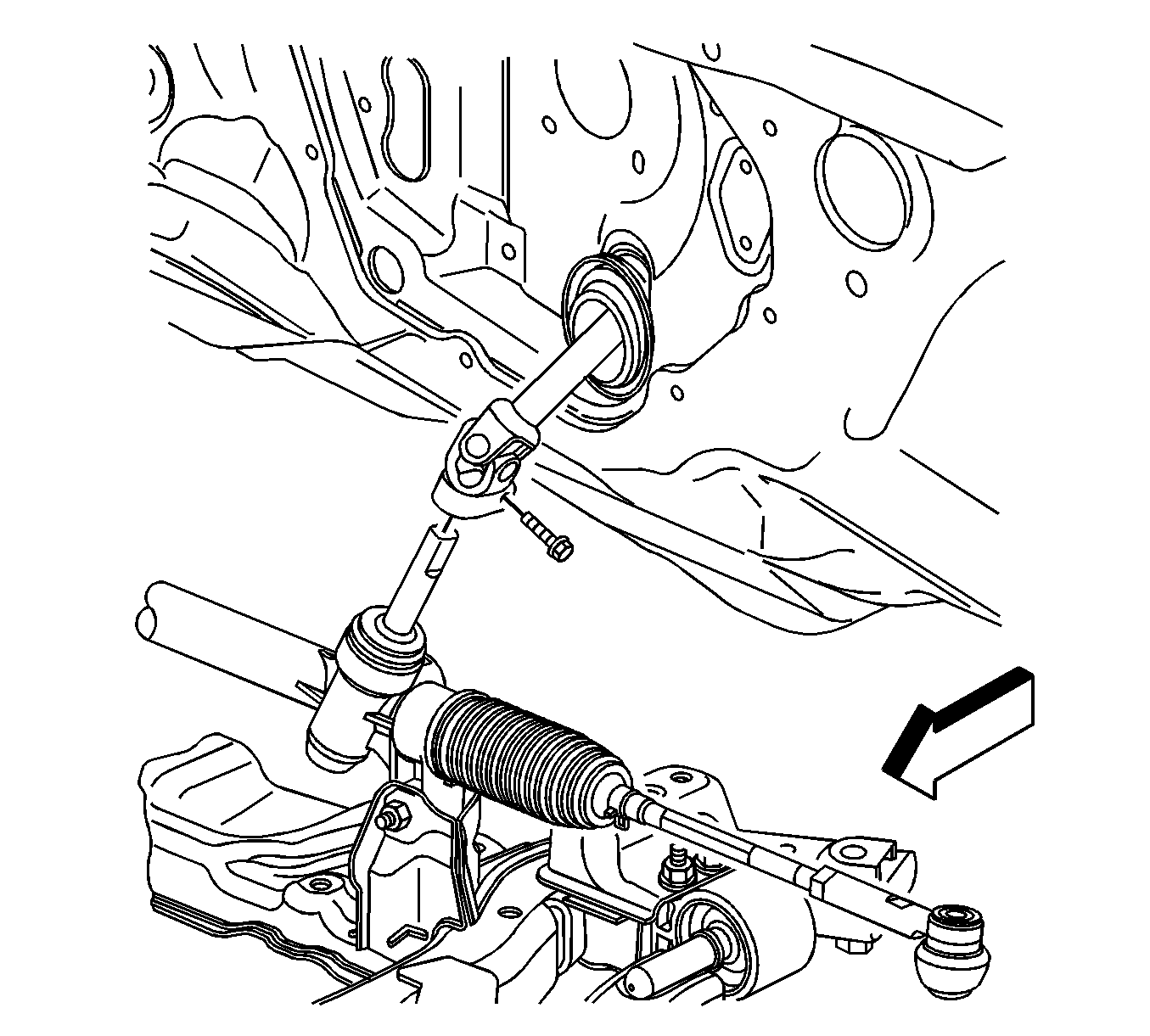
Note: Whenever the steering gear is moved in relation to the body, disconnect the intermediate shaft from the steering gear.
Installation Procedure
- If removed, install the lower control arms. Refer to Lower Control Arm Replacement.
- Lower the vehicle on to the frame.
- Install the front frame bolts and tighten to 155 N·m (114 lb ft).
- Install the frame reinforcement. Refer to Drivetrain and Front Suspension Frame Reinforcement Replacement.
- Raise the vehicle off of the J 39580 .
- Install the lower engine mount bracket to frame bolts (2) and tighten to 50 N·m (37 lb ft).
- Install the rear transmission mount to frame bolts (1) and tighten to 50 N·m (37 lb ft).
- Install the left transmission mount lower nuts (1) and tighten to 50 N·m (37 lb ft).
- Install the front transmission mount thru bolt (1) and tighten to 110 N·m (81 lb ft).
- Install the power steering gear mounting bolts (1). Refer to Steering Gear Replacement.
- Install the intermediate steering shaft to the steering gear. Refer to Intermediate Steering Shaft Replacement.
- Install the lower ball joints to the steering knuckles. Refer to Lower Control Arm Replacement.
- Install the propeller shaft if the vehicle is equipped with AWD. Refer to Propeller Shaft Replacement.
- Install the catalytic converters. Refer to Catalytic Converter Replacement - Left Side and Catalytic Converter Replacement - Right Side.
- Install both left and right stabilizer shaft insulator clamps. Refer to Stabilizer Shaft Insulator Replacement.
- Install the engine splash shields. Refer to Engine Splash Shield Replacement.
- Install the tire and wheel assemblies. Refer to Tire and Wheel Removal and Installation.
- Remove the engine support fixture. Refer to Engine Support Fixture.
- Release the radiator, air conditioning condenser, and fan module assembly from the upper tie bar.
- Check the wheel alignment. Refer to Wheel Alignment Measurement.

Caution: Refer to Fastener Caution in the Preface section.


