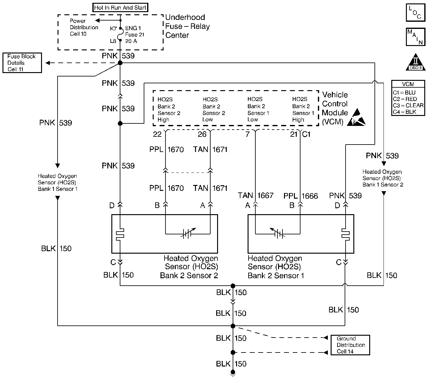
Circuit Description
This diagnostic test is designed in order to measure the efficiency of the three-way catalytic converter (TWC) system. Catalytic convertor efficiency is a measure of its ability to store oxygen after converting the levels of hydrocarbon (HC), carbon monoxide (CO), and oxides of nitrogen (NOx) to less harmful gases. The control module is able to evaluate the catalyst efficiency once the vehicle has met the enable criteria and the vehicle is at idle instead of the steady cruise speeds used in the past.
Once the conditions for running this diagnostic trouble code (DTC) are met, the control module commands either a lean or rich air/fuel ratio depending on the current state of the exhaust oxygen level. The control module issues a rich command if the exhaust is currently lean, or a lean command if the exhaust is currently rich. After completion of the first command, a second and opposite command is issued.
For example, if the control module were to command a rich mixture, the upstream heated oxygen sensor (HO2S) voltage would increase immediately. The rich mixture is delayed in reaching the downstream HO2S due to the conversion process occurring within the converter. The higher the efficiency, the more the delay before the rich or lean mixture is detected by the downstream oxygen (O2) sensor. As a result of the lower conversion efficiency within a damaged or poisoned catalyst, the delay in the rich or lean mixture reaching the downstream O2 sensor is significantly shorter. This DTC monitors the amount of time required for both the upstream and downstream HO2S voltages to cross a calibrated voltage threshold in response to the rich or lean command.
Conditions for Running the DTC
| • | No active VS sensor DTCs |
| • | No active TP sensor DTCs |
| • | No active HO2S DTCs |
| • | No active MAF sensor DTCs |
| • | No active IAT sensor DTCs |
| • | No active fuel trim DTCs |
| • | No active misfire DTCs |
| • | The system is in closed loop. |
| • | The command air/fuel ratio is 14.7:1. |
| • | The air flow is greater than 15 g/s but less than 50 g/s. |
| • | Any change in engine load is less than 10 %. |
| • | The vehicle speed is between 20-85 mph. |
| • | The vehicle speed is greater than 0 mph with the scan tool installed. |
| • | The engine speed is less than 4,700 RPM. |
| • | The throttle position is greater than 2 %. |
| • | The predicted catalyst temperature is greater than 450°C(840°F). |
| • | The IAT is greater than -9°C(16°F). |
| • | The ECT is greater than 75°C(167°F). |
Conditions for Setting the DTC
The VCM determines that the oxygen storage capacity of the catalyst has degraded below a calibrated threshold.
Action Taken When the DTC Sets
The VCM will turn ON the Malfunction Indicator Lamp (MIL).
Conditions for Clearing the MIL or DTC
| • | The control module turns OFF the MIL after 3 consecutive drive trips when the test has run and passed. |
| • | A history DTC will clear if no fault conditions have been detected for 40 warm-up cycles. A warm-up cycle occurs when the coolant temperature has risen 22°C (40°F) from the startup coolant temperature and the engine coolant reaches a temperature that is more than 70°C (158°F) during the same ignition cycle. |
| • | Use a scan tool in order to clear the DTCs. |
Diagnostic Aids
Difficulty running the OBD II status DTC P0430 test may be encountered in areas where test conditions cannot be maintained easily, especially in urban areas. To minimize the amount of driving required to complete the test, use the following procedure:
| • | Catalyst can be warmed up in service bay previous to drive cycle. |
| • | Engine also can be warmed up in bay. HO2S 2 activity test: Using a scan tool, monitor MAP, HO2S 1, and HO2S 2 displays in Park or Neutral above idle. Compare HO2S 1 and HO2S 2 activity (amplitude and frequency) to each other during a 30 second period. If HO2S 2 activity is nearly as great as HO2S 1 activity, a problem exists; use diagnostic table on facing page. If much less activity is noted, system is functioning properly. |
Test Description
Notice: In order to avoid damaging the replacement three-way catalytic converter, correct the engine misfire or mechanical fault before replacing the three-way catalytic converter.
The numbers below refer to the step numbers on the diagnostic table.
-
This table checks for conditions that can cause the three-way catalytic converter efficiency to appear degraded. Inspect and repair the exhaust system as necessary.
-
Before the three-way catalytic converter is replaced, make sure that the following conditions are not present.
| • | Misfire |
| • | High engine oil consumption or coolant consumption |
| • | Retarded spark timing or weak spark |
Step | Action | Value(s) | Yes | No | ||||||
|---|---|---|---|---|---|---|---|---|---|---|
1 |
Important: Before clearing the DTCs, use the scan tool Capture Info to save the Freeze Frame and the Failure Records for reference. The control module's data is deleted once the Clear Info function is used. Did you perform the Powertrain On-Board Diagnostic (OBD) System Check? | -- | ||||||||
2 | Are any DTCs set? | -- | Go to the applicable DTC table | |||||||
Did you find a problem? | -- | |||||||||
4 |
Did you find a problem? | -- | ||||||||
5 |
Does the scan tool indicate that the diagnostic Passed? | -- | System OK | |||||||
|
Important: Before replacing the catalytic converter refer to Test Descriptions. Replace the catalytic converter. Is the action complete? | -- | Go to the applicable DTC table | System OK |
