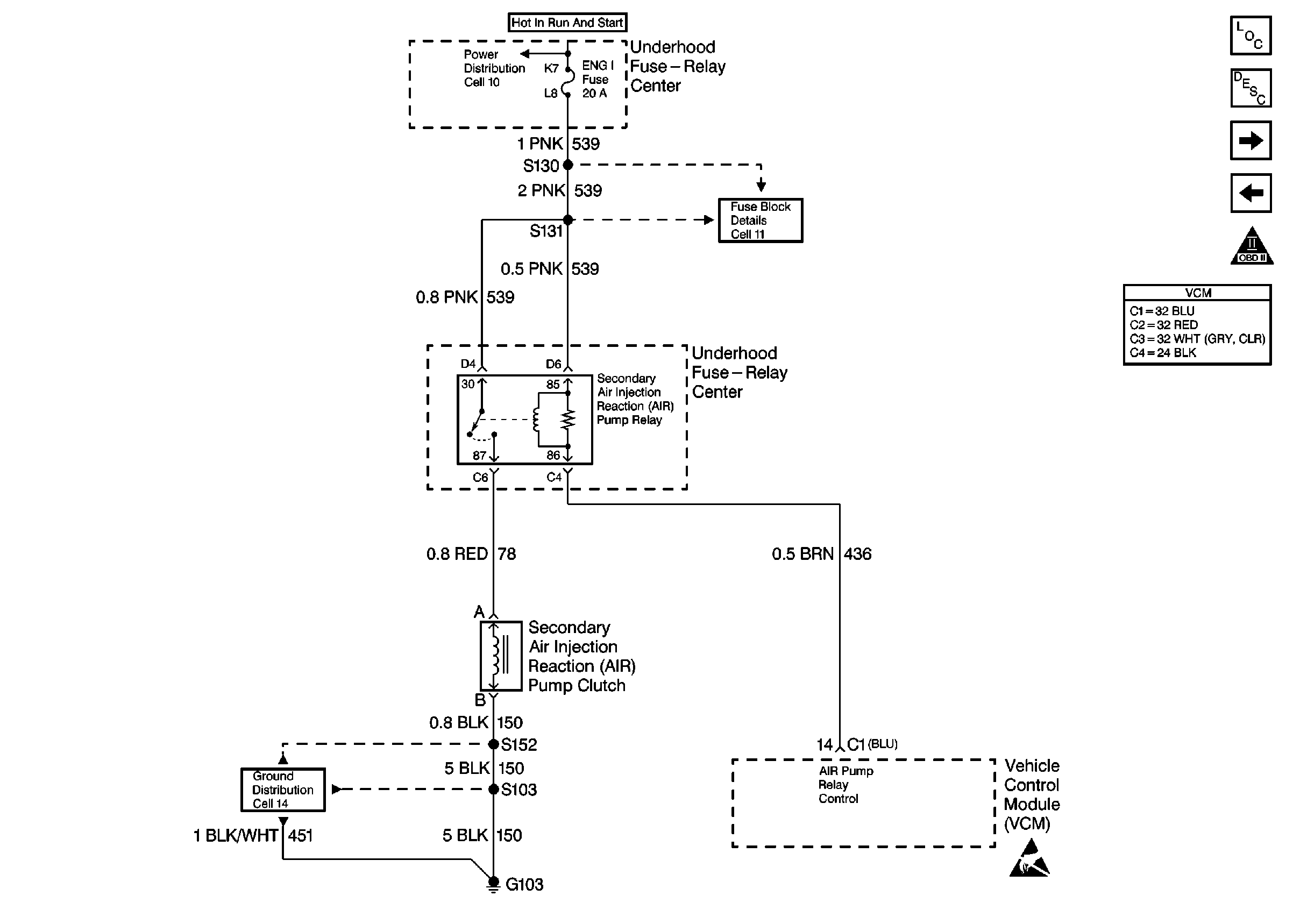
Refer to Engine Controls Schematics
Cell 23: Secondary AIR Controls
Circuit Description
A secondary air injection AIR pump is used on this vehicle to lower tailpipe emissions on start-up. The VCM supplies a ground to the AIR pump relay control circuit. This energizes the AIR pump relay and supplies voltage to the AIR pump clutch. The VCM uses the HO2S voltages and the short term fuel trim to diagnose the secondary air injection system.
The VCM monitors the HO2S voltages and the short term fuel trim value when the AIR pump is energized. This additional air causes the HO2S voltages to shift low, reflecting the leaner mixture. The short term fuel trim should increase above 128 confirming that the VCM is supplying additional fuel. The low HO2S voltages and higher short term fuel trim provide confirmation that the secondary air injection system is operating properly. When the AIR pump is de-energized, the HO2S voltages should increase and begin switching normally.
This DTC is set when the VCM determines that the HO2S voltages for both banks did not respond as expected during this test. If only one HO2S responded as expected, the VCM sets either a DTC P1415, or a P1416, depending upon which engine bank the AIR system is inoperative.
Conditions for Running the DTC
| • | No active secondary AIR DTCs |
| • | No active CMP sensor DTCs |
| • | No active ECT sensor DTCs |
| • | No active EGR DTCs |
| • | No active fuel trim DTCs |
| • | No active IAC DTCs |
| • | No active IAT sensor DTCs |
| • | No active MAF sensor DTCs |
| • | No active MAP sensor DTCs |
| • | No active HO2S DTCs |
| • | No active transmission DTCs |
| • | No active EVAP system DTCs |
| • | No active TP sensor DTCs |
| • | No active VS sensor DTCs |
| • | No active misfire DTCs |
| • | The commanded air/fuel ratio is 14.7:1. |
| • | The system voltage is greater than 10 volts |
| • | The engine speed is greater than 550 RPM. |
| • | The engine load is less than 50 %. |
| • | The MAF is less than 100 g/s. |
| • | The system has been in closed loop operation for more than 15 seconds. |
| • | The IAT is greater than 0°C(32°F). |
| • | The ECT is between 75°C-105°C(167°F-221°F). |
Conditions for Setting the DTC
The HO2S voltage remains above 299 mV or the change in the short term fuel trim value is less than a calibrated value.
Action Taken When the DTC Sets
| • | The VCM illuminates the MIL during the second consecutive drive cycle in which the diagnostic reports a fail. |
| • | The VCM will set the DTC and records the operating conditions at the time the diagnostic fails. The VCM stores the failure information in the scan tools Freeze Frame and Failure Records. |
Conditions for Clearing the MIL or DTC
| • | The control module turns OFF the MIL after 3 consecutive drive trips when the test has run and passed. |
| • | A history DTC will clear if no fault conditions have been detected for 40 warm-up cycles. A warm-up cycle occurs when the coolant temperature has risen 22°C (40°F) from the startup coolant temperature and the engine coolant reaches a temperature that is more than 70°C (158°F) during the same ignition cycle. |
| • | Use a scan tool in order to clear the DTCs. |
Diagnostic Aids
The AIR shut off valve is spring loaded and requires air pressure to open for air to flow. A leak in the hose between the AIR pump and the AIR shut off valve could cause a no flow condition even though the pump is flowing air.
A weak or worn AIR pump may flow air but may not be able to overcome the spring in the AIR shut off valve.
Low AIR system volume may cause a DTC P1415, a DTC P1416 or an intermittent complaint. Also check for the following conditions:
| • | Pinched, kinked, or restricted AIR pipes, hoses or fittings |
| • | Leaks, holes, loose fittings or hoses |
| • | Restricted or obstructed AIR pump inlet hose |
| • | Worn or loose AIR pump drive belts |
An AIR supply hose that is melted before the check valve could indicate exhaust gas back-flow past the check valve.
Test Description
The numbers below refer to the step numbers on the diagnostic table.
-
This step will determine if the AIR System is functioning correctly.
-
This step will determine if the VCM is capable of controlling the AIR Pump Relay.
-
This step is to check for a short to voltage on the control circuit.
-
This step will determine if the pump is capable of flowing air.
-
This step is to check for a weak or worn AIR Pump. If the pump is weak it could flow air but may not be able to overcome the Shut Off Valve. Refer to Diagnostic Aids.
-
This step is to ensure that no leaks are found in the hose between the AIR Pump and the AIR Shut Off Valve. The Shut Off Valve is spring loaded and requires air pressure to open for air to flow. A leak could prevent the valve from opening causing a no flow condition even though the pump is flowing air.
-
An open fuse for the ignition feed circuit could be caused by a short to ground in the components operated by the relay. Also check the wiring in the circuits on the switched side of the relay. Refer to Diagnostic Aids.
Step | Action | Value(s) | Yes | No | ||||||||||||
|---|---|---|---|---|---|---|---|---|---|---|---|---|---|---|---|---|
1 |
Important: Before clearing the DTCs, use the scan tool Capture Info to save the Freeze Frame and the Failure Records for reference. The control module's data is deleted once the Clear Info function is used. Did you perform the Powertrain On-Board Diagnostic (OBD) System Check? | -- | ||||||||||||||
Does the Short Term Fuel Trim indicate a change of more than the specified value within 30 seconds? | 16 % | |||||||||||||||
3 | The DTC is intermittent. Are any additional DTCs stored? | -- | Go to the applicable DTC table | Go to Diagnostic Aids | ||||||||||||
4 |
Is the AIR Pump clutch engaged? | -- | ||||||||||||||
5 |
Did you find a problem? | -- | ||||||||||||||
6 |
Is the test lamp ON? | -- | ||||||||||||||
7 |
Is the test lamp ON? | -- | ||||||||||||||
8 |
Did you find a problem? | -- | ||||||||||||||
9 | Check for an open in the AIR Pump clutch feed circuit between the relay and clutch. Did you find a problem? | -- | ||||||||||||||
10 |
Is the test lamp ON at both terminals? | -- | ||||||||||||||
Is the test lamp ON? | -- | |||||||||||||||
12 |
Did you find a problem? | -- | ||||||||||||||
13 | Check for an open in the AIR Pump Relay Control circuit between the relay and the VCM. Did you find a problem? | -- | ||||||||||||||
Is the test lamp ON? | -- | |||||||||||||||
15 |
Does air flow from the valve? | -- | ||||||||||||||
Does the air flow from the hose? | -- | |||||||||||||||
Does the air flow increase as the engine is accelerated? | 1500 RPM | |||||||||||||||
Check for leaks or loose hose connections on the hose between the AIR Pump and the AIR Shut Off Valve. Did you find a problem? | -- | |||||||||||||||
19 | Check for leaks or obstructions in the hose between the AIR Pump and the AIR Shut Off Valve. Did you find a problem? | -- | ||||||||||||||
20 | Check for leaks or restrictions on the following components:
Did you find a problem? | -- | Go to Diagnostic Aids | |||||||||||||
21 | Check for a restriction or an obstruction in the inlet hose of the AIR Pump. Did you find a problem? | -- | ||||||||||||||
22 | Repair the circuit as necessary. Refer to Wiring Repairs . Is the action complete? | -- | -- | |||||||||||||
23 | Repair the open in the AIR Pump clutch ground circuit. Refer to Wiring Repairs . Is the action complete? | -- | -- | |||||||||||||
Repair the open or short to ground in the ignition feed circuits to the AIR Pump Relay. Refer to Wiring Repairs . Is the action complete? | -- | -- | ||||||||||||||
25 | Repair the short to voltage on the AIR Pump Relay Control circuit. Refer to Wiring Repairs . Is the action complete? | -- | -- | |||||||||||||
26 | Repair as necessary. Refer to Secondary Air Injection Check Valve and Check Valve Pipe Replacement . Is the action complete? | -- | -- | |||||||||||||
27 | Replace the AIR Pump Relay. Is the action complete? | -- | -- | |||||||||||||
28 | Replace the AIR Shut Off Valve. Refer to Secondary Air Injection Check Valve and Check Valve Pipe Replacement . Is the action complete? | -- | -- | |||||||||||||
29 | Replace the AIR pump. Refer to Secondary Air Injection Pump Replacement . Is the action complete? | -- | -- | |||||||||||||
30 |
Refer to Crankshaft Position System Variation Learn . Is the action complete? | -- | -- | |||||||||||||
31 |
Does the scan tool indicate that the diagnostic Passed? | -- | ||||||||||||||
32 | Does the scan tool display any additional undiagnosed DTCs? | -- | Go to the applicable DTC table | System OK |
