GM Service Manual Online
For 1990-2009 cars only
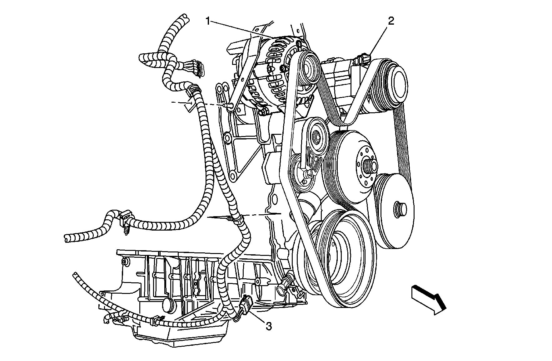
Figure 1:

Front of the Engine (4.3L)


Object Number: 886060  Size: MF
(1)Generator
(2)A/C Compressor Clutch Connector (C60)
(3)Crankshaft Position (CKP) Sensor Connector
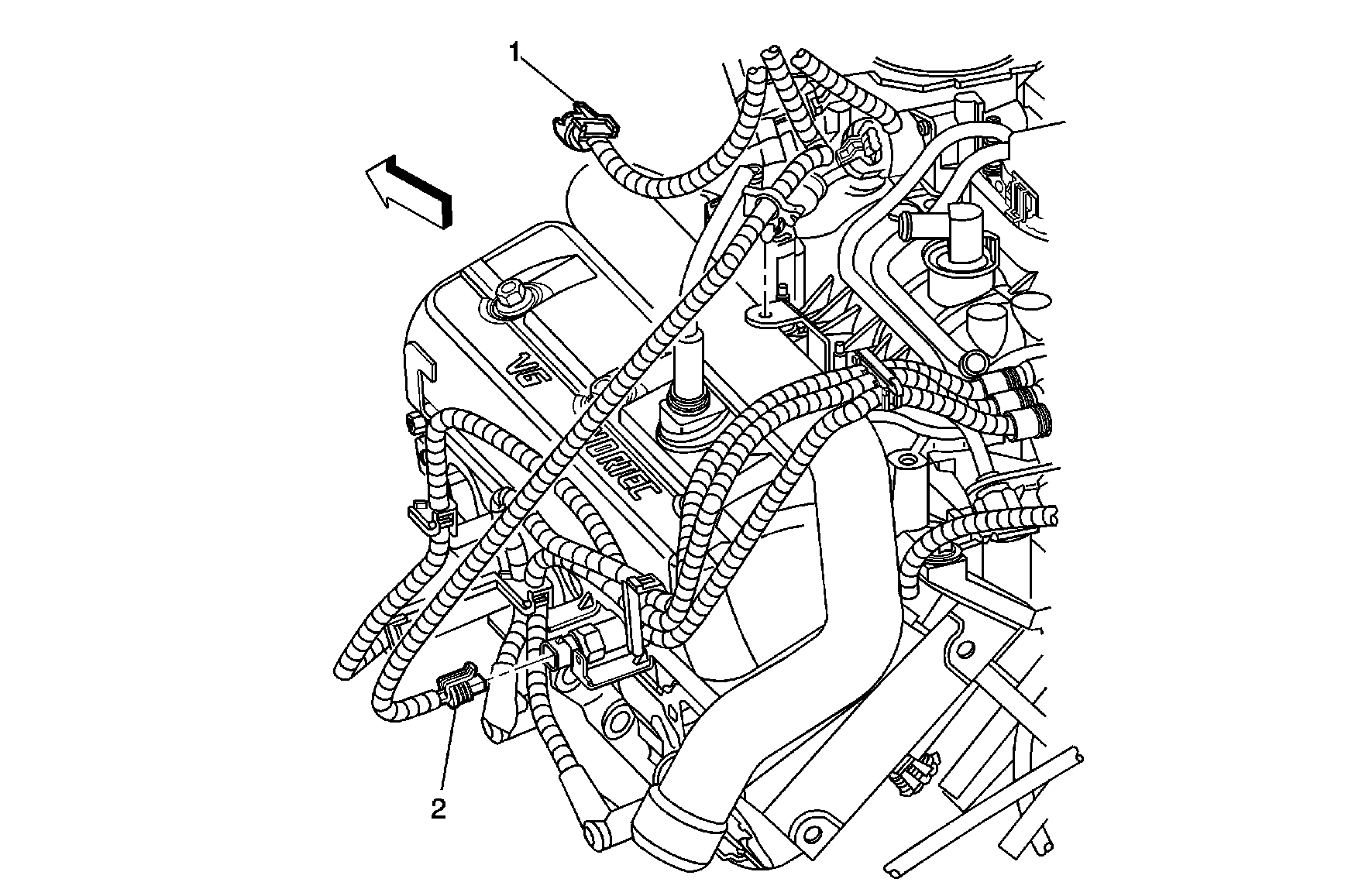
Figure 2:

Left Rear of the Engine (4.3L)


Object Number: 886062  Size: MF
(1)A/C High Pressure Switch Connector (C60)
(2)Engine Coolant Temperature (ECT) Sensor Connector
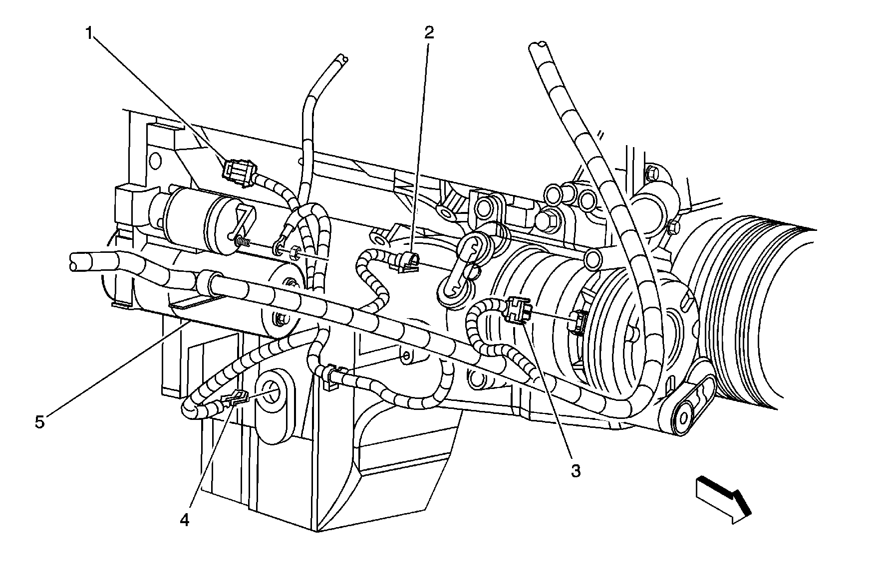
Figure 3:

Right Side of the Engine (4.8L/5.3L/6.0L)

Object Number: 886066  Size: MF
(1)Crankshaft Position (CKP) Sensor Connector
(2)A/C High Pressure Switch Connector (C60)
(3)A/C Compressor Clutch Connector (C60)
(4)Engine Oil Level Switch Connector
(5)Starter Motor
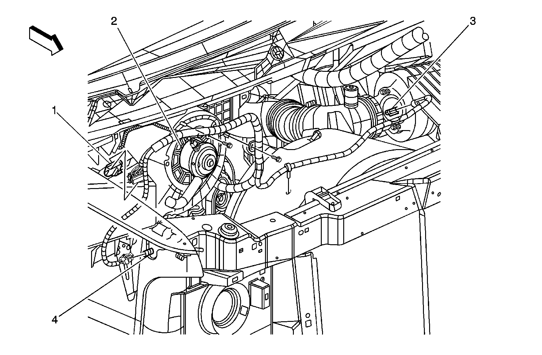
Figure 4:

Rear of the Engine Compartment


Object Number: 886081  Size: MF
(1)Blower Motor Resistor Assembly
(2)Blower Motor
(3)Intake Air Temperature (IAT) / Mass Air Flow (MAF) Sensor
(4)A/C Low Pressure Switch (C60)
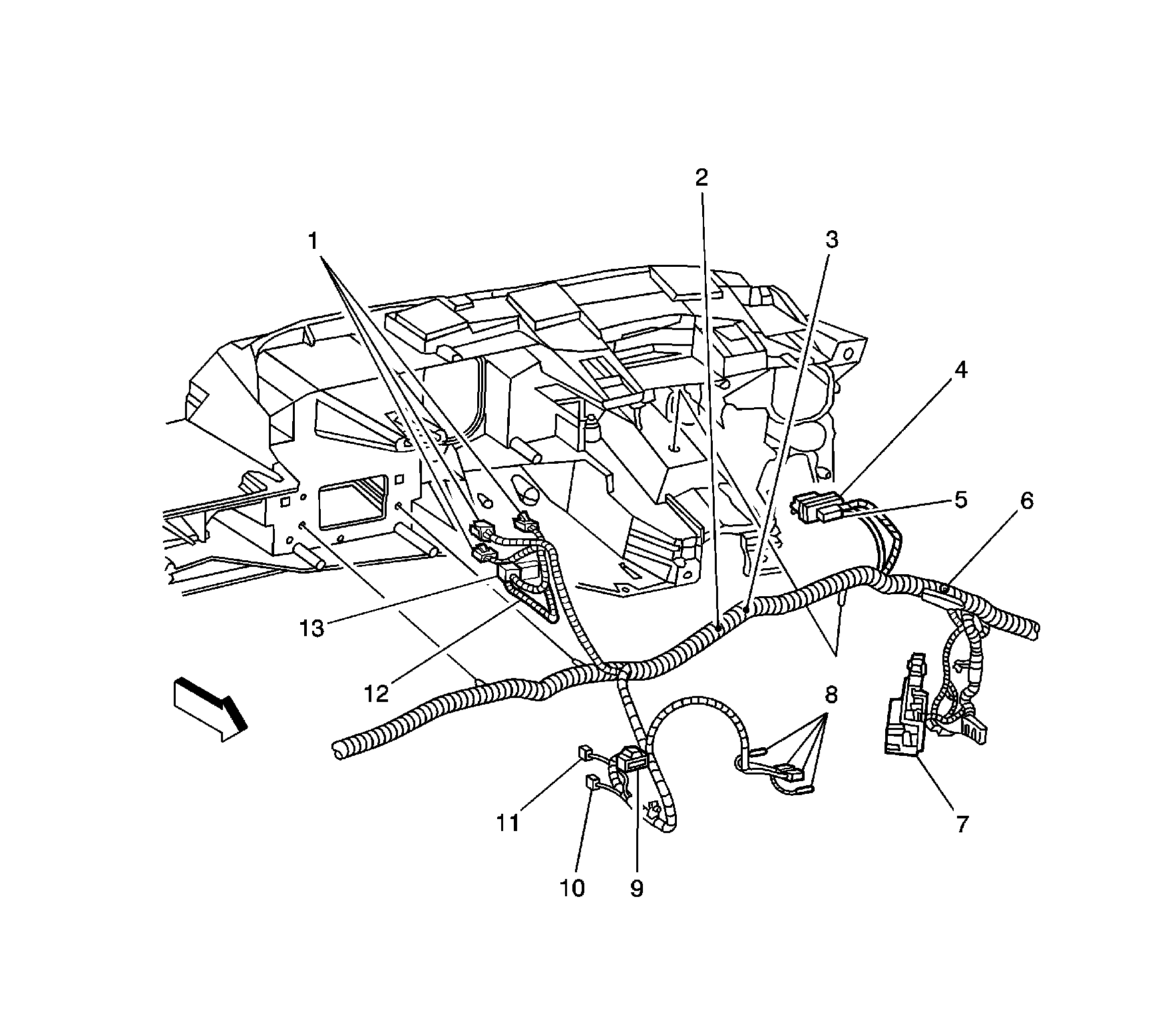
Figure 5:

I/P Harness Routing - Center of the I/P

Object Number: 883633  Size: LF
(1)HVAC Control Assembly Connectors
(2)S246 (DE7)
(3)S245 (DE7)
(4)Instrument Panel Cluster (IPC) Connector
(5)Remote Control Door Lock Receiver (RCDLR) Connector (AU0)
(6)S248
(7)C200
(8)Vehicle Communication Interface Module (VCIM) - C1, C2, C5, C6 (UE1)
(9)Turn Signal/Hazard Flasher Module Connector
(10)Cigar Lighter Connector
(11)Tow/Haul Switch Connector
(12)Antenna Connector
(13)Radio - C1, C2
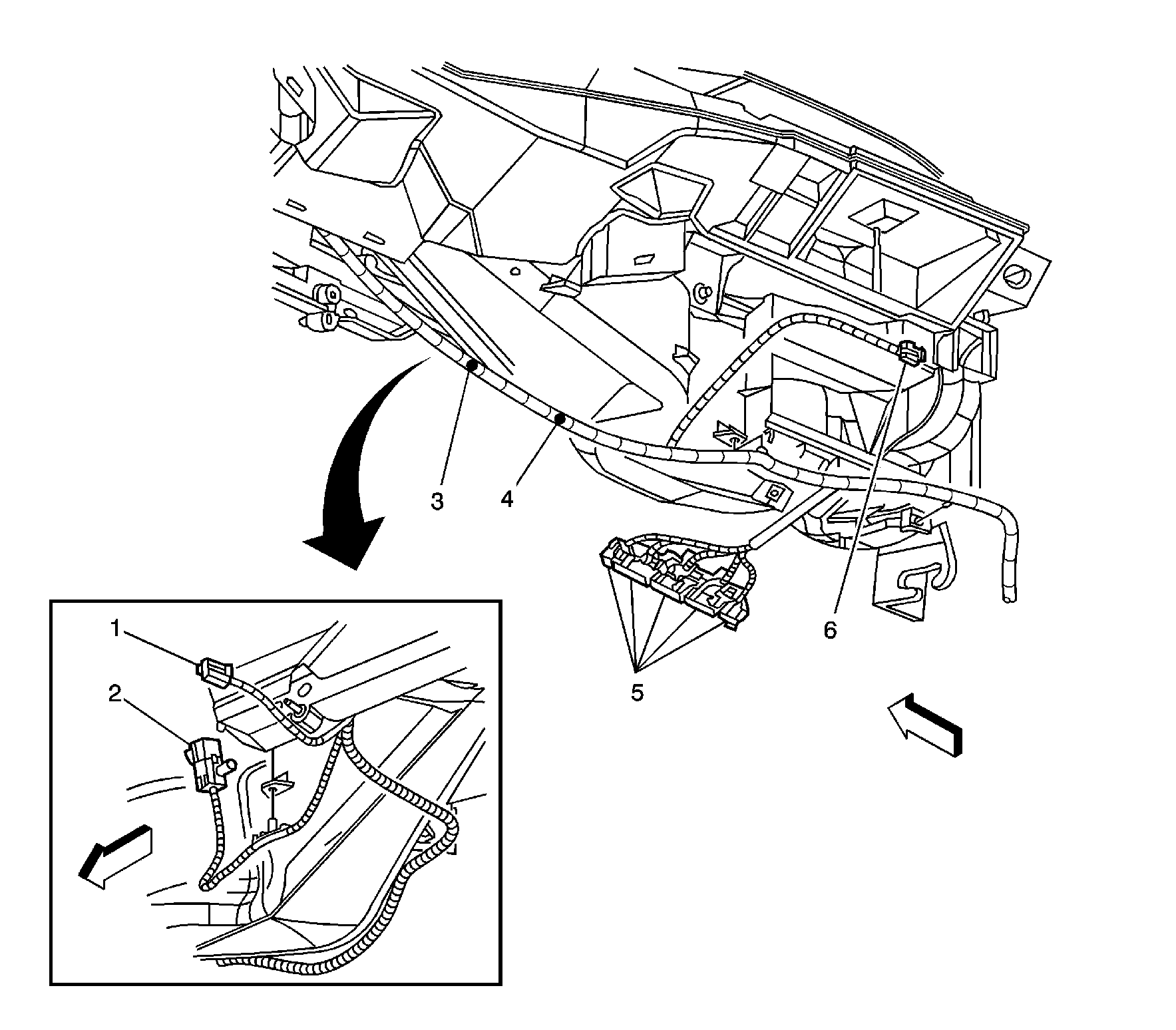
Figure 6:

I/P Harness Routing - Right Side of the I/P

Object Number: 883634  Size: LF
(1)Auxiliary Power Outlet Connector
(2)Inflatable Restraint I/P Module Connector
(3)S249
(4)S250
(5)Body Control Module (BCM) - C1, C2, C3, C4, C5
(6)Air Temperature Actuator Connector
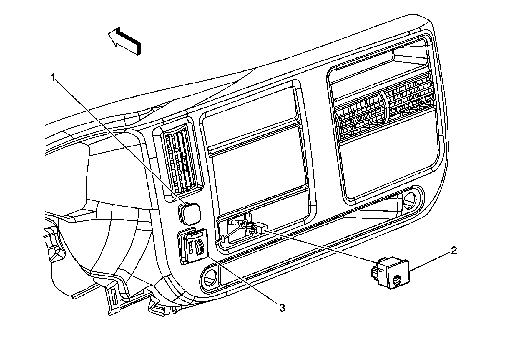
Figure 7:

Center of the I/P


Object Number: 886089  Size: MF
(1)Tow/Haul Switch
(2)Inflatable Restraint I/P Module Disable Switch (Heavy Duty)
(3)Blower Motor Switch - Auxiliary (C36)
Figure 8:

HVAC Controls Harness Routing


Object Number: 883639  Size: LF
(1)HVAC Control Assembly Connector - Rear Auxiliary (C69)
(2)HVAC Control Processor Connector - Auxiliary (C69)
(3)HVAC Control Assembly Connector - Front Auxiliary (C69)
(4)S355 (Rear Auxiliary Controls w/YF7)
(5)S307 (Rear Auxiliary Controls w/YF7)
(6)S354 (Rear Auxiliary Controls w/YF7)
(7)S305 (Rear Auxiliary Controls w/YF7)
(8)S306 (Rear Auxiliary Controls w/YF7)
(9)S314
(10)C303 (Rear Auxiliary Controls w/YF7/C69)
(11)Left B-Pillar
(12)C203 (YF7/DH6)
Figure 9:

Auxiliary Heater and A/C Harness Routing - Front (C36/C69)
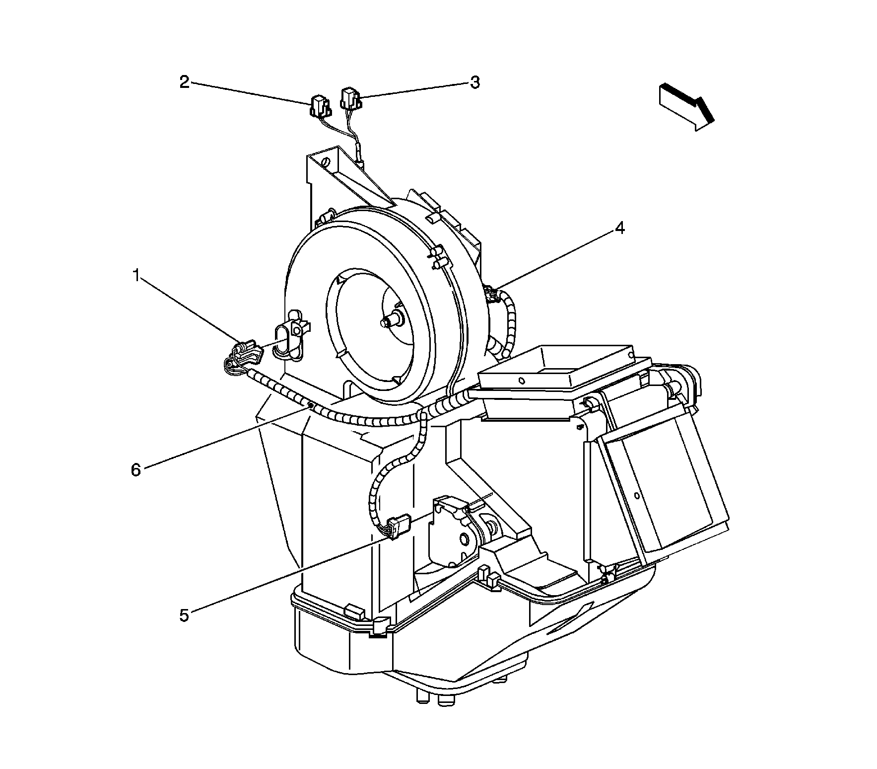

Object Number: 885010  Size: LF
(1)Blower Motor Resistor Assembly Connector - Auxiliary
(2)C409
(3)C407
(4)Blower Motor Connector - Auxiliary
(5)Air Temperature Actuator Connector - Auxiliary (C69)
(6)S413
Figure 10:

Auxiliary Heater and A/C Harness Routing - Rear (C36/C69)
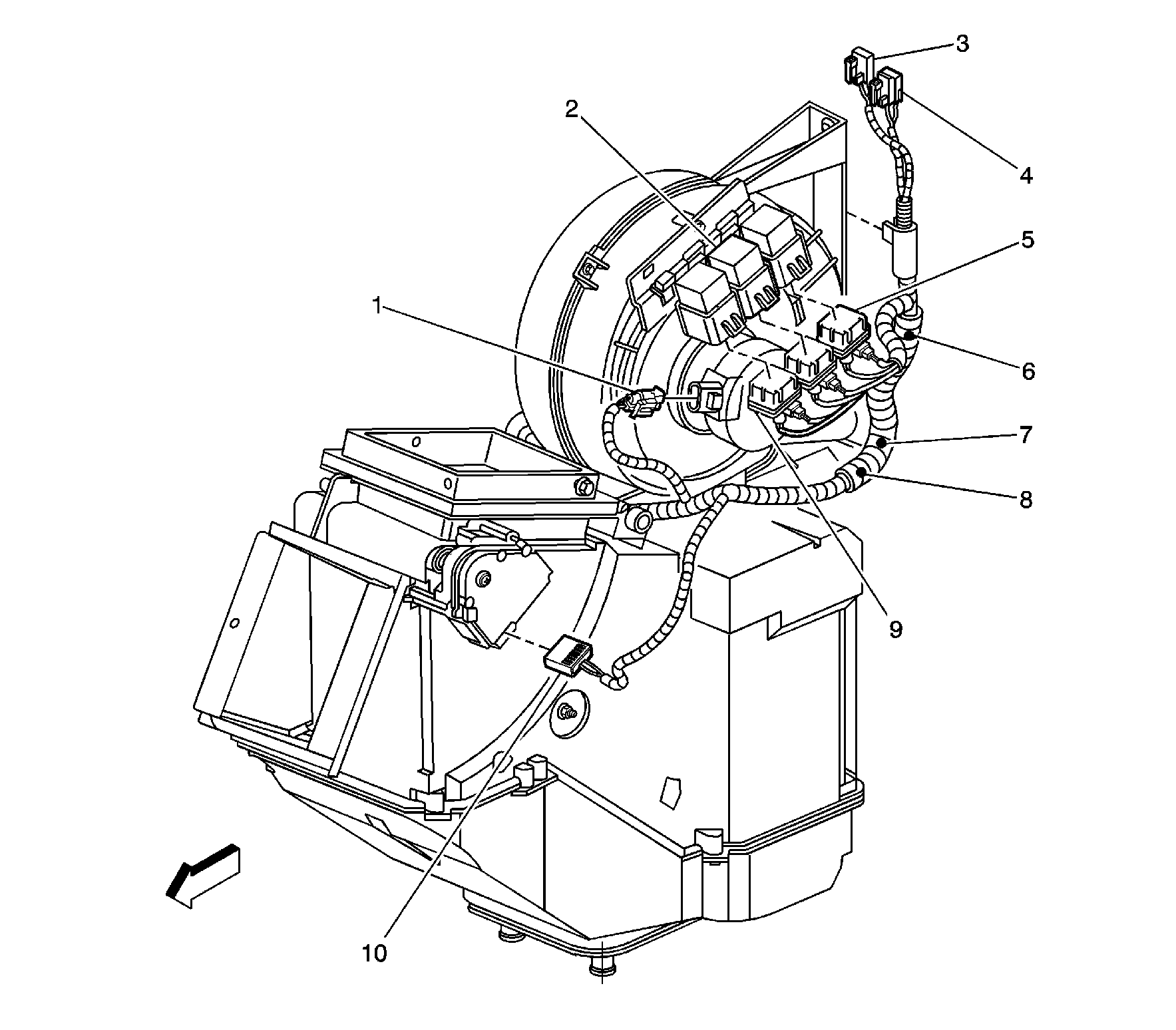

Object Number: 885012  Size: LF
(1)Blower Motor Connector - Auxiliary
(2)Medium Speed Blower Motor Relay - Auxiliary
(3)C407
(4)C409
(5)Low Speed Blower Motor Relay Connector - Auxiliary
(6)S412
(7)S405
(8)S411 (C69)
(9)High Speed Blower Motor Relay Connector - Auxiliary
(10)Mode Actuator Connector - Auxiliary (C69)