For 1990-2009 cars only
Tools Required
J 43181 Quick Connect Connector Removal Tool
Removal Procedure
- Remove the generator. Refer to Generator Replacement .
- Remove the intake manifold tube. Refer to Intake Manifold Tube Replacement .
- Remove the right exhaust pipe. Refer to Exhaust Pipe Replacement - Right Side .
- Remove the crankcase ventilation hose/pipe. Refer to Positive Crankcase Ventilation Hose/Pipe/Tube Replacement .
- Drain the cooling system. Refer to Cooling System Draining and Filling .
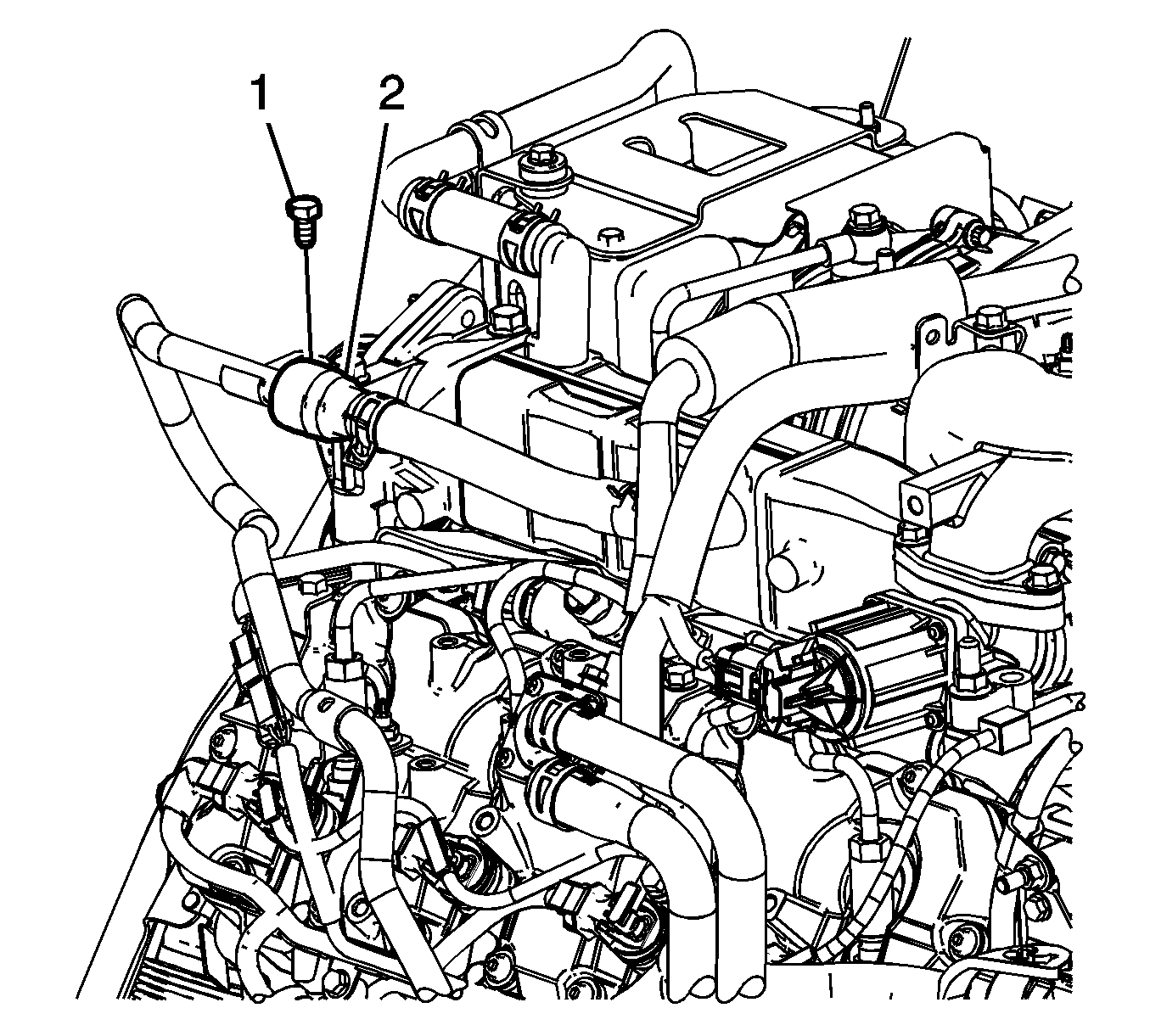
- Remove the heater inlet pipe bracket bolt (1).
- Using the J 43181 , disconnect the exhaust gas recirculation (EGR) cooler hose fitting (2) from the heater inlet pipe.
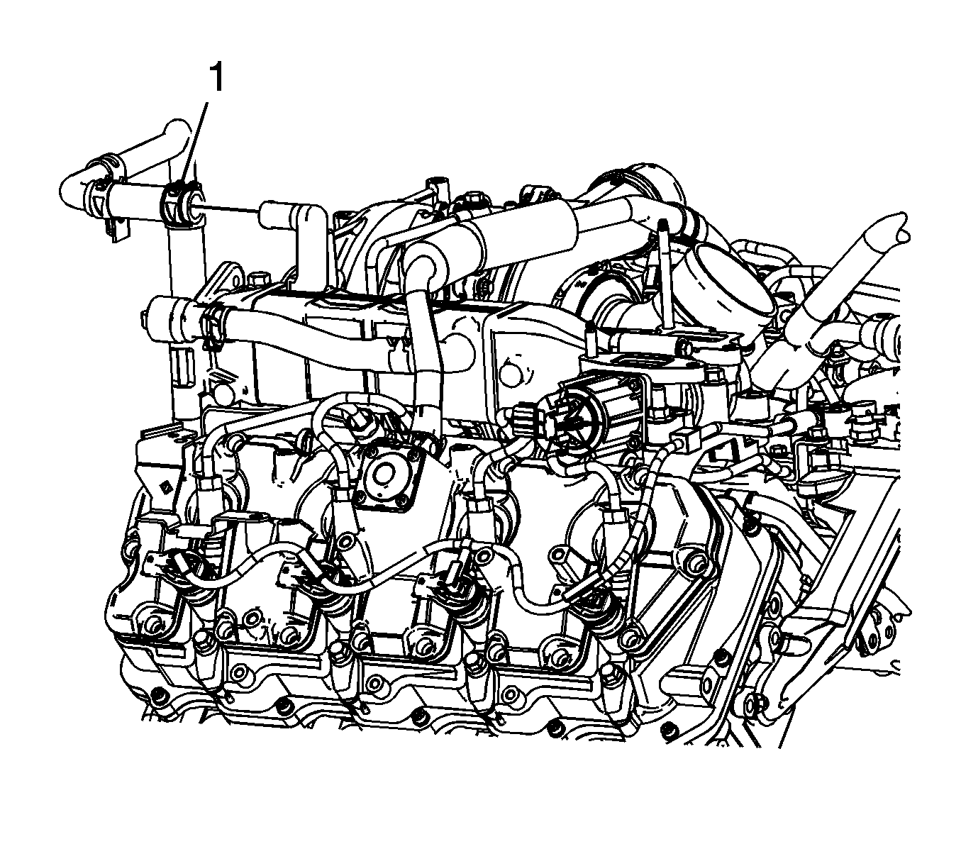
- Reposition the EGR cooler pipe clamp (1) and remove the EGR cooler pipe hose from the EGR cooler tube.
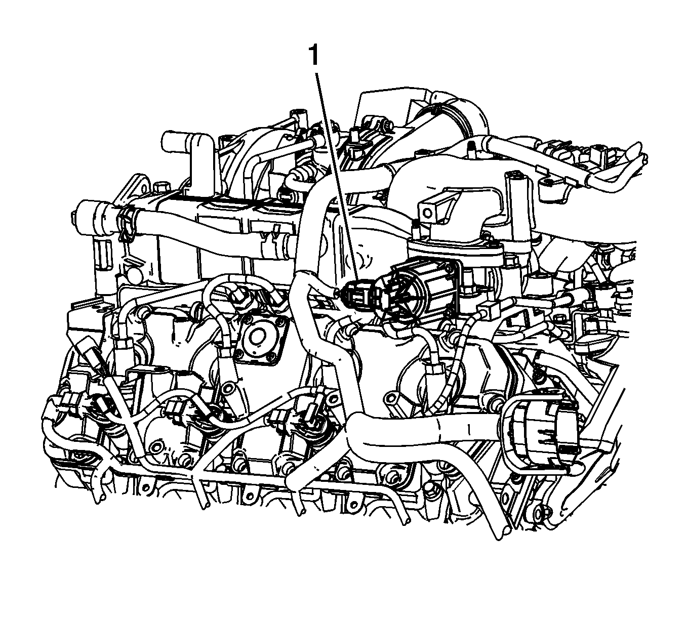
- Disconnect the engine wiring harness electrical connector (1) from the EGR valve.
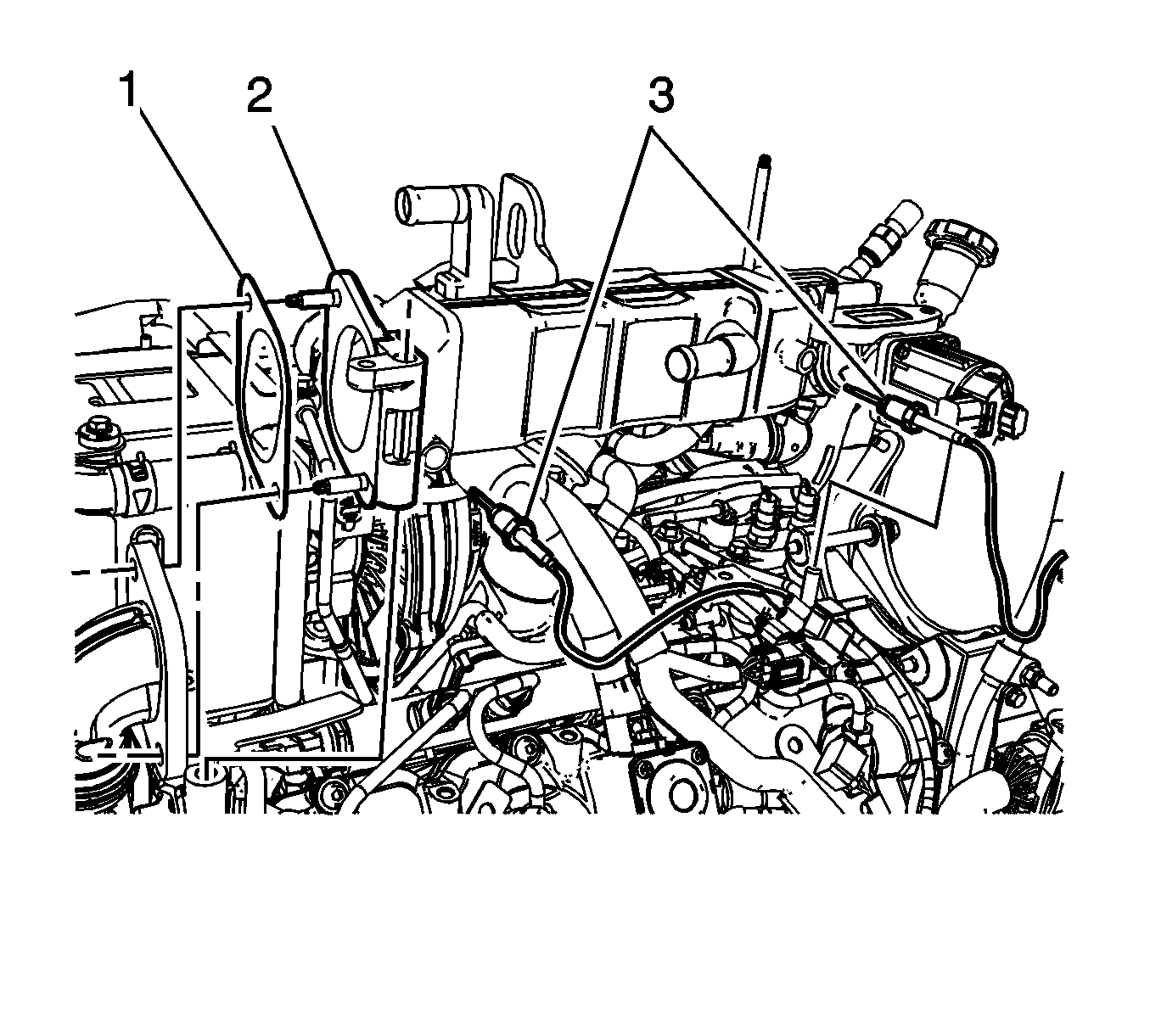
- Remove the EGR valve temperature sensors (3). Refer to Exhaust Gas Recirculation Valve Temperature Sensor Replacement - Position 1 and Exhaust Gas Recirculation Valve Temperature Sensor Replacement - Position 2.
- Remove the EGR valve/cooler tube assembly bolts and nut.
- Remove the EGR valve/cooler tube assembly (2) and gasket (1) from the engine and place on a clean work surface. Discard the gasket.
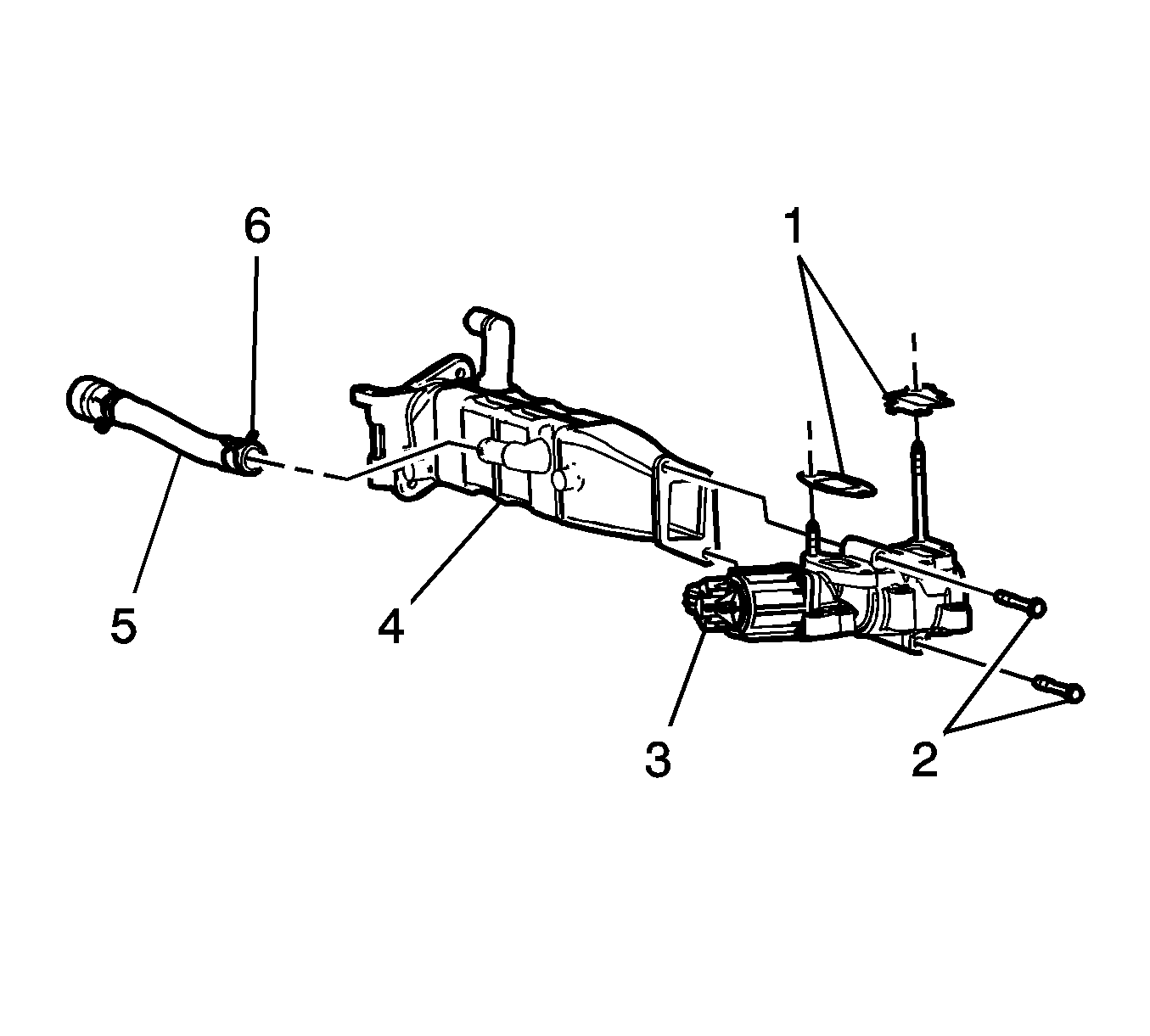
- On the bench, remove the EGR valve to EGR cooler tube bolts (2).
- Separate the EGR valve (3) from the EGR cooler tube (4).
- Remove and discard the intake manifold tube gaskets (1) as required.
- Reposition the EGR cooler hose clamp (6) and remove the EGR cooler hose (5) from the EGR cooler.
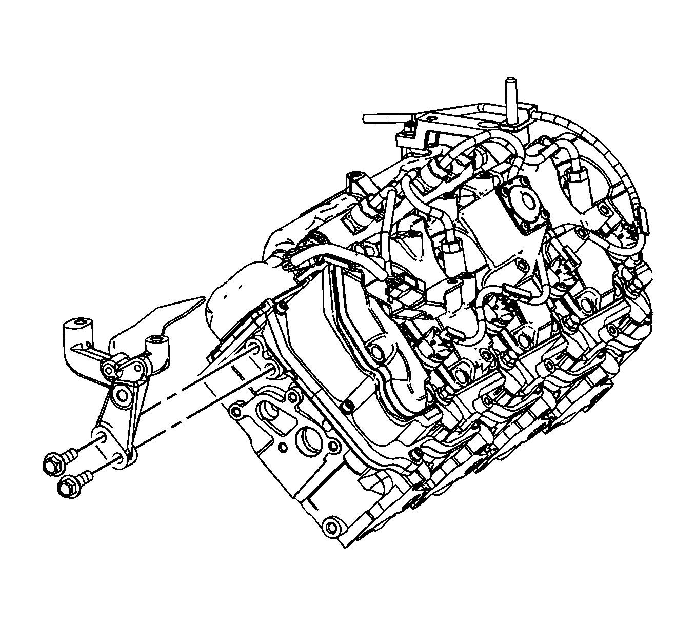
- If required, remove the EGR cooler tube bracket bolts and bracket.
Installation Procedure
- If required, position the EGR cooler tube bracket to the cylinder head and install the bolts.
- Install the EGR cooler hose (5) onto the EGR cooler tube and position the EGR cooler hose clamp (6).
- Install NEW intake manifold tube gaskets (1) as required.
- Position the EGR valve (3) to the EGR cooler tube (4).
- Install the EGR valve to EGR cooler tube bolts (2).
- Install a NEW gasket (1) to the EGR valve cooler tube assembly (2)
- Install the EGR valvecooler tube assembly (2)to the engine.
- Install the EGR valve/cooler tube assembly bolts and nut.
- Install the EGR Valve Temperature sensors. Refer to Exhaust Gas Recirculation Valve Temperature Sensor Replacement - Position 1 and Exhaust Gas Recirculation Valve Temperature Sensor Replacement - Position 2.
- Connect the engine wiring harness electrical connector (1) to the EGR valve.
- Install the EGR cooler pipe hose to the EGR cooler tube and reposition the EGR cooler pipe clamp (1).
- Connect the EGR cooler hose fitting (2) to the heater inlet pipe.
- Install the heater inlet pipe bracket bolt (1).
- Fill the cooling system. Refer to Cooling System Draining and Filling .
- Install the crankcase ventilation hose/pipe. Refer to Positive Crankcase Ventilation Hose/Pipe/Tube Replacement .
- Install the right exhaust pipe. Refer to Exhaust Pipe Replacement - Right Side .
- Install the intake manifold tube. Refer to Intake Manifold Tube Replacement .
- Install the generator. Refer to Generator Replacement .
Notice: Refer to Fastener Notice in the Preface section.

Tighten
Tighten the bolts to 25 N·m (18 lb ft).

Tighten
Tighten the bolts to 20 N·m (15 lb ft).

Tighten
Tighten the bolts to 25 N·m (18 lb ft).


Tighten
Tighten the bolt to 25 N·m (18 lb ft).
