Removal Procedure
- Remove the engine cover. Refer to
Engine Cover Replacement
.
- Remove the air cleaner assembly. Refer to
Air Cleaner Assembly Replacement
.
- Remove the fuel pipes/hoses. Refer to
Fuel Hose/Pipes Replacement - Engine Compartment
.
- Disconnect the air conditioning (A/C) compressor clutch, if equipped.
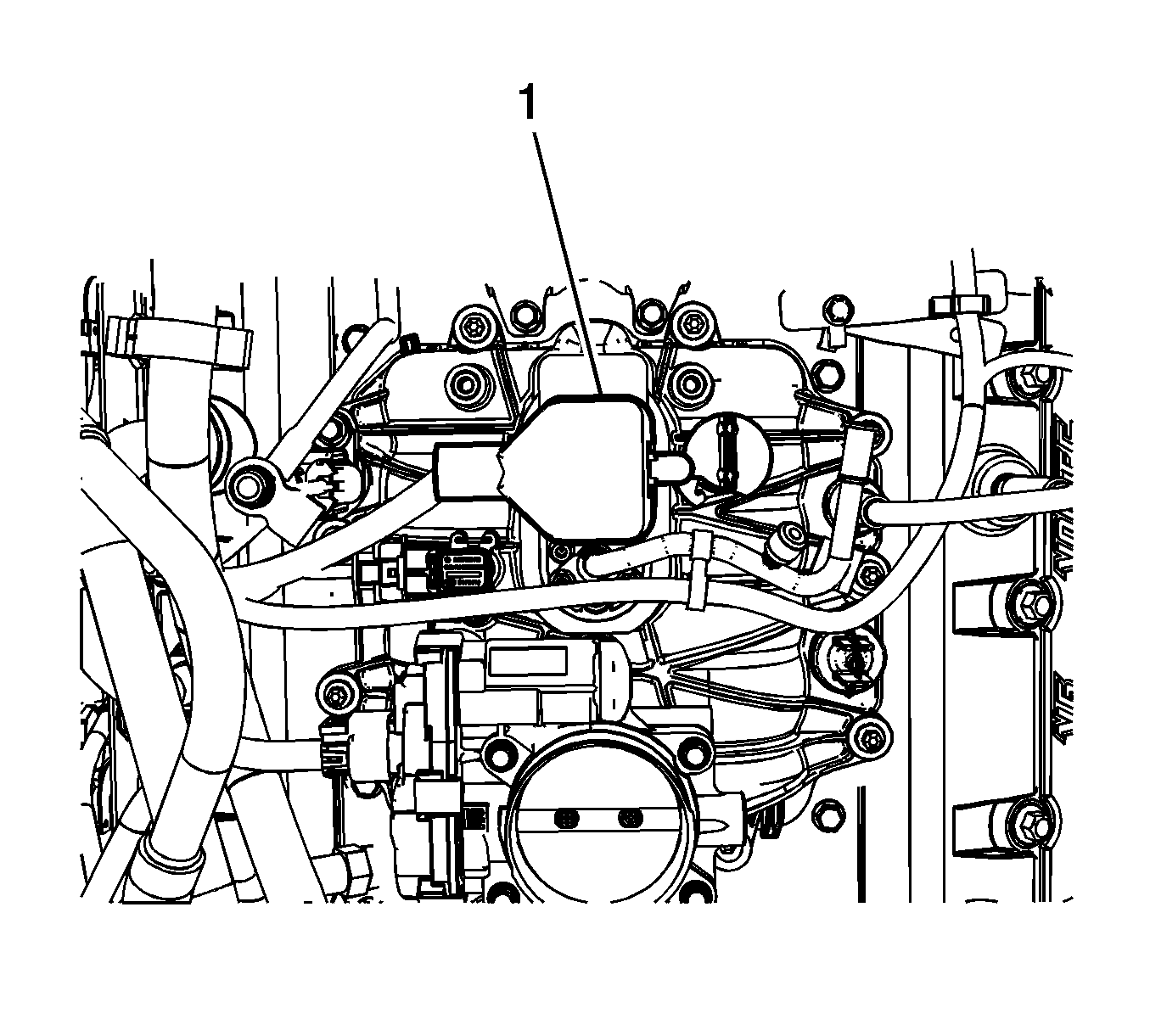
- Disconnect the control port injector module (1).
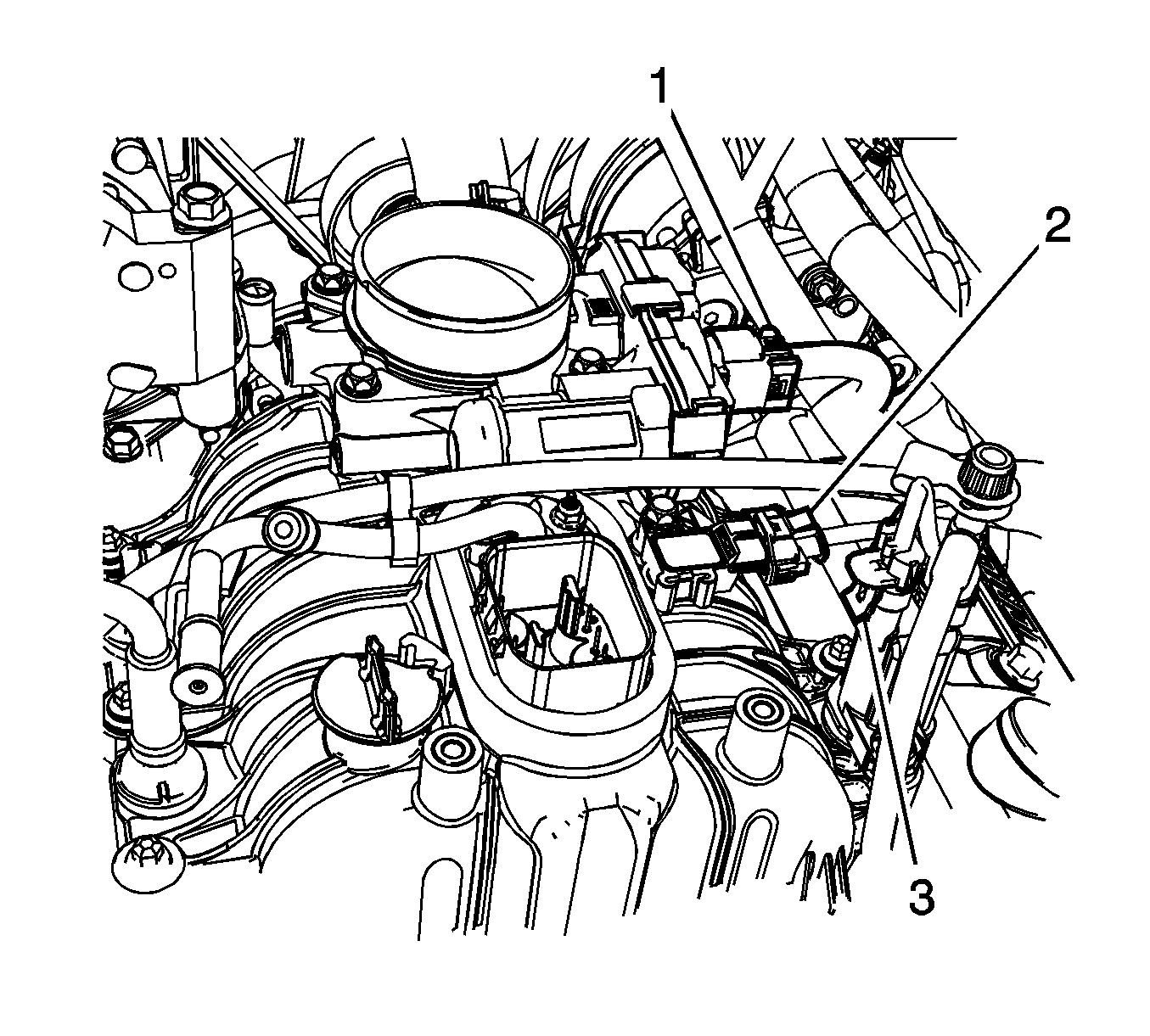
- Disconnect the following electrical connectors:
| • | The throttle body actuator (1) |
| • | The manifold absolute pressure (MAP) sensor (2) |
| • | The evaporative emission (EVAP) canister purge solenoid valve (3) |
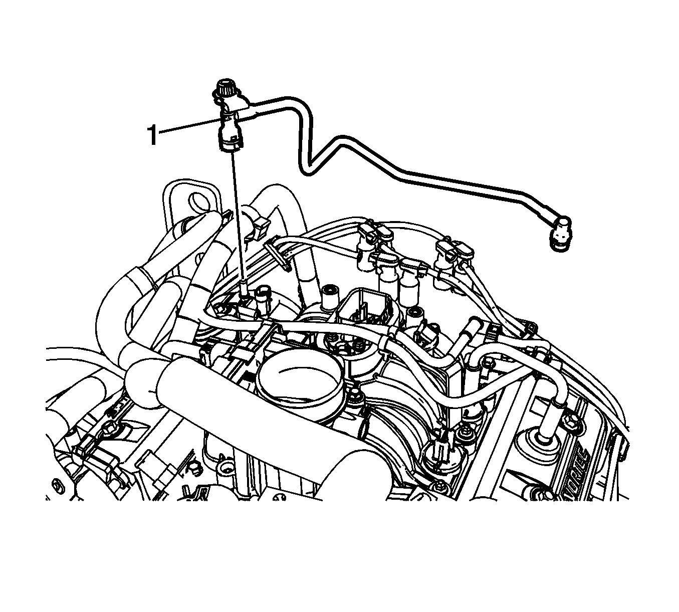
- Disconnect EVAP canister purge solenoid valve tube quick
connect fitting (1) from the EVAP purge solenoid valve. Refer to
Plastic Collar Quick Connect Fitting Service
.
- Reposition the tube out of the way.
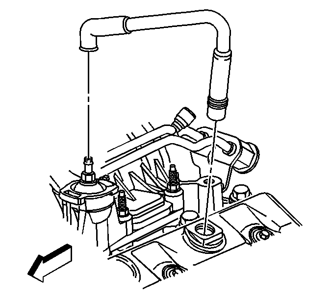
- Remove the positive crankcase ventilation (PCV) valve hose from the valve and rocker cover.
- Reposition the engine wiring harness aside.
- Disconnect the power brake booster vacuum hose from the vacuum fitting.
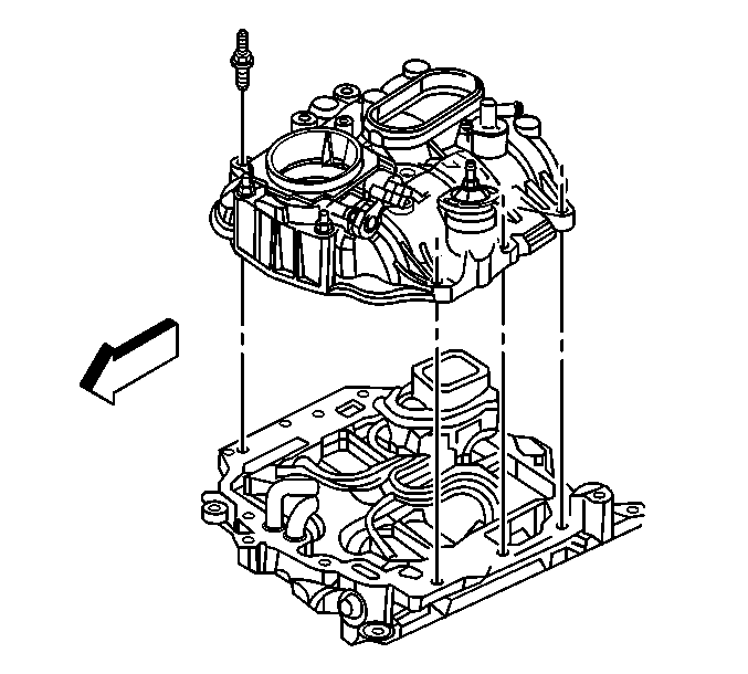
- Remove the intake manifold - upper studs.
- Remove the front 2 throttle body studs.
- Remove the intake manifold - upper.
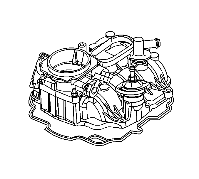
- Remove and discard the intake manifold - upper gasket.
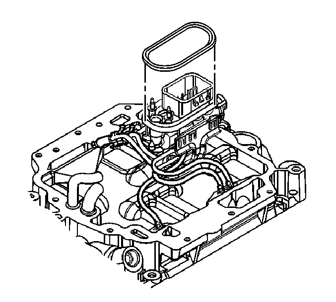
- Remove and discard the O-ring seal from the fuel meter body.
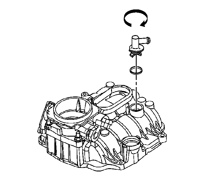
- If required, remove the power brake booster vacuum fitting.
- Remove and discard the O-ring seal.
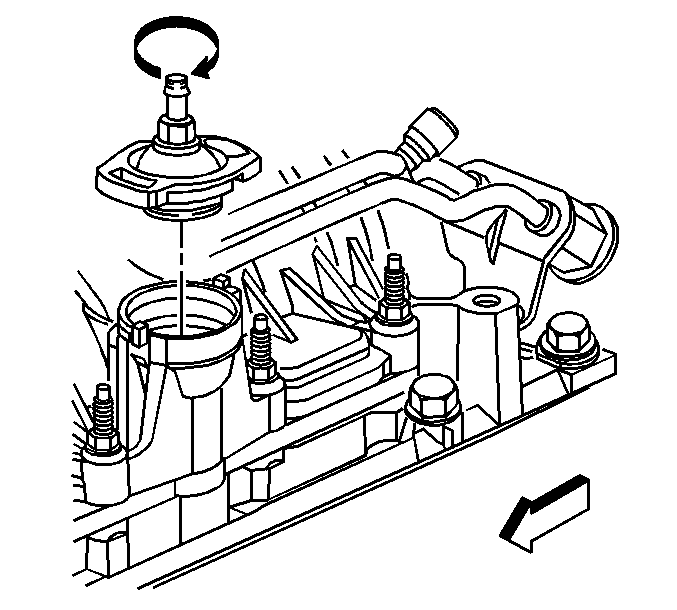
- If required, remove the PCV valve cover.
- Remove and discard the O-ring seal.
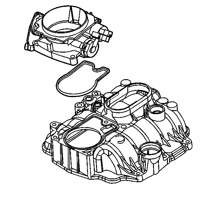
- If required, remove the rear throttle body stud.
- Remove the throttle body.
- Remove and discard the throttle body gasket.
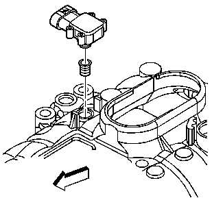
- If required, remove the MAP sensor.
- Remove and discard the MAP sensor seal.
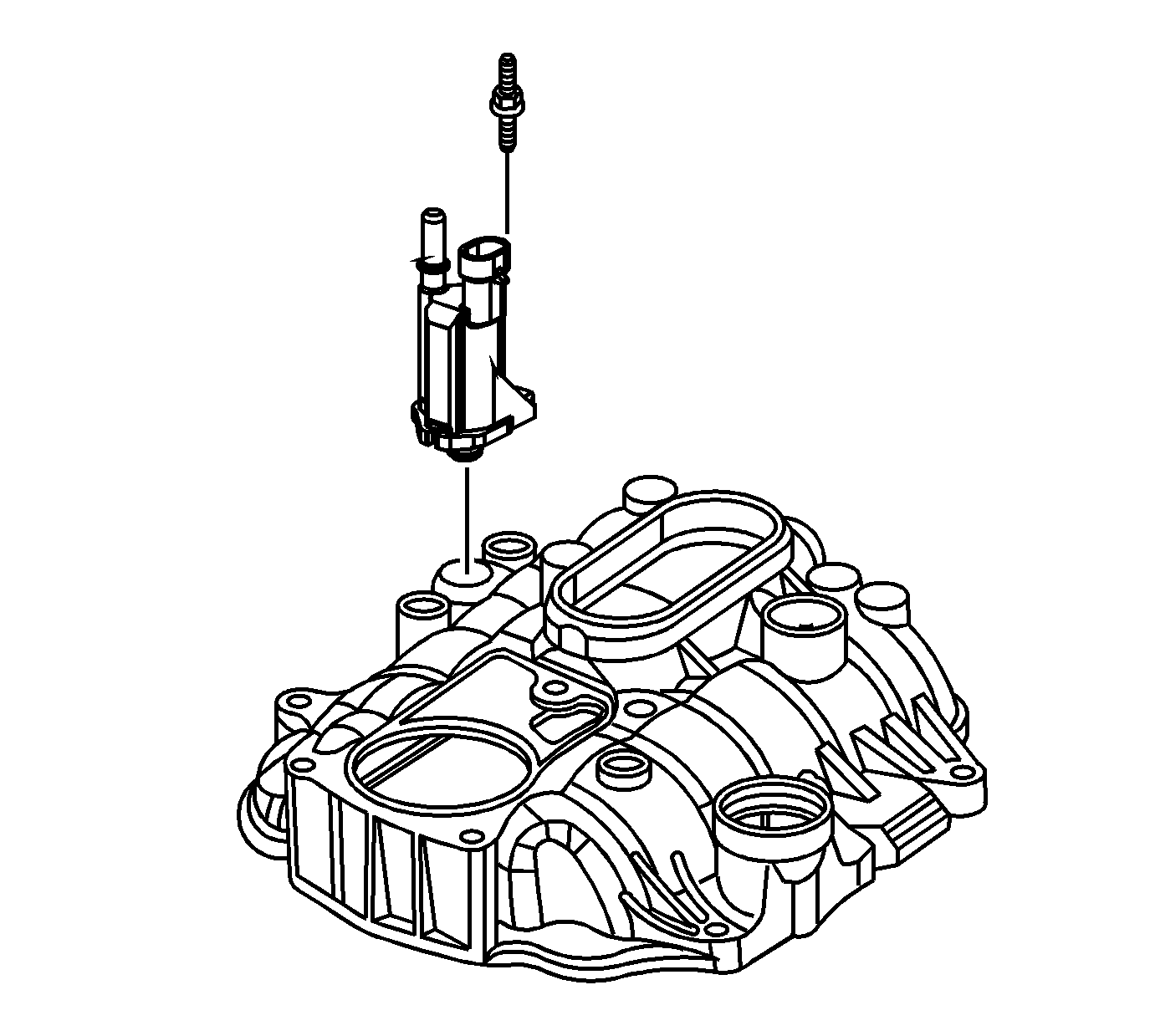
- If required, remove the EVAP canister purge solenoid valve studs.
- Remove the purge solenoid valve.
- Clean and inspect the intake manifold - upper, if necessary. Refer to
Intake Manifold Cleaning and Inspection
.
Installation Procedure
Notice: Refer to Fastener Notice in the Preface section.

- If required, install the purge solenoid valve.
- Install the EVAP canister purge solenoid valve studs. If reusing the old studs, apply threadlock to the threads. Refer to
Adhesives, Fluids, Lubricants, and Sealers
for the correct part number.
Tighten
Tighten the studs to 10 N·m (89 lb in).

- If required, install a NEW MAP sensor seal. Apply a small drop of clean engine oil to the seal.
- Install the MAP sensor.

- If required, install a NEW throttle body gasket.
- Install the throttle body.
- Install the rear throttle body stud. If reusing the old stud, apply threadlock to the threads. Refer to
Adhesives, Fluids, Lubricants, and Sealers
for the correct part number.
Tighten
Tighten the stud to 9 N·m (80 lb in).

- If required, install a NEW O-ring seal to the PCV cover. Apply clean engine oil to the seal.
- Install the PCV valve cover.

- If required, install a NEW O-ring seal. Apply clean engine oil to the seal.
- Install the power brake booster vacuum fitting.

- Install a NEW O-ring seal to the fuel meter body.

- Install a NEW upper intake manifold gasket.

- Install the intake manifold - upper.
- If reusing the old throttle body/intake manifold studs, apply threadlock to the threads. Refer to
Adhesives, Fluids, Lubricants, and Sealers
for the correct part number.
- Install the front two throttle body studs.
- Install the intake manifold - upper studs.
Tighten
Tighten the studs to 9 N·m (80 lb in).
- Connect the power brake booster vacuum hose to the vacuum fitting.

- Position the engine wiring harness.
- Install the PCV valve hose to the valve cover and rocker cover.

- Position the EVAP canister purge solenoid tube, and connect
the tube quick connect fitting (1) to the EVAP purge solenoid valve. Refer to
Plastic Collar Quick Connect Fitting Service
.

- Connect the following electrical connectors:
| • | The EVAP canister purge solenoid valve (3) |
| • | The throttle body actuator (1) |

- Connect the control port injector module (1).
- Connect the A/C compressor clutch, if equipped.
- Install the fuel pipes/hoses. Refer to
Fuel Hose/Pipes Replacement - Engine Compartment
.
- Install the air cleaner assembly. Refer to
Air Cleaner Assembly Replacement
.
- Install the engine cover. Refer to
Engine Cover Replacement
.


