Customer Satisfaction - Missing Circuits for Trailer Lights - Trailer Lights Inoperative

| Subject: | 07335 -- Missing Circuits for Trailer Lights - Trailer Lights Inoperative |
| Models: | 2008 Chevrolet Express |
| 2008 GMC Savana |
| Equipped with Trailer Wiring Harness (RPO UY7) and Upfitter Recreation Vehicle Package (RPO YF7) |
*****THIS PROGRAM IS IN EFFECT UNTIL FEBRUARY 28, 2009.*****
Condition
Certain 2008 model year Chevrolet Express and GMC Savana vehicles equipped with a trailer wiring harness (RPO UY7) and an upfitter recreational vehicle package (RPO YF7) may have a condition in which a wiring harness may be missing circuits. Without these circuits, the trailer lights will not illuminate.
Correction
Dealers are to install the missing circuits.
Vehicles Involved
Involved are certain 2008 model year Chevrolet Express and GMC Savana vehicles equipped with a trailer wiring harness (RPO UY7) and upfitter recreation vehicle package (RPO YF7), and built within these VIN breakpoints:
Year | Division | Model | From | Through |
|---|---|---|---|---|
2008 | Chevrolet | Express | 81105472 | 81159373 |
2008 | GMC | Savana | 81108744 | 81152155 |
Important: Dealers are to confirm vehicle eligibility prior to beginning repairs by using the GM Vehicle Inquiry System (GMVIS). Not all vehicles within the above breakpoints may be involved.
For dealers with involved vehicles, a listing with involved vehicles containing the complete vehicle identification number, customer name, and address information has been prepared and will be provided through GM DealerWorld Recall Information. Dealers will not have a report available if they have no involved vehicles currently assigned.
The listing may contain customer names and addresses obtained from Motor Vehicle Registration Records. The use of such motor vehicle registration data for any purpose other than follow-up necessary to complete this program is a violation of law in several states/provinces/countries. Accordingly, you are urged to limit the use of this report to the follow-up necessary to complete this program.
Parts Information
Tie straps and conduit required to complete this program are to be obtained from General Motors Service and Parts Operations (GMSPO). Please refer to your "involved vehicles listing" before ordering parts. Normal orders should be placed on a DRO = Daily Replenishment Order. In an emergency situation, parts should be ordered on a CSO = Customer Special Order.
Important: Since there are only 119 vehicles involved in this program, dealers should not order parts for use as shelf stock. Parts should only be ordered after dealers determine they have involved vehicles and do not have the necessary parts on hand.
Part Number | Description | Qty/ Vehicle |
|---|---|---|
12051375 | Conduit, Wrg Harn 6 mm (*17,18,24,27)(1/4 I.D. X 15 FT) | 213 cm (7 ft) |
12337820 | Strap, Adj Tie, 7 mm Wide, 255 mm Lg | 10 |
The following parts can be found in the GM Approved J 38125 Terminal Repair Kit. Additional or replacement terminals may be purchased from SPX/Kent-Moore at 1-800-GM-TOOLS (1-800-468-6657).
Part Number | Description | Quantity/Vehicle |
|---|---|---|
SNAC3-A021T-M0.64 (BCM) (Circuits 5186 & 5187) | Terminals (Delphi Tray 20) | 2 |
8100-4443 (UBEC) (Circuits 5186 & 5187) | Terminals (Sumitomo Tray 22) | 2 |
8100-4444 (UBEC & BBEC) (Circuits 1624 & 2109) | Terminals (Sumitomo Tray 22) | 4 |
8100-4445 (UBEC) (Circuits 47 & 3940) | Terminals (Sumitomo Tray 22) | 2 |
12089496 (Ground Circuit 350) | Ground Ring Terminal (Delphi Tray 5) | 1 |
1839906 (Splice) (Circuit 6311) | Metal Splice Clip (Delphi Tray 1) | 1 |
The following parts are to be obtained locally:
Size | Description | Quantity/Vehicle |
|---|---|---|
22 (0.35 m) Gauge Wire (Yellow) (Circuit 5187) | Automotive Electrical Wire | 305 cm (10 ft) |
22 (0.35 m ) Gauge Wire (Orange) (Circuit 5186) | Automotive Electrical Wire | 305 cm (10 ft) |
16 (1.0 m) Gauge Wire (LT Green) (Circuit 1624) | Automotive Electrical Wire | 201 cm (6 ½ ft) |
16 (1.0 m) Gauge Wire (Brown) (Circuit 2109) | Automotive Electrical Wire | 201 cm (6 ½ ft) |
12 (3.0 m) Gauge Wire (Dark Blue) (Circuit 47) | Automotive Electrical Wire | 122 cm (4 ft) |
12 (3.0 m) Gauge Wire (Red/White) (Circuit 3940) | Automotive Electrical Wire | 122 cm (4 ft) |
20 (0.5 m) Gauge Wire (Black) (Circuit 350) | Automotive Electrical Wire | 91 cm (3 ft) |
20 (0.5 m) Gauge Wire (Light Blue/White) (Circuit 6311) | Automotive Electrical Wire | 152 cm (5 ft) |
Service Procedure
- Record all the preset radio stations from the radio/
- Open the hood and disconnect the negative battery cable. Refer to Battery Negative Cable Disconnection and Connection in SI.
- Disable the SIR system. Refer to SIR Disabling and Enabling in SI.
- Remove the right side knee bolster panel. Refer to Passenger Knee Bolster Replacement in SI.
- Remove the left side knee bolster panel. Refer to Driver Knee Bolster Replacement in SI.
- Remove the left side knee bolster bracket. Refer to Driver Knee Bolster Bracket Replacement in SI..
- Remove the IP lower center extension panel and compartment door. Refer to Instrument Panel Lower Extension Replacement in SI.
- Remove the IP cluster trim plate bezel. Refer to Instrument Panel Cluster Trim Plate Bezel Replacement in SI.
- Remove the radio. Refer to Radio Replacement in SI.
- Remove the body control module (BCM) bracket. Refer to Body Control Module Replacement in SI.
- Disconnect the BCM connector X4 (black in color, 25 cavities) (1) and release the blue locking tab in the connector using a small pick.
- Add circuits (5186 - orange wire and 5187 - yellow wire) left and right trailer turn signal lamps to the BCM. Refer to Trailer Connector/Provision Schematics in SI.
- Follow the existing IP wiring harness when routing the conduit
- Remove the left hinge pillar trim. Refer to Body Hinge Pillar Trim Panel Replacement in SI.
- Remove the left front sill plate. Refer to Front Side Door Step Mat Replacement in SI.
- Remove the left front seat assembly. Refer to Driver and Passenger Seat Replacement in SI.
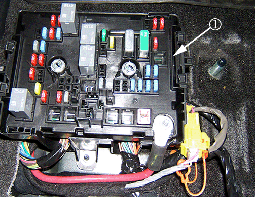
- Remove the fuse block cover on the fuse block body bus electrical center (BBEC).
- Remove the BBEC. Refer to Body Wiring Harness Junction Block Replacement in SI.
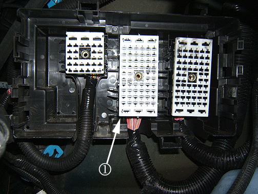
- Locate connector X1 (1) (black in color, 62 cavities) at the BBEC.
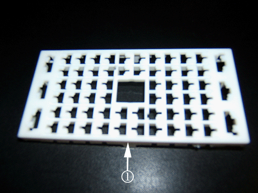
- Remove the bottom plastic protector cover (1) from the BBEC connector X1 (black in color, 62 cavities) (1).
- Remove the top terminal position assurance lock tab retainer (1) from the BBEC connector X1.
- Add circuit 1624 (trailer backup lamp supply voltage) (light green wire) to the BBEC.
- Add circuit 2109 (trailer park lamp supply voltage) (brown wire) to BBEC.
- Install the top terminal position assurance lock tab retainer to the BBEC connector X1.
- Install the bottom plastic protector cover to the BBEC connector X1 (black in color, 62 cavities).
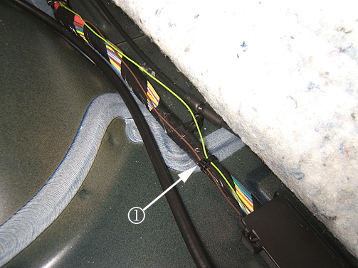
- Route the light green wire and brown wire inside the plastic floor harness retainer following the existing floor harness while securing with a tie strap (1).
- Follow the floor harness until you get to the left front main harness pass-thru grommet. The light green wire and brown wire will be pushed through the grommet and installed into the UBEC later.
- Add circuit 47 (trailer brake signal) (dark blue wire).
- Add circuit 3940 (battery feed) (red/white wire).
- Add new circuit 6311 (CHMSL/stop lamp supply voltage signal) (light blue/white wire)..
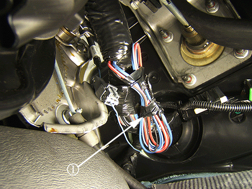
- Bundle one end of the following seven wires together.
- Tape (1) the bundled wires around a screwdriver shaft, leaving the tip showing.
- Push the screwdriver (1) through the grommet out toward the engine compartment.
- Remove the water deflector (1) from the left fender and the left brace (2).
- Gasoline engine only: Remove the air cleaner assembly from the vehicle. Refer to Air Cleaner Assembly Replacement in SI.
- * Diesel engine only: Remove the two master cylinder nuts and reposition the master cylinder assembly up away from the UBEC
- Remove the under hood bus electrical center (UBEC). Refer to Accessory Wiring Junction Block Replacement in SI.
- Remove the horn. Refer to Horn Replacement in SI.
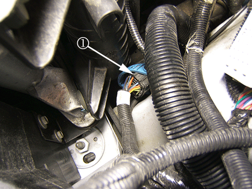
- Locate connector X100 (black in color, 40 cavities) (1) at the left front inner fender.
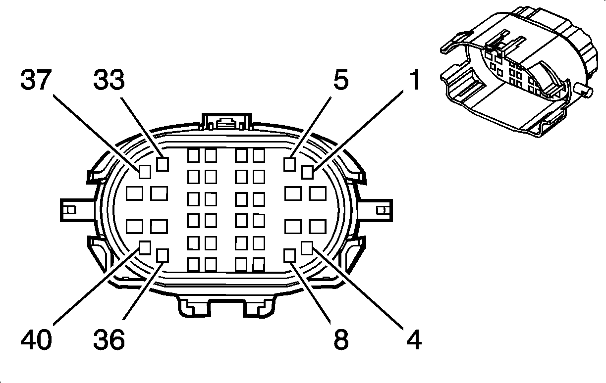
- Disconnect connector X100 and locate the light blue/white wire in cavity 1 of the connector as shown in the graphic above.
- Install the horn. Refer to Horn Replacement in SI.
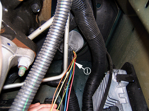
- Route the remaining six wires (1) that were previously pushed through the grommet along the side of the existing under hood harness to the UBEC connector X3.
- Locate the UBEC connector X3 (1) (gray in color, 62 cavities).
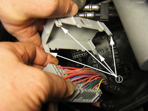
- Remove the bottom plastic protector cover from connector X3 by releasing the four retaining tabs (1).
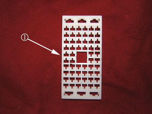
- Remove the top terminal position assurance lock tab retainer (1) from connector X3.
- Add terminal 8100-4443 from the Sumitomo tray 22 to the end of the orange wire (circuit 5186). Refer to Repairing Connector Terminals in SI.
- Add terminal 8100-4443 from the Sumitomo tray 22 to the end of the yellow wire (circuit 5187). Refer to Repairing Connector Terminals in SI.
- Add terminal 8100-4445 from Sumitomo tray 22 to the end of the dark blue wire (circuit 47). Refer to Repairing Connector Terminals in SI.
- Add terminal 8100-4445 from Sumitomo tray 22 to the end of the red/white wire (circuit 3940). Refer to Repairing Connector Terminals in SI.
- Add terminal 8100-4444 from the Sumitomo tray 22 to the end of the light green wire (circuit 1624). Refer to Repairing Connector Terminals in SI.
- Add terminal 8100-4444 from the Sumitomo tray 22 to the end of the brown wire (circuit 2109). Refer to Repairing Connector Terminals in SI.
- Install the top terminal assurance lock onto the UBEC connector X3.
- Install the bottom plastic protector cover for the UBEC connector X3.
- Tape the seven new wires to the existing wiring harness.
- Seal and tape the new circuit wires at the grommet.
- Install the UBEC. Refer to Accessory Wiring Junction Block Replacement in SI.
- Gasoline engine only: Install the air cleaner assembly. Refer to Air Cleaner Assembly in SI.
- Diesel engine only: Install the master cylinder and nuts.
- Install the left fender to the radiator support brace and bolts.
- Install the water deflector.
- Add the new ground circuit 350 (ground) (black wire) from inside the vehicle.
- The four trailer brake control wires should all have blunt cuts on the end. Each wire should be taped individually and then taped together as a group.
- Bundle the four wires up together and secure with tape (1) to the left side of the main harness/
- Reposition the left front floor carpet or rubber mat back down into position.
- Install the radio. Refer to Radio Replacement in SI.
- Install the IP cluster trim plate bezel. Refer to Instrument Panel Cluster Trim Plate Bezel Replacement in SI.
- Install the left side knee bolster bracket. Refer to Driver Knee Bolster Bracket Replacement in SI.
- Install the IP lower center extension panel and compartment door. Refer to Instrument Panel Lower Extension Replacement in SI.
- Install the left side knee bolster panel. Refer to Driver Knee Bolster Replacement in SI.
- Install the BCM to the bracket and IP carrier. Refer to Body Control Module Replacement in SI.
- Install the right side knee bolster panel. Refer to Passenger Knee Bolster Replacement in SI.
- Reposition the left front floor carpet back down into position.
- Install the BBEC and top fuse block cover. Refer to Body Wiring Harness Junction Block Replacement in SI.
- Install the left front seat assembly. Refer to Driver and Passenger Seat Replacement in SI.
- Install the left front sill plate. Refer to Front Side Door Step Mat Replacement in SI.
- Install the left front hinge panel. Refer to Body Hinge Pillar Trim Panel Replacement in SI.
- Install the left front floor mat.
- Enable the SIR system. Refer to SIR Disabling and Enabling in SI.
- Connect negative battery cable. Refer to Battery Negative Cable Disconnection and Connection in SI.
- Close the hood.
- Verify the proper operation of all trailer running lights, turn signals, and brake lights.
- Reset the radio clock and radio stations.
Caution: The ignition and start switch must be in the OFF or LOCK position, and all electrical loads must be OFF before servicing any electrical component. Disconnect the negative battery cable to prevent an electrical spark should a tool or equipment come in contact with an exposed electrical terminal. Failure to follow these precautions may result in personal injury and/or damage to the vehicle or its components.
If the vehicle is equipped with an auxiliary battery, the auxiliary negative battery cable will also need to be disconnected.
Caution: When performing service on or near the SIR components or the SIR wiring, the SIR system must be disabled. Failure to observe the correct procedure may cause deployment of the SIR components and serious injury can occur. Failure to observe the correct procedure could also result in unnecessary SIR system repairs.
Tip
It is necessary to lower the complete steering column before the IP cluster trim plate bezel is removed.
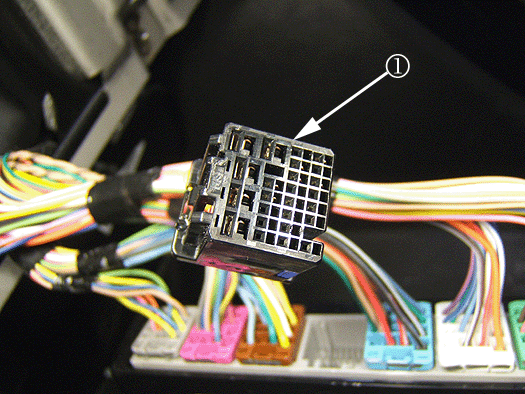
Caution: Do NOT try to completely remove the blue terminal locking tab from the BCM connector X4 (1) or damage to the connector will result. The blue locking tab will slightly pop up when in the release position.
Caution: The proper gauge wire for each circuit must be used to maintain the designed circuit protection and terminal acceptance. The specified wire color should also be used for future serviceability.
| 12.1. | Obtain two 22 (0.35 m) gauge wires, one yellow wire, and one orange wire and cut the wires to 305 cm (10 ft) lengths. |
| 12.2. | Add terminal SNAC3-A02IT-M0.64 from Delphi tray 20 to one end of the orange wire (circuit 5186). Refer to Repairing Connector Terminals in SI. |
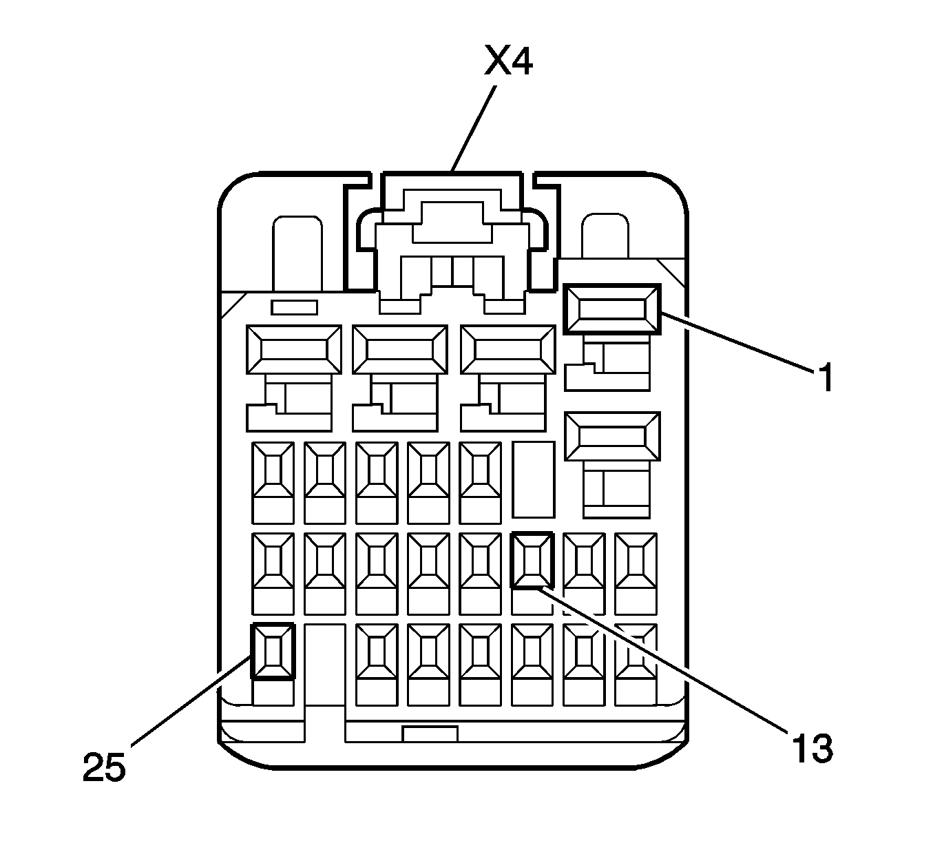
| 12.3. | Locate cavity 13 in the BCM connector X4 (black in color, 25 cavities) as shown in the graphic above. |
| 12.4. | Install the orange wire (circuit 5186) with terminal SNAC3-A02IT-M0.64 into cavity 13. |
| 12.5. | Add terminals SNAC3-A02IT-M0.64 from Delphi tray 20 to one end of the yellow wire (circuit 5187). Refer to Repairing Connector Terminals in SI. |
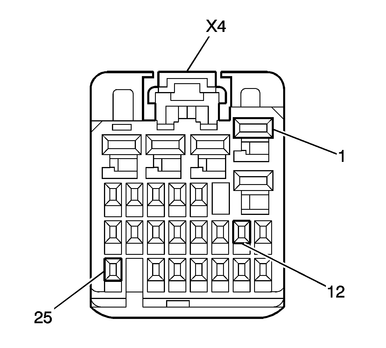
| 12.6. | Locate cavity 12 in the BCM connector X4 (black in color, 25 cavities) as shown in the graphic above. |
| 12.7. | Install the yellow wire (circuit 5187) with terminal SNAC3-A02IT-M0.64 into cavity 12. |
| 12.8. | Seat the blue terminal locking tab and install the BCM connector X4 into the BCM module. |
| 12.9. | Install a piece of conduit 213 cm (7 ft) in length around the orange wire and yellow wire starting 31 cm (1 ft) away from the BCM. |
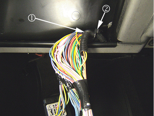
| 13.1. | Route the wires in the conduit (1) through the opening in the IP carrier and secure with a tie strap (2). |
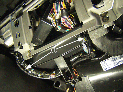
| 13.2. | Route the conduit (1) down behind the case bracket while securing the conduit to the IP harness with two tie straps. |
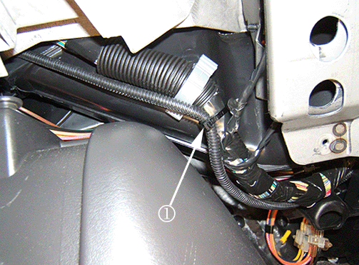
| 13.3. | Route the conduit up above the engine cover along the right side of the air duct while attaching the conduit to the main IP harness with a tie strap (1). |
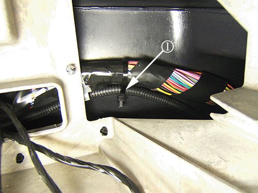
| 13.4. | Continue to route the conduit up behind the radio and secure with a tie strap (1) to the IP harness. |
| 13.5. | Route the conduit down toward the driver's floor following the accelerator harness. |
| 13.6. | Pull the driver's side of the front floor carpet or rubber mat back. |
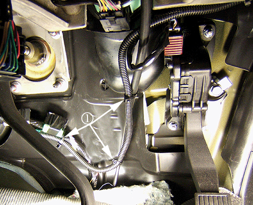
| 13.7. | The conduit routing is critical and should be routed behind the shifter cable and properly secured to the shifter cable with tie straps (1). |
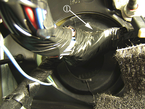
| 13.8. | Follow the front floor harness until you get to the left front main harness pass-thru grommet (1). The orange wire and yellow wire will be pushed through the grommet and installed in the UBEC later. |
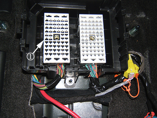
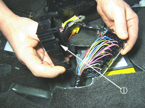
| 22.1. | Obtain a light green 16 (1.0 m) gauge wire and cut the wire to 201 cm (6 ½ ft) in length. |
| 22.2. | Add terminal 8100-4444 from the Sumitomo tray 22 to one end of the light green wire. Refer to Repairing Connector Terminals in SI. |
BBEC Connector X1
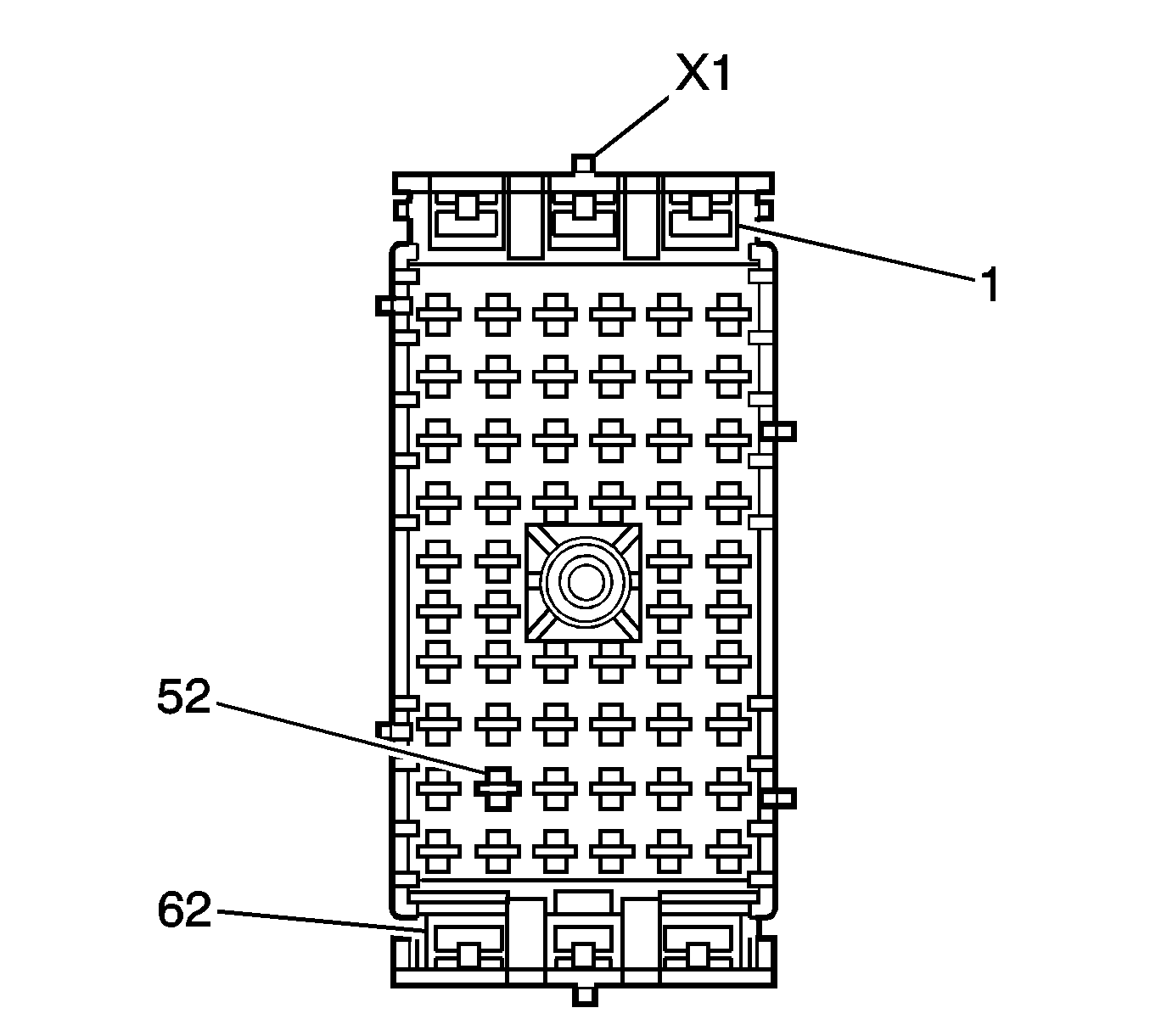
| 22.3. | Locate cavity 52 in the BBEC connector X1 (black in color, 62 cavities) as shown in the graphic above. |
| 22.4. | Install the light green wire (circuit 1624) with terminal 810-4444 into cavity 52. |
| 23.1. | Obtain a brown 16 (1.0 m) gauge wire and cut the wire to 201 cm (6 ½ ft) in length. |
| 23.2. | Add terminal 8100-4444 from the Sumitomo tray 22 to one end of the brown wire (circuit 2109). Refer to Repairing Connector Terminals in SI. |
BBEC Connector X1
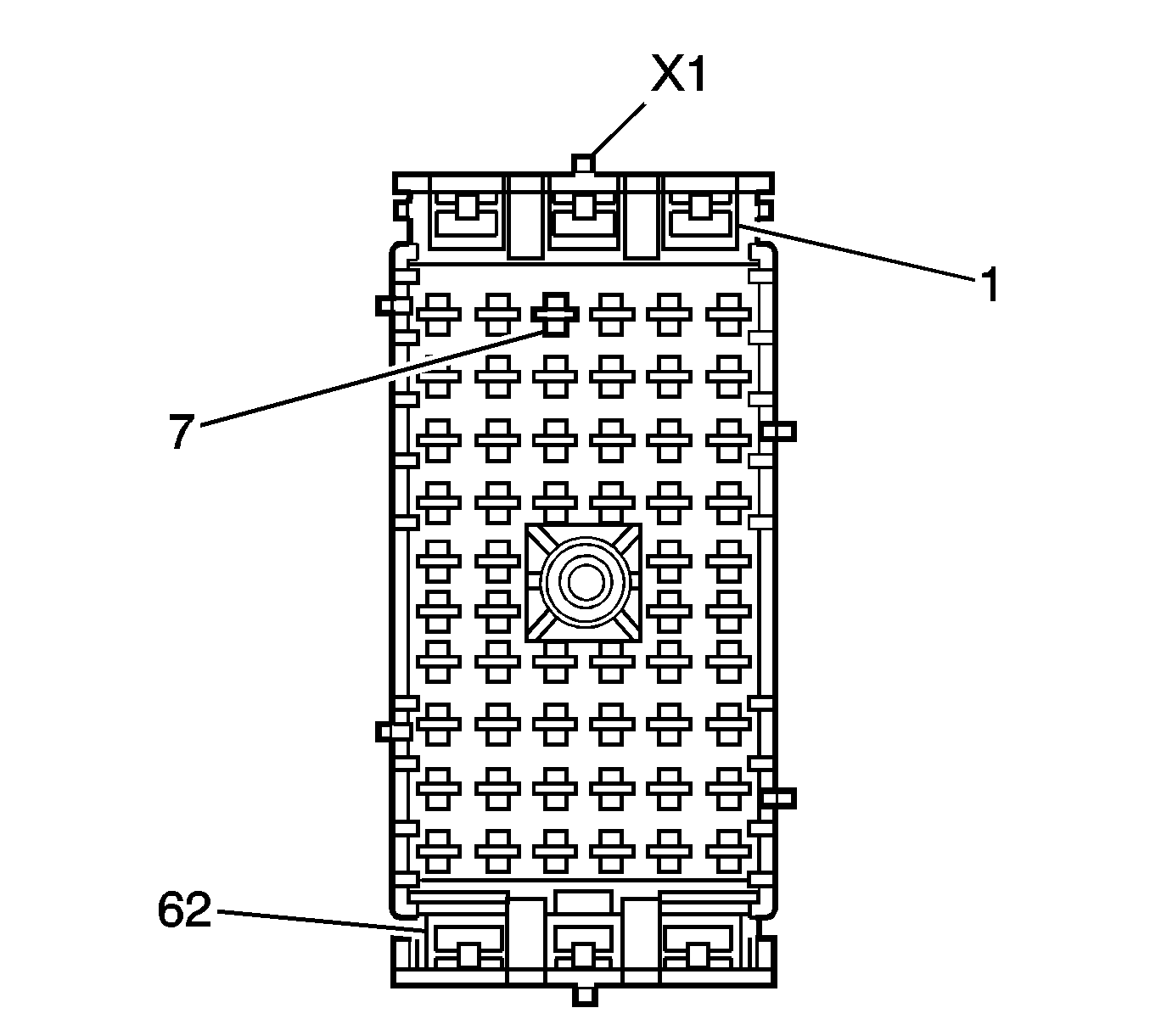
| 23.3. | Locate cavity 7 in the BBEC connector X1 (black in color, 62 cavities) as shown in the graphic above. |
| 23.4. | Install the brown wire (circuit 2109) with terminal 8100-4444 in cavity 7. |
| 28.1. | Obtain a 12 (3.0 m) gauge dark blue wire and cut the wire to 122 cm (4 ft) in length. |
| 28.2. | Leave 61 cm (2 ft) of the dark blue wire inside the vehicle, this end will be used to make up the trailer brake control module harness. |
| 28.3. | The opposite end of the dark blue wire will be pushed through the grommet and installed into the UBEC later in Step 47. |
| 29.1. | Obtain a 12 (3.0 m) gauge red/white wire and cut the wire to 122 cm (4 ft) in length. |
| 29.2. | Leave 61 cm (2 ft) of the red/white wire inside the vehicle, this end will be used to make up the trailer brake control module harness. |
| 29.3. | The opposite end of the red/white wire will be pushed through the grommet and installed into the UBEC later in Step 48. |
| 30.1. | Obtain a 20 (0.5 m) gauge light blue/white wire and cut the wire to 152 cm (5 ft) in length. |
| 30.2. | Leave 61 cm (2 ft) of the light blue/white wire inside the vehicle, this end will be used to make up the trailer brake control module harness. |
| 30.3. | The opposite end of the light blue/white wire will be pushed through the grommet and spliced into circuit 6311 later in Step 39. |
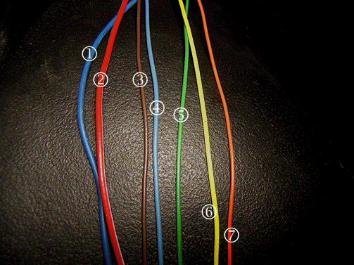
| 31.1. | Dark blue wire (circuit 47) (1) |
| 31.2. | Red/white wire (circuit 3940) (2) |
| 31.3. | Brown wire (circuit 2109) (3) |
| 31.4. | Light blue/white (circuit 6311) (4) |
| 31.5. | Light green wire (circuit 1624) (5) |
| 31.6. | Yellow wire (circuit 5187) (6) |
| 31.7. | Orange wire (circuit 5186) (7). |
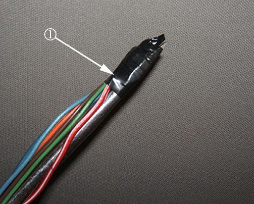
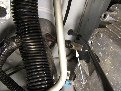
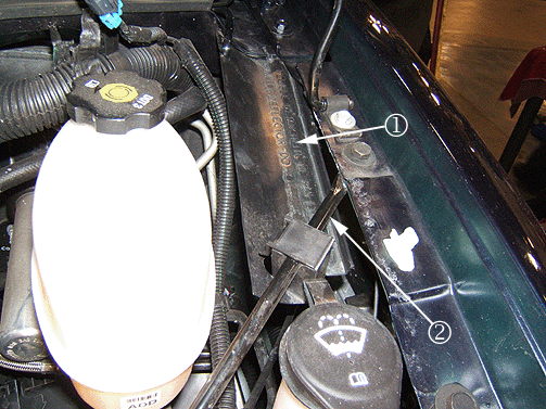
Important: It is not necessary to remove the air cleaner or any brake lines from the master cylinder if the vehicle is equipped with a diesel engine
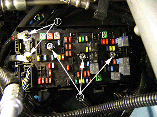
| 36.1. | Remove the junction block cover by pressing the cover tabs inward while lifting up on the cover. |
| 36.2. | Remove the battery cable nuts (1). |
| 36.3. | Remove the cables. |
| 36.4. | Loosen the three junction block bolts (2). |
| 36.5. | Remove the UBEC. |
| 36.6. | Remove the UBEC holding tray. |
| 39.1. | Remove the tape and wires from the screwdriver and route the new light blue/white wire to connector X100. |
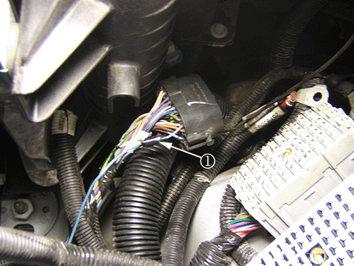
| Important: The splice clip will need to be soldered with 60/40 core solder and be properly taped and sealed. |
| 39.2. | Splice in the new light blue/white wire to the light blue/white wire (circuit 6311) located in cavity 1 of the IP engine connector X100 connector using splice clip P/N 1839906 from Delphi tray 1. Refer to Splicing Copper Wire Using Splice Clips in SI. |
| 39.3. | Tape the new light blue/white wire to the existing harness. |
UBEC Connector X3
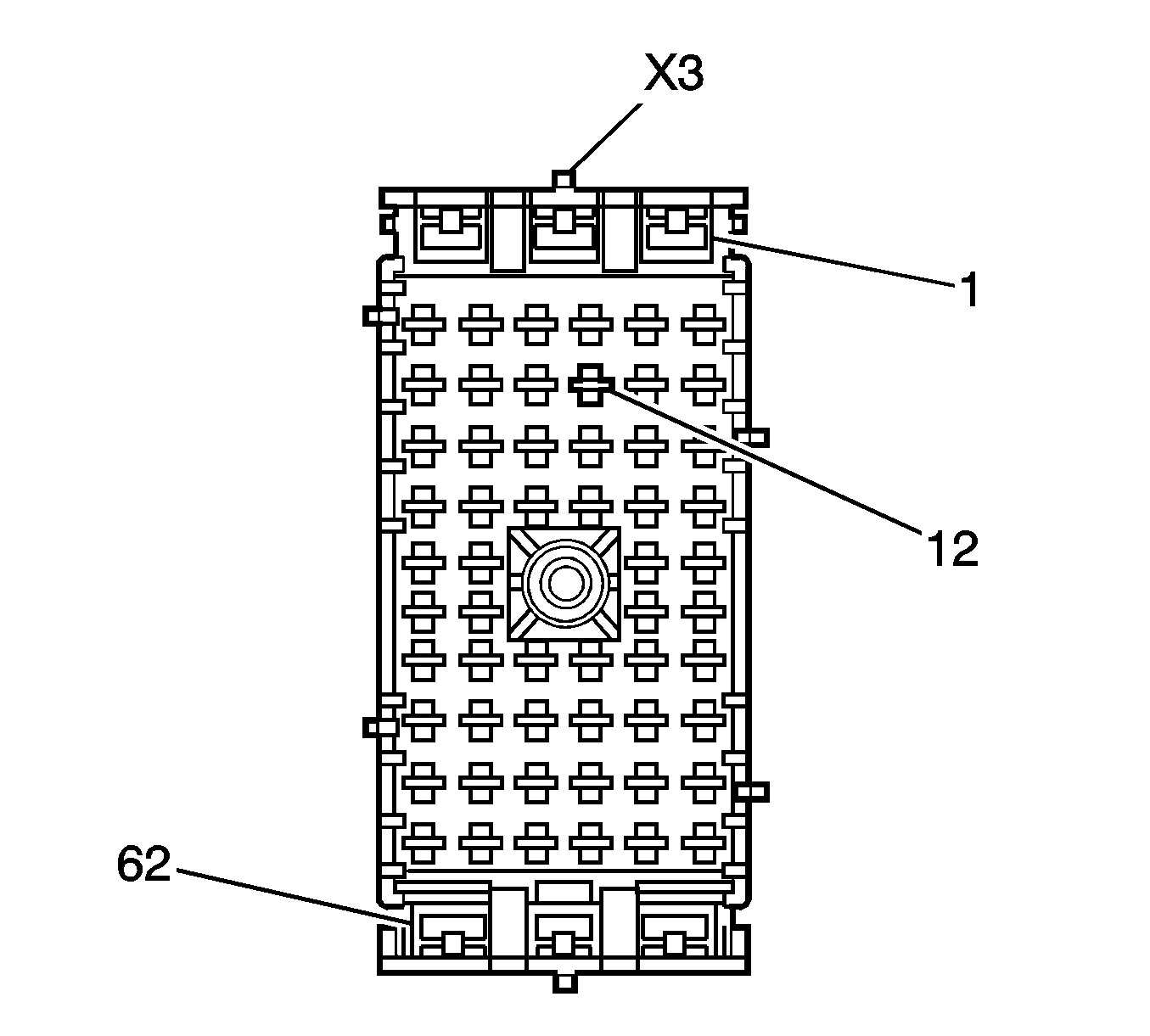
| 45.1. | Locate cavity 12 in the UBEC connector X3 (gray in color, 62 cavities) as shown in the graphic above. |
| 45.2. | Install the orange wire (circuit 5186) with terminal 8100-4443 into cavity 12. |
UBEC Connector X3
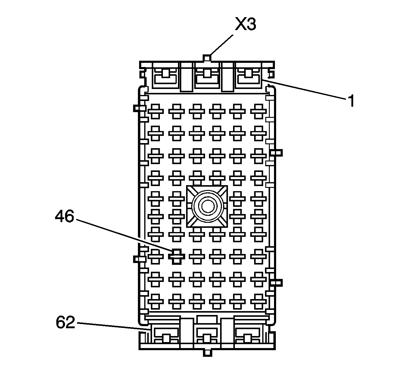
| 46.1. | Locate cavity 46 in the UBEC connector X3 (gray in color, 62 cavities) as shown in the graphic above. |
| 46.2. | Install the yellow wire (circuit 5187) with terminal 8100-4443 into cavity 46. |
UBEC Connector X3
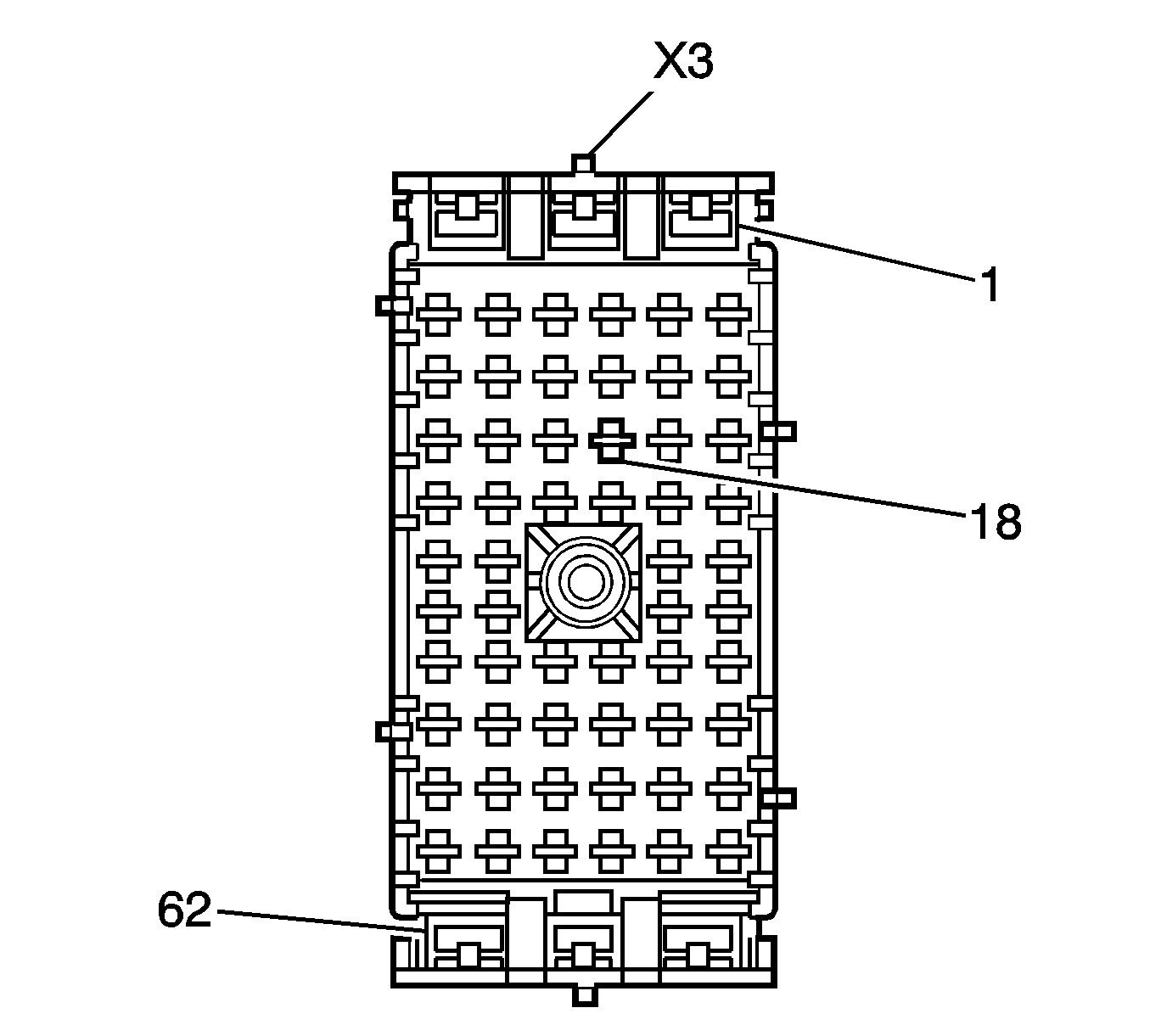
| 47.1. | Locate cavity 18 in the UBEC connector X3 (gray in color, 62 cavities) as shown in the graphic above. |
| 47.2. | Install the dark blue wire (circuit 47) with terminal 8100-4445 into cavity 18. |
UBEC Connector X3
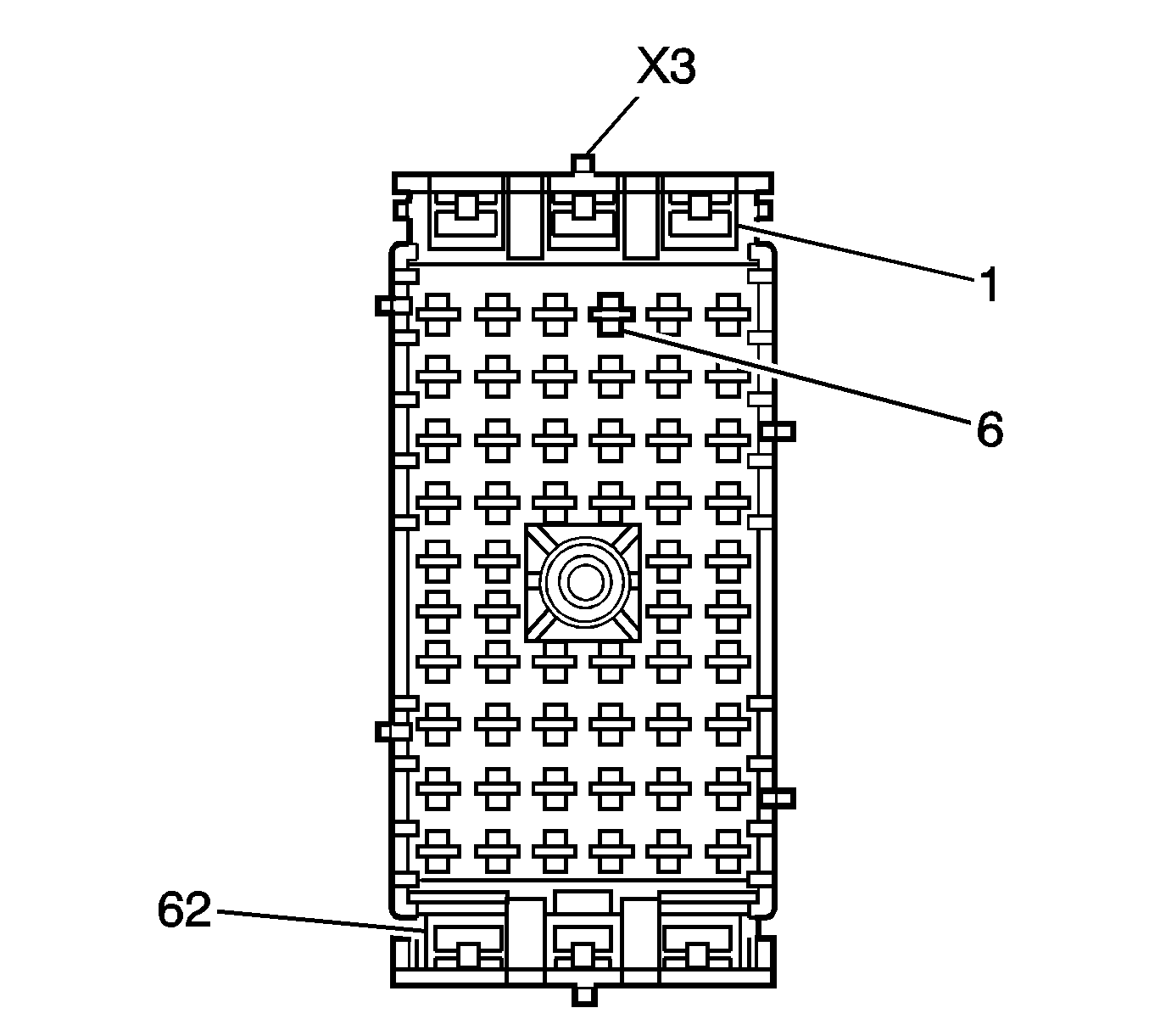
| 48.1. | Locate cavity 6 in the UBEC connector X3 (gray in color, 62 cavities) as shown in the graphic above. |
| 48.2. | Install the red/white wire (circuit 3940) with terminal 8100-4445 into cavity 6. |
UBEC Connector X3
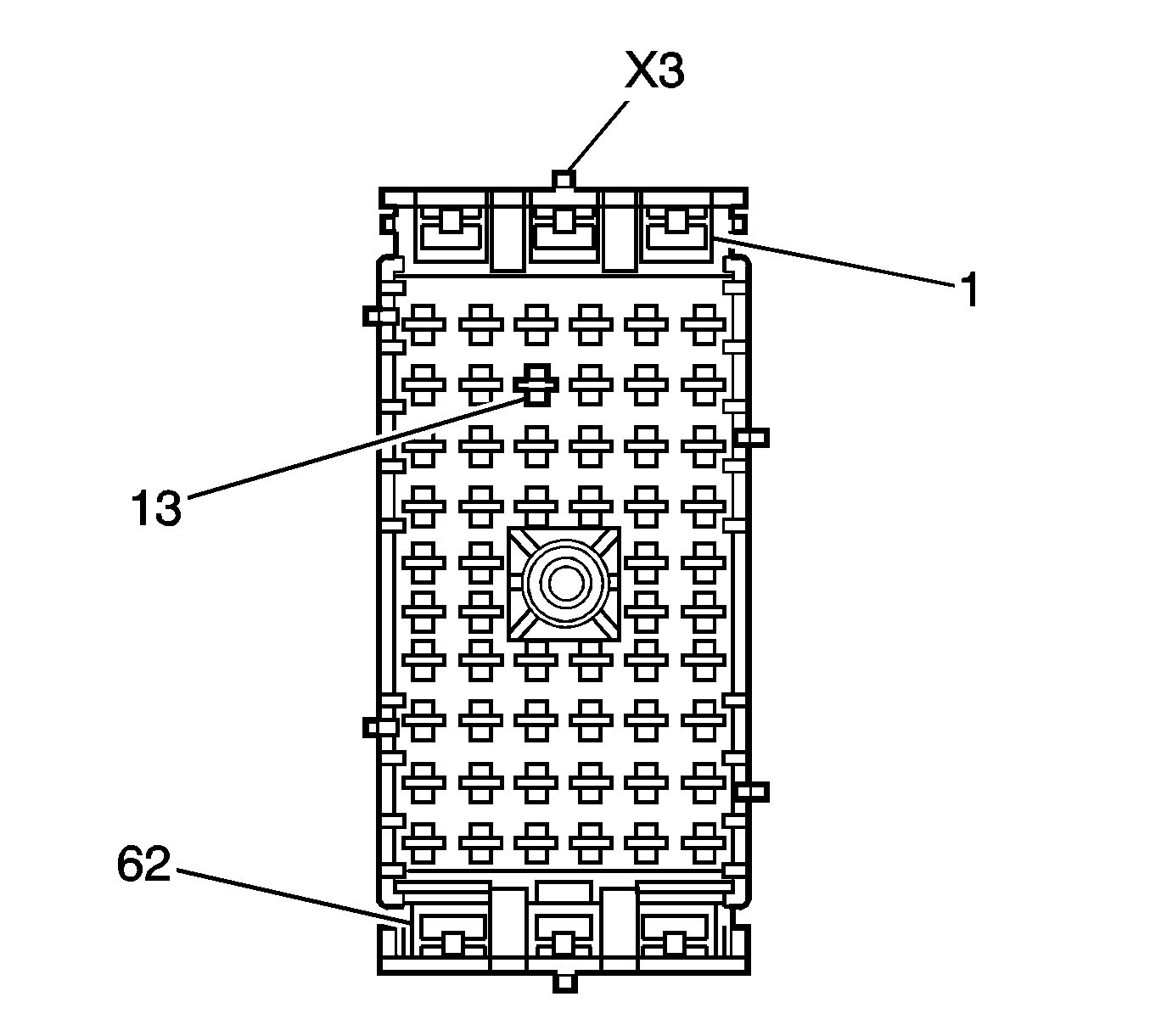
| 49.1. | Locate cavity 13 in the UBEC connector X3 (gray in color, 62 cavities) as shown in the graphic above. |
| 49.2. | Install the light green wire (circuit 1624) with terminal 8100-444 into cavity 13. |
UBEC Connector X3
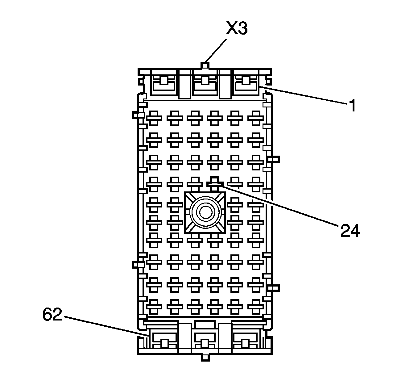
| 50.1. | Locate cavity 24 of the UBEC connector X3 (gray in color, 62 cavities) as shown in the graphic above. |
| 50.2. | Install the brown wire (circuit 2109) with terminal 8100-4444 into cavity 24. |
Install the UBEC junction block top cover.
Tighten
Tighten the brake master cylinder nuts to 36 N·m(27 lb ft).
Tighten
Tighten the support bolts to 25 N·m(18 lb ft).
| 60.1. | Obtain a 20 (0.5 m) gauge black wire and cut the wire to 91 cm (3 ft) in length. |
| 60.2. | Attach a ground ring terminal P/N 12089496 from Delphi tray 5 to one end of the black wire. Refer to Repairing Connector Terminals in SI. |
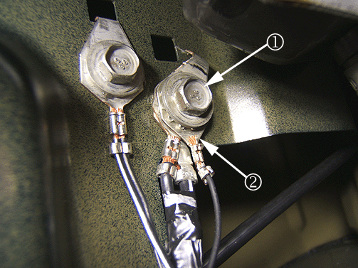
| Caution: Do not attach the new ground ring terminal to the SDM ground. Attach the new ground ring terminal (2) to the left A-pillar ground containing circuits 350 and 351. The 350 circuit can be easily identified by the 20 (0.5 m) gauge wire size. |
| 60.3. | Remove the front ground bolt (1). |
| 60.4. | Install the ground ring terminal (2) to the existing ground terminals. Refer to Repairing Connector Terminals in SI. |
| 60.5. | Tighten the ground bolt. |
Tighten
Tighten the ground bolt to 10 N·m(88 lb in).
| 60.6. | The opposite end of the black wire (circuit 350) will remain inside the vehicle and be used to make up the trailer brake control module harness. |
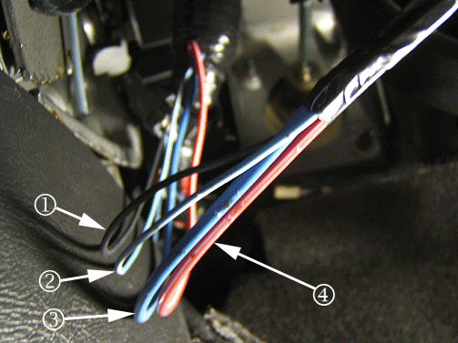
Important: A description on the location of the trailer brake control module wires may be found in the owner's manual.
| 61.1. | One black wire (circuit 350) (1) |
| 61.2. | One light blue/white wire (circuit 6311) (2) |
| 61.3. | One dark blue wire (circuit 47) (3). |
| 61.4. | One red/white wire (circuit 3940) (4) |
The chart listed below updates the information found on page 4-42 in the owner's manual regarding the four-wire harness (without connector).
| - | Wire Color: Black / Description: Ground / Circuit: 350 |
| - | Wire Color: Light Blue/White / Description: CHMSL/Stop Lamp Supply Voltage / Circuit: 6311 |
| - | Wire Color: Dark Blue / Trailer Feed Auxiliary Circuit / Circuit: 47 |
| - | Wire Color: Red/White / Description: Battery Feed / Circuit: 3940 |
If the vehicle is equipped with the auxiliary battery, reconnect the negative battery cable.
Courtesy Transportation
The General Motors Courtesy Transportation program is intended to minimize customer inconvenience when a vehicle requires a repair that is covered by the New Vehicle Limited Warranty. The availability of courtesy transportation to customers whose vehicles are within the warranty coverage period and involved in a product program is very important in maintaining customer satisfaction. Dealers are to ensure that these customers understand that shuttle service or some other form of courtesy transportation is available and will be provided at no charge. Dealers should refer to the General Motors Service Policies and Procedures Manual for Courtesy Transportation guidelines.
Claim Information
Submit a Product Claim with the information indicated below:
Repair Performed | Part Count | Part No. | Parts Allow | CC-FC | Labor Op | Labor Hours | Net Item |
|---|---|---|---|---|---|---|---|
Add Trailer Wiring Circuits and Trailer Brake Control Module Harness | 10 | -- | * | MA-96 | V1776 | 5.2 | ** |
Add Time for Additional Upfitter Equipment | 0.1-1.0*** | ||||||
Courtesy Transportation for vehicles within the New Vehicle Limited Warranty (US & Canadian GM Dealers) | N/A | N/A | N/A | MA-96 | **** | N/A | ***** |
* The "Parts Allowance" should be the sum total of the current GMSPO Dealer net price plus applicable Mark-Up for the tie straps needed to complete the repair. ** The amount identified in the "Net Item" column should represent the actual sum total of the current GMSPO Dealer net price plus applicable Mark-Up for the 7 feet conduit needed to perform the required repairs, plus $64.50 USD, for the wire and terminals needed to perform the required repair. *** If add labor hours exceed 1.0 hours, AVM approval is required. **** Submit courtesy transportation using normal labor operations for courtesy transportation as indicated in the GM Service Policies and Procedures Manual for vehicles within the New Vehicle Limited Warranty. ***** The amount identified in the "Net Item" column should represent the actual dollar amount for courtesy transportation. | |||||||
Refer to the General Motors WINS Claims Processing Manual for details on Product Recall Claim Submission.
Customer Notification
General Motors will notify customers of this program on their vehicle (see copy of customer letter included with this bulletin).
Dealer Recall Responsibility
All unsold new vehicles in dealers' possession and subject to this program must be held and inspected/repaired per the service procedure of this program bulletin before customers take possession of these vehicles.
Dealers are to service all vehicles subject to this program at no charge to customers, regardless of mileage, age of vehicle, or ownership, through February 28, 2009.
Customers who have recently purchased vehicles sold from your vehicle inventory, and for which there is no customer information indicated on the dealer listing, are to be contacted by the dealer. Arrangements are to be made to make the required correction according to the instructions contained in this bulletin. A copy of the customer letter is provided in this bulletin for your use in contacting customers. Program follow-up cards should not be used for this purpose, since the customer may not as yet have received the notification letter.
In summary, whenever a vehicle subject to this program enters your vehicle inventory, or is in your dealership for service prior to February 28, 2009, you must take the steps necessary to be sure the program correction has been made before selling or releasing the vehicle.
February 2008Dear General Motors Customer:
We have learned that your 2008 model year Chevrolet Express or GMC Savana vehicle, equipped with a trailer wiring harness and an upfitter recreational vehicle package, may have a condition in which a wiring harness may be missing circuits. Without these circuits, the trailer lights will not illuminate.
Your satisfaction with your 2008 model year Chevrolet Express or GMC Savana vehicle is very important to us, so we are announcing a program to correct this condition.
What We Will Do:
To correct this condition, your GM dealer will install the missing circuits. This service will be performed for you at no charge until February 28, 2009.
What You Should Do:
To limit any possible inconvenience, we recommend that you contact your dealer as soon as possible to schedule an appointment for this repair. By scheduling an appointment, your dealer can ensure that the necessary parts will be available on your scheduled appointment date.
Customer Reply Form: The enclosed customer reply form identifies your vehicle. Presentation of this form to your dealer will assist in making the necessary correction in the shortest possible time. If you no longer own this vehicle, please let us know by completing the form and mailing it back to us.
If you have any questions or need any assistance, just contact your dealer or the appropriate Customer Assistance Center at the number listed below. The Customer Assistance Center’s hours of operation are from 8:00 AM to 11:00 PM, EST, Monday through Friday.
Division | Number | Text Telephones (TTY) |
|---|---|---|
Chevrolet | 1-800-630-2438 | 1-800-833-2438 |
GMC | 1-866-996-9463 | 1-800-462-8583 |
Guam | 1-671-648-8450 |
|
Puerto Rico - English | 1-800-496-9992 |
|
Puerto Rico - Español | 1-800-496-9993 |
|
Virgin Islands | 1-800-496-9994 |
|
Courtesy Transportation:
If your vehicle is within the New Vehicle Limited Warranty your dealer may provide you with shuttle service or some other form of courtesy transportation while your vehicle is at the dealership for this repair. Please refer to your Owner’s Manual and your dealer for details on Courtesy Transportation.
We sincerely regret any inconvenience or concern that this situation may cause you. We want you to know that we will do our best, throughout your ownership experience, to ensure that your GM vehicle provides you many miles of enjoyable driving.
Scott Lawson
General Director,
Customer and Relationship Services
Enclosure
07335
