Special Tools
J 41427 Engine Lift Brackets
Removal Procedure
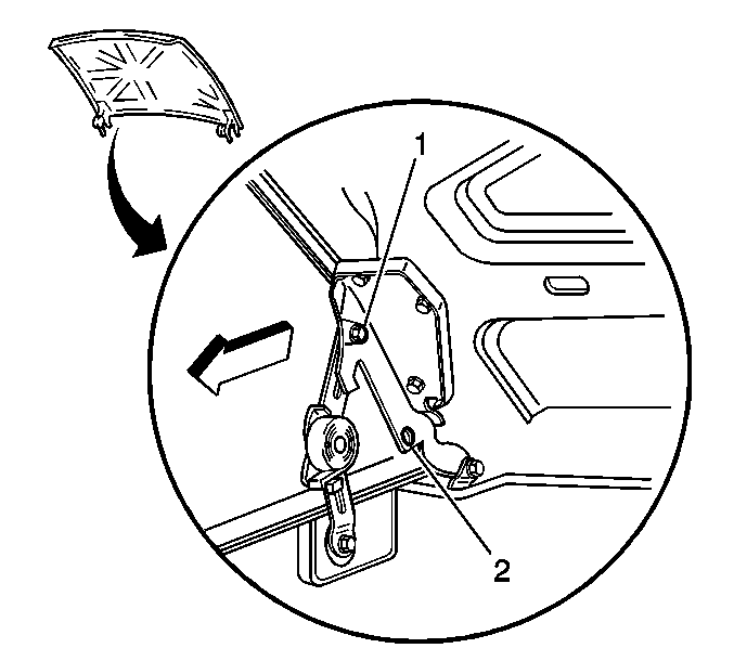
- Raise the hood to the service position, perform the following:
| 1.1. | Remove the hood hinge bolts (1). |
| 1.2. | Raise the hood until vertical. |
| 1.3. | Install the hood hinge bolts until snug in the service position (2). |
- Disconnect the negative battery cable. Refer to
Battery Negative Cable Disconnection and Connection.
- Remove the cooling layer. Refer to
Cooling Layer Removal.
- Drain the cooling system. Refer to
Cooling System Draining and Filling.
- Remove the fuel pipes/hoses. Refer to
Fuel Hose/Pipes Replacement - Engine Compartment.
- Remove the lower fan shroud. Refer to
Engine Coolant Fan Lower Shroud Replacement.
- Remove the drive belt. Refer to
Drive Belt Replacement.
- Raise and suitably support the vehicle. Refer to
Lifting and Jacking the Vehicle.
- Remove the starter. Refer to
Starter Motor Replacement.
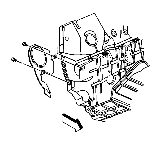
- Remove the transmission cover.
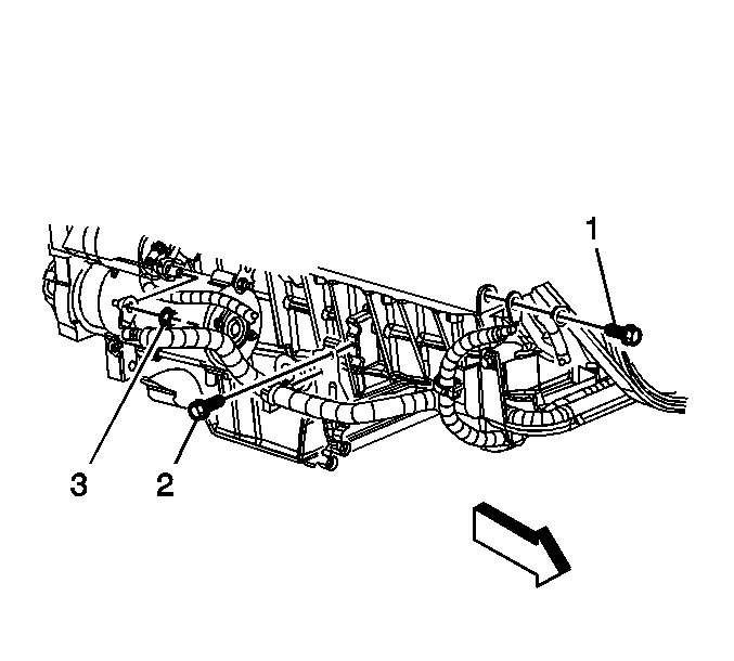
- Remove the positive battery cable clip bolt (2).
- Remove the catalytic converter. Refer to
Catalytic Converter Replacement.
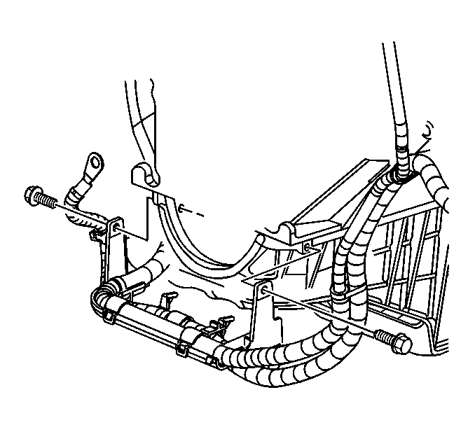
- Remove the battery cable bracket bolts.
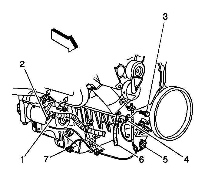
- Disconnect the crankshaft position (CKP) sensor electrical connector (5) and remove the harness from the retainer clip.
- Remove the ground bolt (3) holding the negative battery cable (6) and ground cable (4) to the engine.
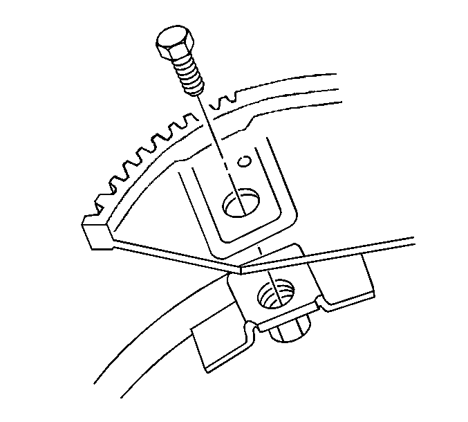
- If equipped, remove the torque converter bolts.
- Remove the transmission bolts.
- Lower the vehicle.
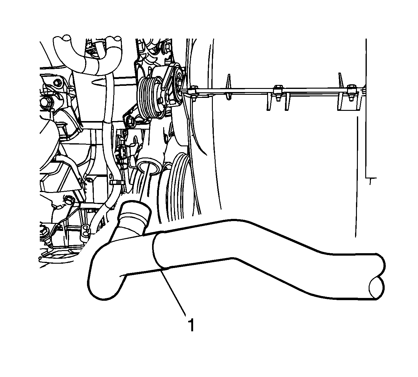
- Reposition the radiator outlet hose clamps.
- Remove the radiator outlet hose (1) from the water pump.
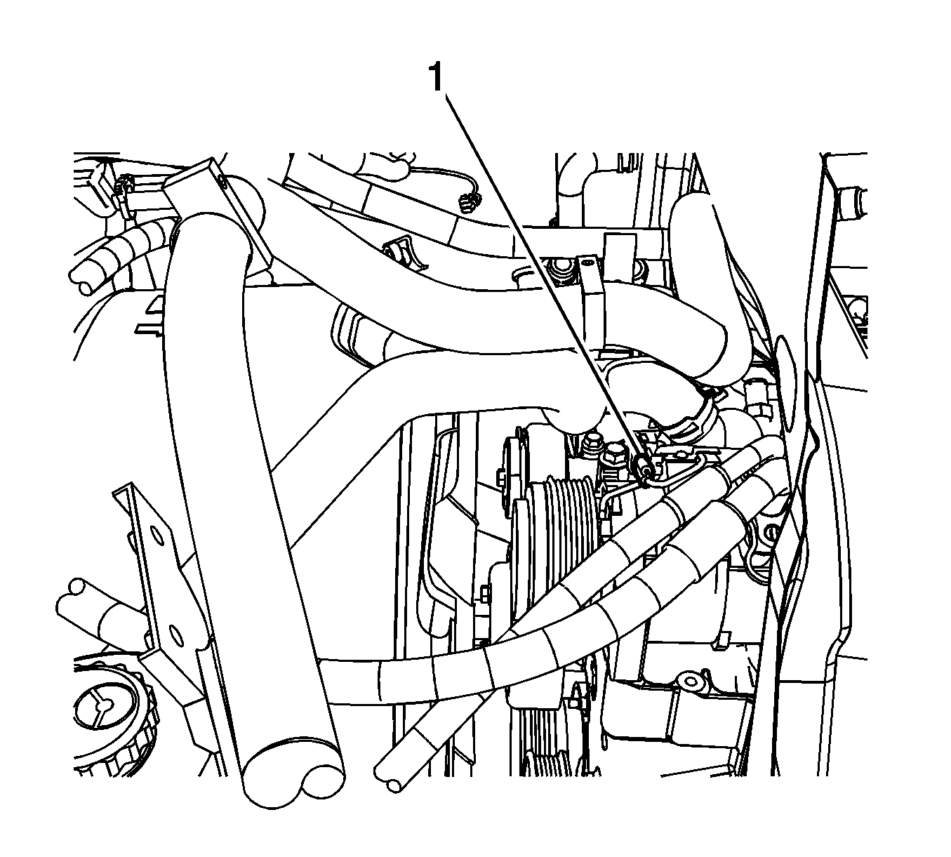
- Disconnect the air conditioning (A/C) compressor clutch (1), if equipped
- If equipped, remove the air conditioning (A/C) hoses. Refer to
Discharge Hose Replacement and
Suction Hose Replacement.
- Remove the positive cable nut and cable from the generator.
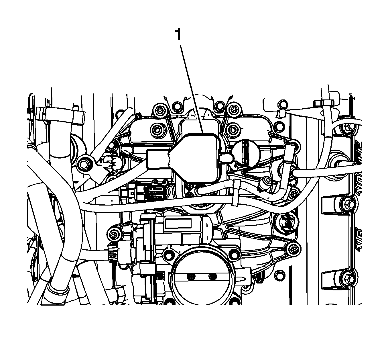
- Disconnect the control port injector module (1).
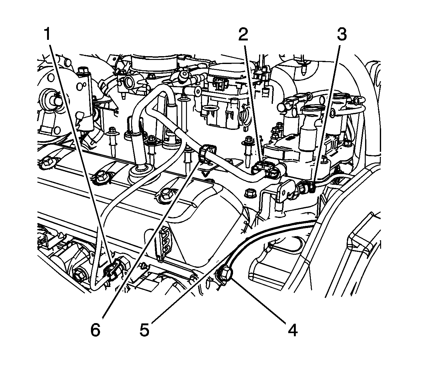
- Disconnect the following electrical connectors:
| • | Engine coolant temperature sensor (1) |
| • | Oil pressure sensor (3) |
- Remove the harness ground bolt (4).
- Reposition the harness ground (5).
- Remove the ignition coil wiring harness clip (6) from the engine wiring bracket.
- Unclip the ignition coil wiring harness from the fuel feed pipe.
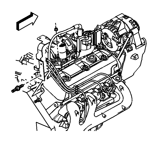
- Remove the engine wiring harness rear bracket nut at the EVAP canister purge solenoid valve.
- Remove the stud holding the engine wiring harness bracket.
- Reposition the engine wiring harness with the bracket aside.
- Remove the heater hoses. Refer to
Heater Inlet Hose Replacement and
Heater Outlet Hose Replacement.
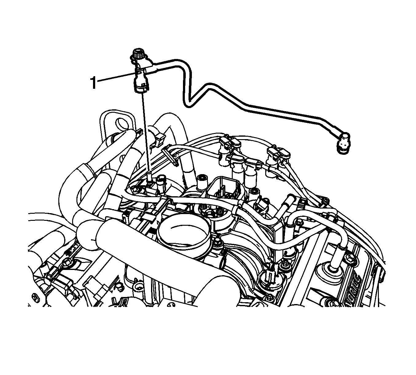
- Disconnect the EVAP canister harness (1) from the purge solenoid valve.
- Disconnect the power brake booster vacuum hose from the vacuum fitting.
- Remove the thermostat and water outlet. Refer to
Engine Coolant Thermostat Replacement.
- Remove the lower intake manifold. Refer to
Lower Intake Manifold Replacement.
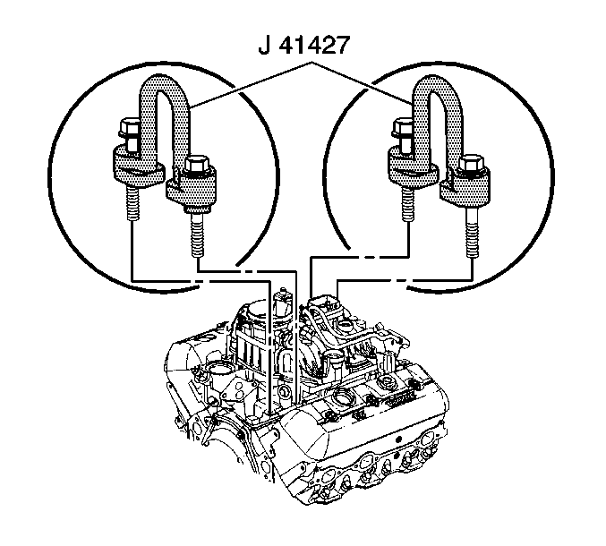
- Remove the left front and right rear intake manifold lower bolts.
- Install
J 41427 to the left front and right rear intake manifold bolts, using the following procedure:
| 39.1. | Install the
J 41427 marked RIGHT REAR. |
Caution: Refer to Fastener Caution in the Preface section.
| 39.2. | Install the lift bracket bolts and tighten to
15 N·m (11 lb ft). |
| 39.3. | Install the
J 41427 marked LEFT FRONT with the arrow pointing to the front of the engine. |
| 39.4. | Install the lift bracket bolts and tighten to
15 N·m (11 lb ft). |
- Install a suitable lifting devise to the engine lift brackets.
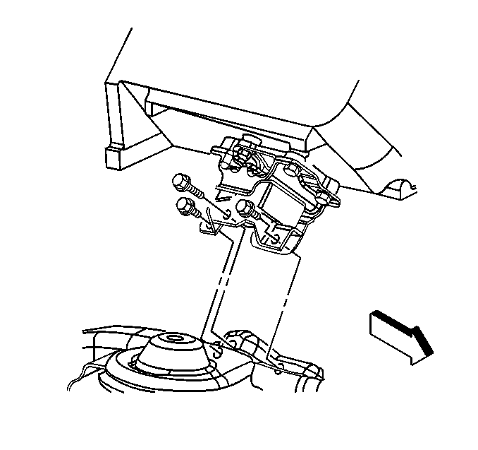
- Remove the engine mount to engine mount bracket nuts.
- Support the transmission with a suitable floor jack.
- Remove the engine.
Installation Procedure

- Install the engine.
- Install the engine mount to engine mount bracket bolts and tighten to
65 N·m (48 lb ft).

- Remove the lifting devise and the
J 41427 .
- Install the lower intake manifold. Refer to
Lower Intake Manifold Replacement.
- Install one transmission bolt until snug.
- Remove the support jack from under the transmission.
- Install the thermostat and water outlet. Refer to
Engine Coolant Thermostat Replacement.

- Connect the power brake booster vacuum hose to the vacuum fitting.
- Connect the EVAP canister harness (1) to the purge solenoid valve.
- Install the heater hoses. Refer to
Heater Inlet Hose Replacement and
Heater Outlet Hose Replacement.

- Position the engine wiring harness.
- Install the stud holding the engine wiring harness bracket.
- Install the engine wiring harness rear bracket nut at the EVAP canister purge solenoid valve and tighten to
9 N·m (80 lb in).

- Reposition the harness ground (5).
- Install the harness ground bolt (4) and tighten to
16 N·m (12 lb ft).
- Connect the following electrical connectors:
| • | Oil pressure sensor (3) |
| • | Engine coolant temperature sensor (1) |
- Install the ignition coil harness retaining clip (6) into the engine wiring harness bracket.

- Connect the control port injector module (1).

- If equipped, install the A/C hoses. Refer to
Discharge Hose Replacement and
Suction Hose Replacement.
- Connect the A/C compressor clutch (1), if equipped.

- Install the radiator outlet hose (1) to the water pump.
- Position the radiator outlet hose clamps.
- Install the drive belt. Refer to
Drive Belt Replacement.
- Install the lower fan shroud. Refer to
Engine Coolant Fan Lower Shroud Replacement.
- Install the fuel pipes/hoses. Refer to
Fuel Hose/Pipes Replacement - Engine Compartment.

- Remove the hood hinge bolt from the service position (2).
- Lower the hood to the normal position.
- Install the hood hinge bolts and tighten to
25 N·m (18 lb ft).
- Raise the vehicle.

- Install the transmission bolts and tighten to
50 N·m (37 lb ft).
- If equipped, install the torque converter bolts and tighten to
63 N·m (47 lb ft).

- Install the ground bolt (3) holding the negative battery cable (6) and ground cable (4) to the engine.
- Connect the CKP sensor electrical connector (5) and install the harness to the retainer clip.

- Install the battery cable bracket bolts and tighten to
12 N·m (106 lb in).
- Install the catalytic converter. Refer to
Catalytic Converter Replacement.

- Install the positive battery cable clip bolt (2).

- Install the transmission cover and tighten the bolts to
12 N·m (106 lb in).
- Install the starter. Refer to
Starter Motor Replacement.
- Lower the vehicle.
- Install the cooling layer. Refer to
Cooling Layer Installation.
- Connect the negative battery cable. Refer to
Battery Negative Cable Disconnection and Connection.
- Perform the engine prelube procedure. Refer to
Engine Prelubing.
- Add engine oil supplement to the engine oil. Refer to
Adhesives, Fluids, Lubricants, and Sealers for the correct part number.
- Disable the ignition system.
- Crank the engine several times. Listen for any unusual noises or evidence that parts are binding.
- Start the engine and listen for unusual noises.
- Check the oil pressure gauge or light and confirm that the engine has acceptable oil pressure.
- If necessary, install an oil pressure gage and measure the oil pressure.
- Run the engine speed at about 1,000 RPM until the engine has reached normal operating temperature.
- Listen for sticking valve lifters, or other unusual noises.
- Inspect for fuel, oil, and/or coolant leaks while the engine is running.
- Perform a final inspection for the proper oil and coolant levels.
- Close the hood.


