Rear Brake Caliper Replacement With Single Rear Wheel
Removal Procedure
Warning: Refer to Brake Dust Warning in the Preface section.
Warning: Refer to Brake Fluid Irritant Warning in the Preface section.
- Inspect the fluid level in the brake master cylinder reservoir.
- If the brake fluid level is midway between the maximum-full point and the minimum allowable level then no brake fluid needs to be removed from the reservoir before proceeding.
- If the brake fluid level is higher than midway between the maximum-full point and the minimum allowable level then remove brake fluid to the midway point before proceeding.
- Raise and support the vehicle. Refer to Lifting and Jacking the Vehicle.
- Remove the tire and wheel assembly. Refer to Tire and Wheel Removal and Installation.
- Compress the brake caliper pistons.
- Clean all dirt and foreign material from the brake hose end.
- Remove the brake hose to caliper bolt from the brake caliper.
- Remove and discard the 2 copper brake hose gaskets. These gaskets may be stuck to the brake caliper housing or the brake hose end.
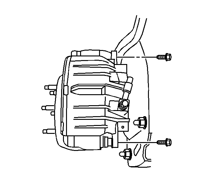
- Remove the caliper guide pin bolts.
- Remove the brake caliper from the vehicle.
- Inspect the caliper assembly. Refer to Brake Caliper Inspection.
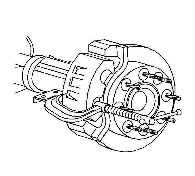
| • | Install a large C-clamp over the top of the caliper housing and against the back of the outboard pad. |
| • | Slowly tighten the C-clamp until the pistons are pushed completely into the caliper bores. |
| • | Remove the C-clamp from the caliper. |
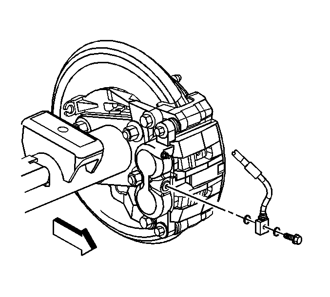
Note: Install a rubber cap or plug to the exposed brake pipe fitting end to prevent brake fluid loss and contamination.
Installation Procedure
- If you are installing new brake pads use a C-clamp in order to compress the pistons to the bottom of the caliper bores. Use the old brake pad, a metal plate or a wooden block across the face of the pistons in order to protect the pistons and the caliper boots.
- Ensure that the caliper boots are below the level of the face of both pistons.
- Install the brake caliper to the brake caliper mounting bracket.
- Perform the following procedure before installing the caliper guide pin bolts.
- Install the brake caliper mounting bolts.
- Tighten the brake caliper guide pin bolts - rear.
- Remove the rubber cap or plug from the exposed brake hose fitting end.
- Assemble the 2 NEW copper brake hose gaskets and the brake hose to caliper bolt to the brake hose.
- Install the brake hose assembly to the brake caliper and tighten to 44 N·m (32 lb ft).
- Bleed the hydraulic brake system. Refer to Hydraulic Brake System Bleeding.
- Install the tire and wheel assembly. Refer to Tire and Wheel Removal and Installation.
- Lower the vehicle.
- Fill the master cylinder reservoir to the proper level with clean brake fluid. Refer to Master Cylinder Reservoir Filling.
Note: Use denatured alcohol to clean the outside surface of caliper boots before installing new brake pads.
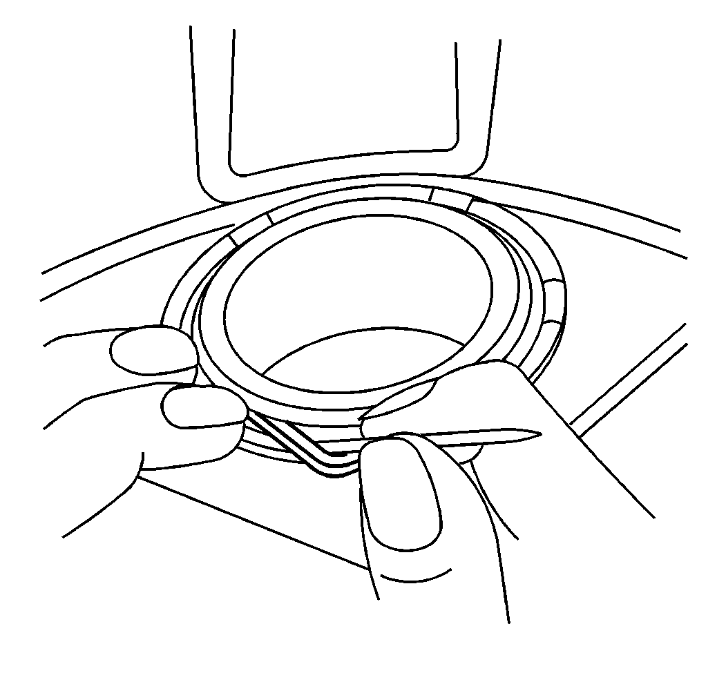
Note: Use a small flat-bladed tool and lift the inner edge of the caliper boots next to both pistons to release any trapped air.
| 4.1. | Remove all traces of the original adhesive patch. |
| 4.2. | Clean the threads of the bolt with brake parts cleaner or the equivalent and allow to dry. |
| 4.3. | Apply threadlocker GM P/N 12345493 (Canadian P/N 10953488) to the threads of the bolt. |

Caution: Refer to Fastener Caution in the Preface section.
| • | Tighten the bolts to 34 N·m (25 lb ft) (JH5). |
| • | Tighten the bolts to 72 N·m (53 lb ft) (JH6, JH7). |
Note: Install 2 NEW copper brake hose gaskets.

Rear Brake Caliper Replacement Dual Rear Wheel
Removal Procedure
Warning: Refer to Brake Dust Warning in the Preface section.
Warning: Refer to Brake Fluid Irritant Warning in the Preface section.
- Inspect the fluid level in the brake master cylinder reservoir.
- If the brake fluid level is midway between the maximum-full point and the minimum allowable level then no brake fluid needs to be removed from the reservoir before proceeding.
- If the brake fluid level is higher than midway between the maximum-full point and the minimum allowable level then remove brake fluid to the midway point before proceeding.
- Raise and support the vehicle. Refer to Lifting and Jacking the Vehicle.
- Remove the tire and wheel assembly. Refer to Tire and Wheel Removal and Installation.
- Position a large C-clamp against the outboard disc brake pad backing plate and over the rear of the brake caliper body.
- Using the C-clamp, slowly and evenly bottom the brake caliper pistons into the brake caliper bores.
- Remove the brake hose fitting bolt (1).
- Remove and discard the brake hose fitting gaskets (2) from the brake hose (3).
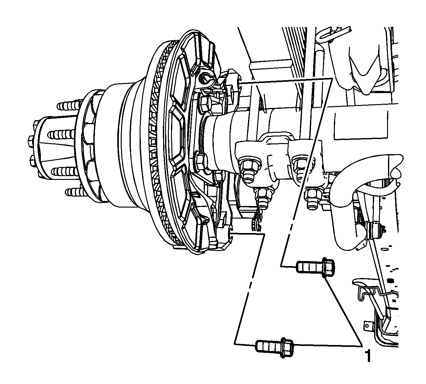
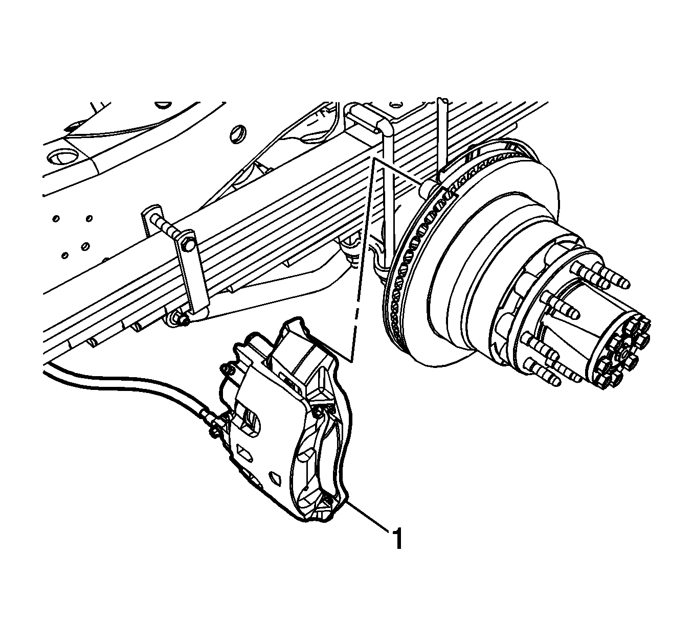
- Remove the brake caliper bracket bolts (1).
- Remove the brake caliper and bracket assembly.
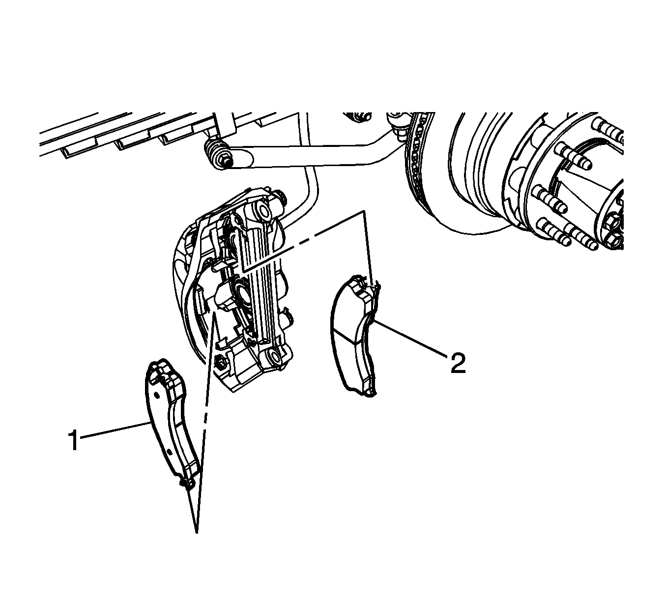
- Remove the outer brake pad (1).
- Remove the inner brake pad (2).
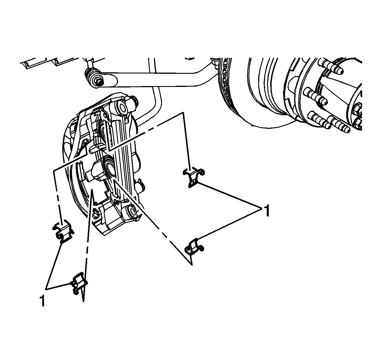
- Remove the brake pad springs (1).
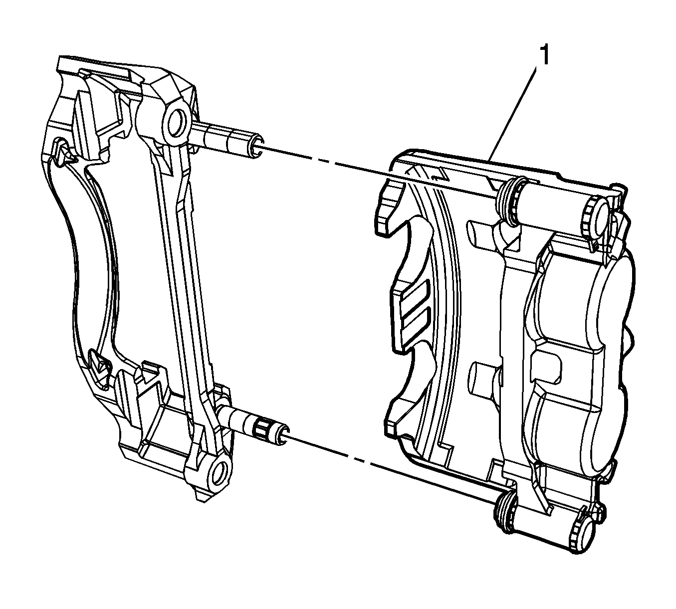
- Slide the brake caliper (1) off of the brake caliper guide pins and the caliper bracket.
- Inspect the brake caliper mounting and hardware for damage and wear. Refer to Rear Disc Brake Mounting and Hardware Inspection.
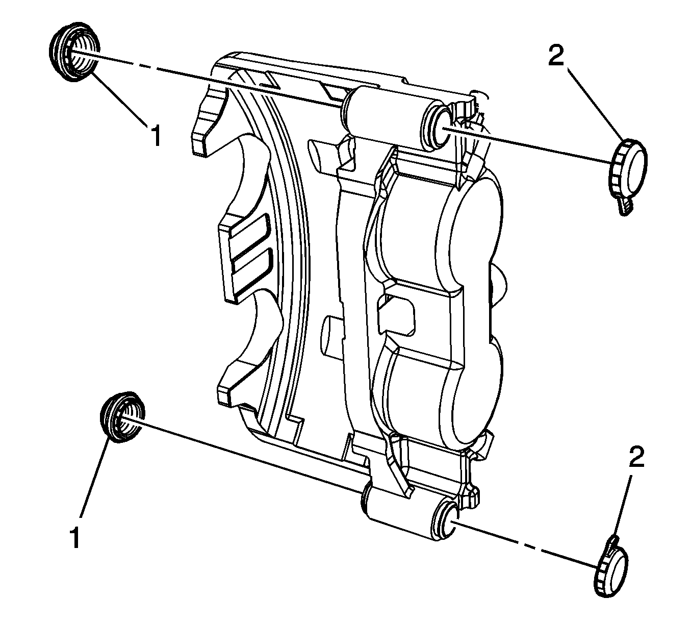
- Remove the brake caliper guide pin seals (1) and the brake caliper guide pin caps (2).
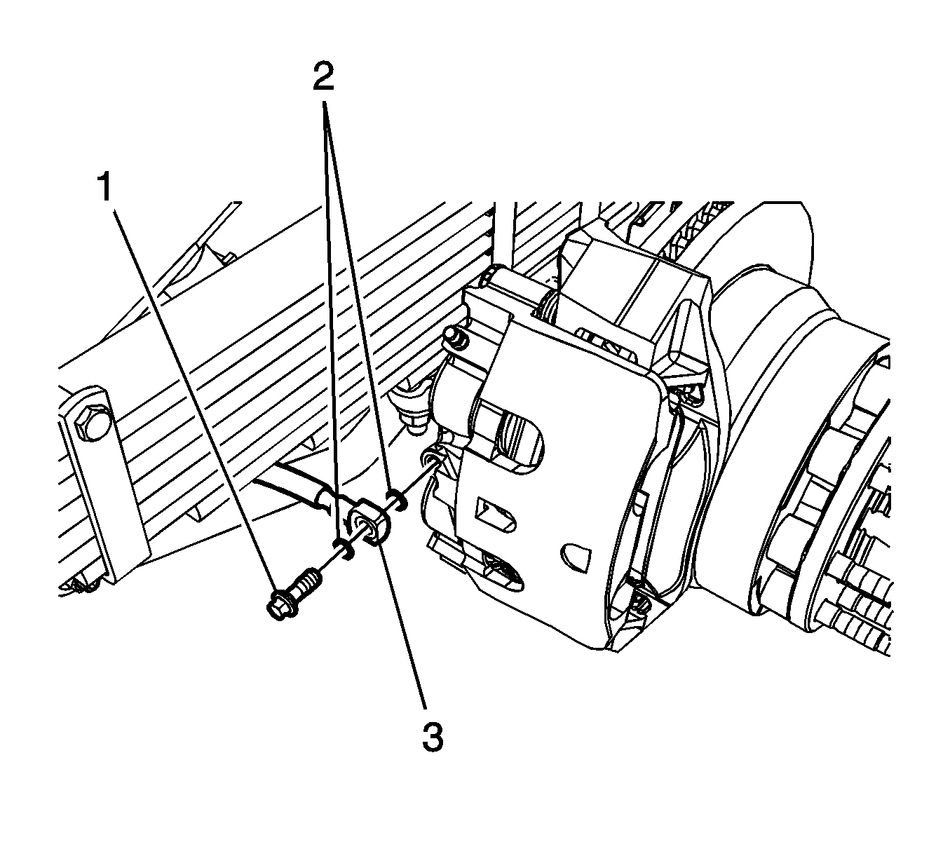
Note: Do not reuse the brake hose fitting gaskets.
Cap the brake hose fitting to prevent brake fluid loss and contamination.
Note: Do not remove the brake caliper guide pins unless replacement is required.
Installation Procedure
- Apply a light coat of high temperature silicone brake lubricant to the brake caliper guide pin bores.
- Install the brake caliper guide pin seals (1)
- Install the brake caliper guide pin caps (2).
- Slide the brake caliper (1) on to the brake caliper guide pins and the caliper bracket.
- Install the brake pad springs (1).
- Prepare the brake caliper bracket bolts and the rear axle threaded holes for assembly.
- Apply threadlocker GM P/N 89021297 (Canadian P/N 10953488) to 2/3 of the threaded length of the brake caliper bracket bolt.
- Allow the threadlocker to cure approximately 10 minutes before assembly.
- Position the brake caliper and bracket assembly (1) to the rear axle.
- Install the brake caliper bracket bolts (1) and tighten to 300N·m (221 lb ft).
- Assemble the brake hose fitting bolt (1) and 2 new brake hose fitting gaskets (2) to the brake hose (3).
- Tighten the brake hose fitting bolt to 40 N·m (30 lb ft).
- Bleed the hydraulic brake system. Refer to Hydraulic Brake System Bleeding.
- Install the tire and wheel assembly. Refer to Tire and Wheel Removal and Installation.

Ensure the brake caliper guide pin seals are fully seated in the groove of the brake caliper housing.
Ensure the brake caliper guide pin caps are fully seated in the groove of the brake caliper housing.
Note: Do not remove the brake caliper guide pins unless replacement is required.

Ensure the brake caliper guide pin seals are fully seated in the groove of the brake caliper bracket.

| • | Clean the brake caliper bracket bolts of any threadlocking residue |
| • | Clean the rear axle threaded holes of any threadlocking residue with denatured alcohol and allow to dry |
Caution: Refer to Fastener Caution in the Preface section.


