For 1990-2009 cars only
Removal Procedure
- Block the drive wheels.
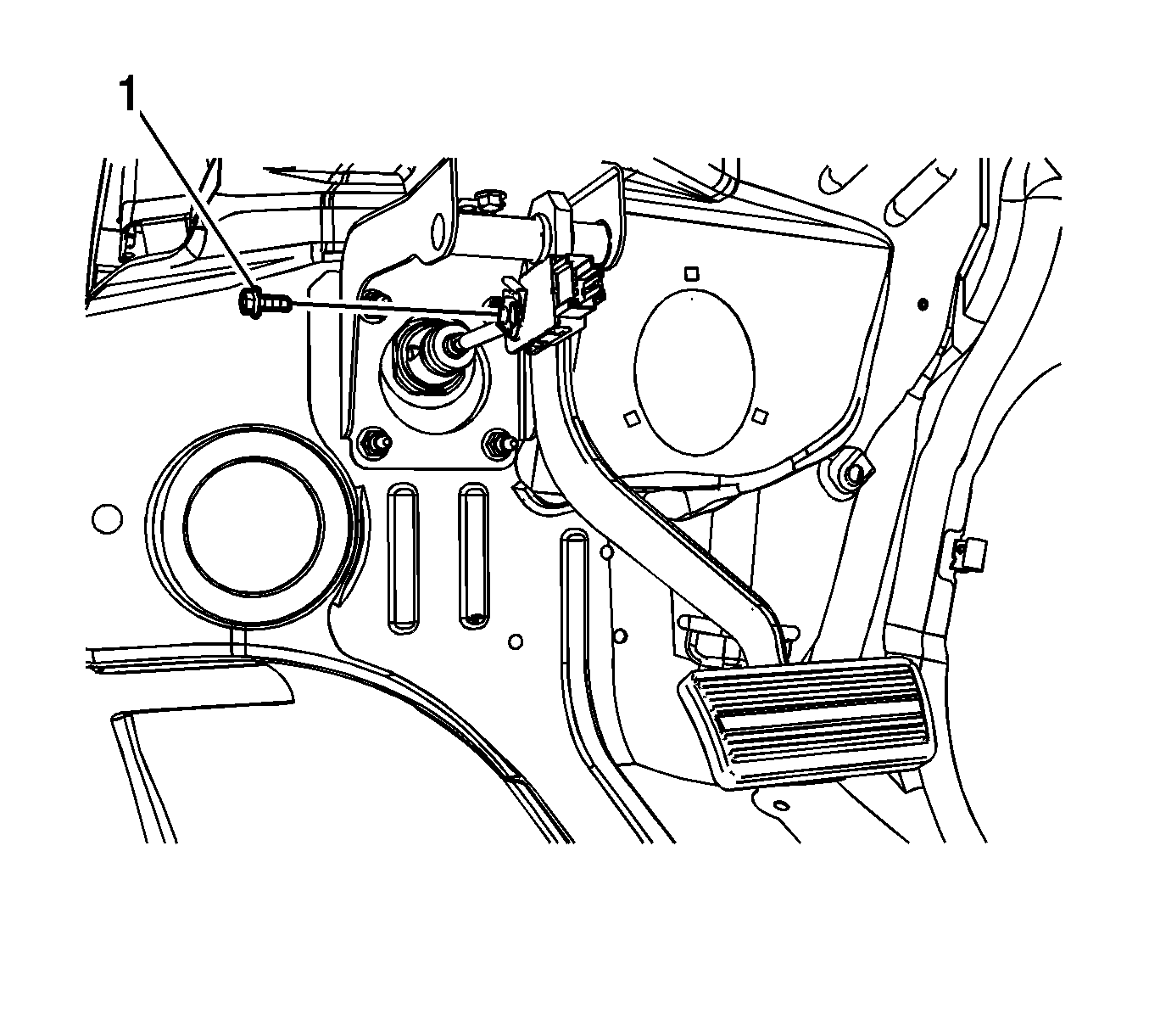
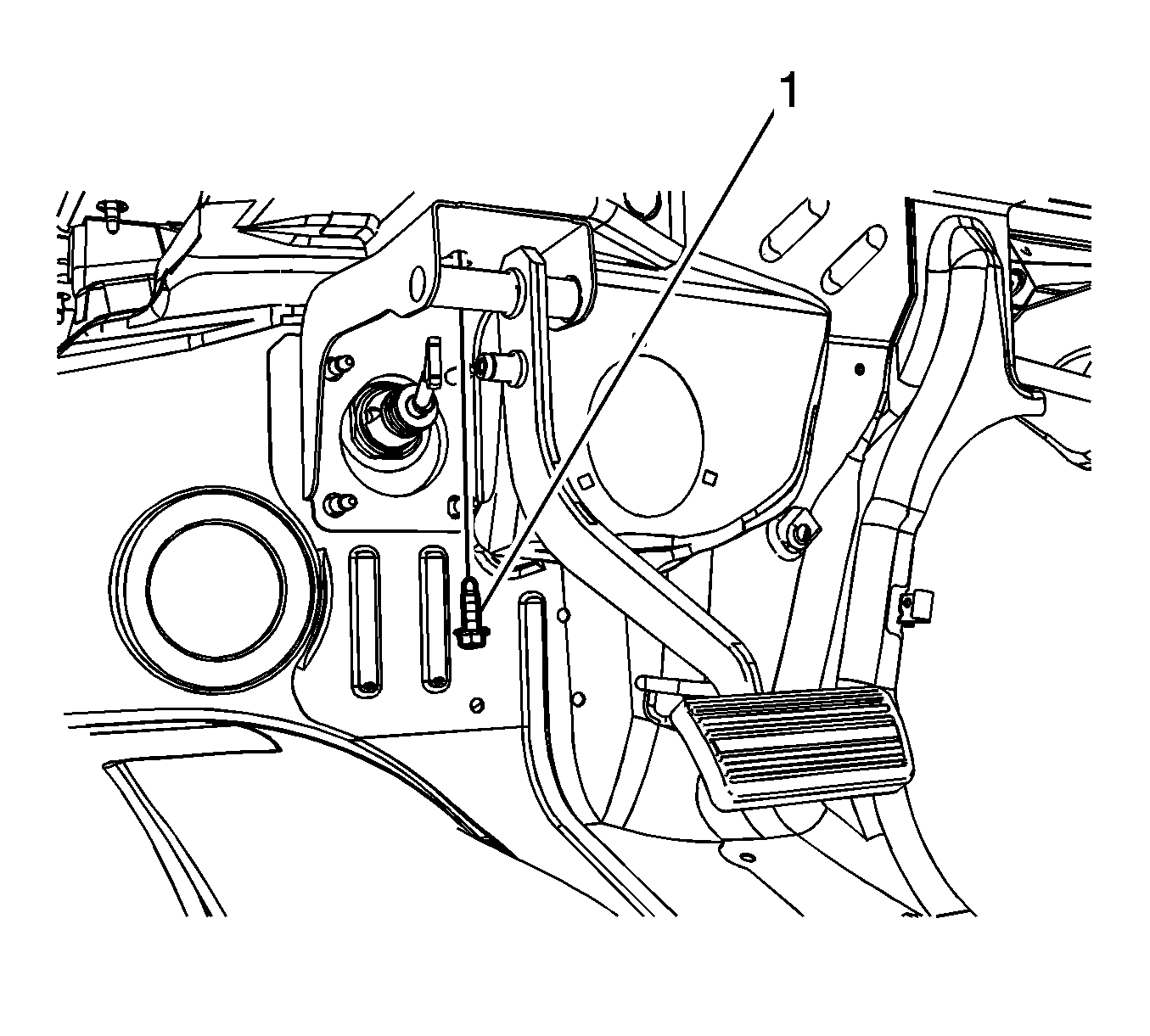
- Remove the power brake booster pushrod retaining clip bolt (1).
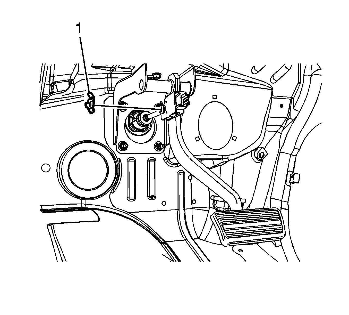
- Remove the power brake booster pushrod retaining clip (1).
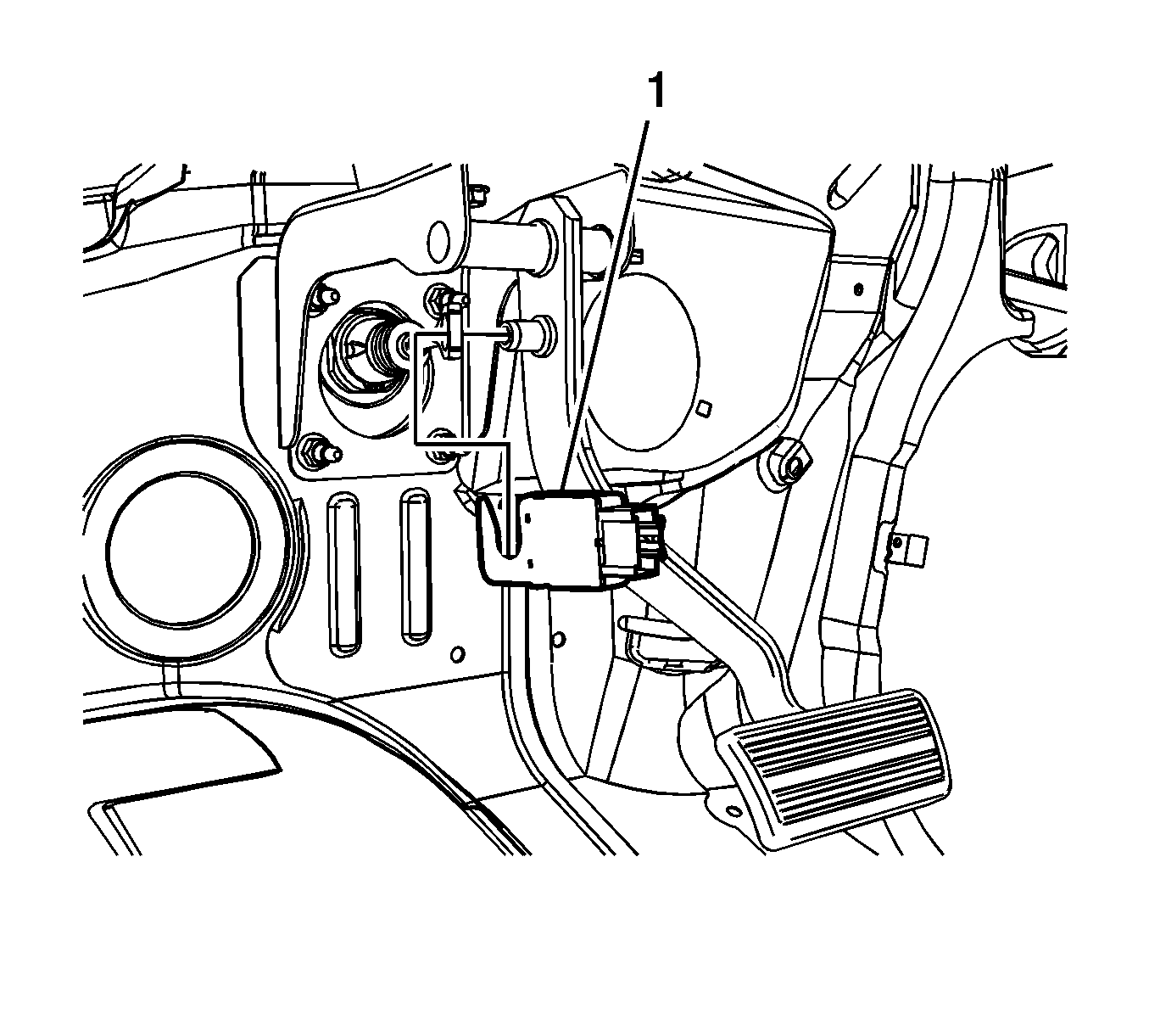
- Disconnect the stoplamp switch electrical connector.
- Disconnect the power brake booster pushrod and remove the stoplamp switch (1).
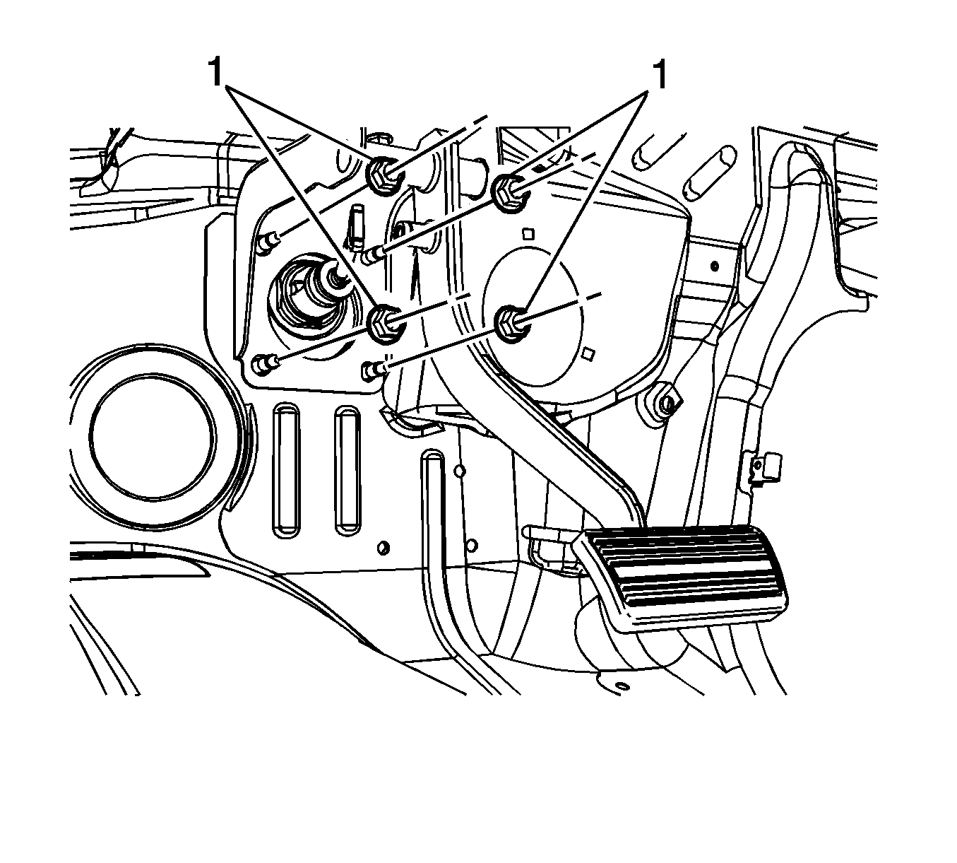
- Remove the power brake booster nuts (1).
- Remove the brake pedal bracket bolt (1).
- Remove the brake pedal assembly.
Installation Procedure
- Install the brake pedal assembly.
- Loosely install the brake pedal bracket bolt (1).
- Install the power brake booster nuts (1) and tighten to 36 N·m (27 lb ft).
- Tighten the brake pedal bracket bolt to 33 N·m (24 lb ft).
- Apply a thin coat of high temperature lubricant, GM P/N 12345994 (Canadian P/N 10953501) to the brake pedal pivot pin.
- Install the stoplamp switch (1) and simultaneously connect the power brake booster pushrod.
- Connect the stoplamp switch electrical connector.
- Install the power brake booster pushrod retaining clip (1).
- Rotate the power brake booster retaining clip 360 degrees to ensure the clip is fully engaged in the brake pedal pivot pin groove.
- Install the power brake booster pushrod retaining clip bolt (1) and tighten to 10 N·m (89 lb in).

Caution: Refer to Fastener Caution in the Preface section.


