Caution: Refer to Fastener Caution in the Preface section.
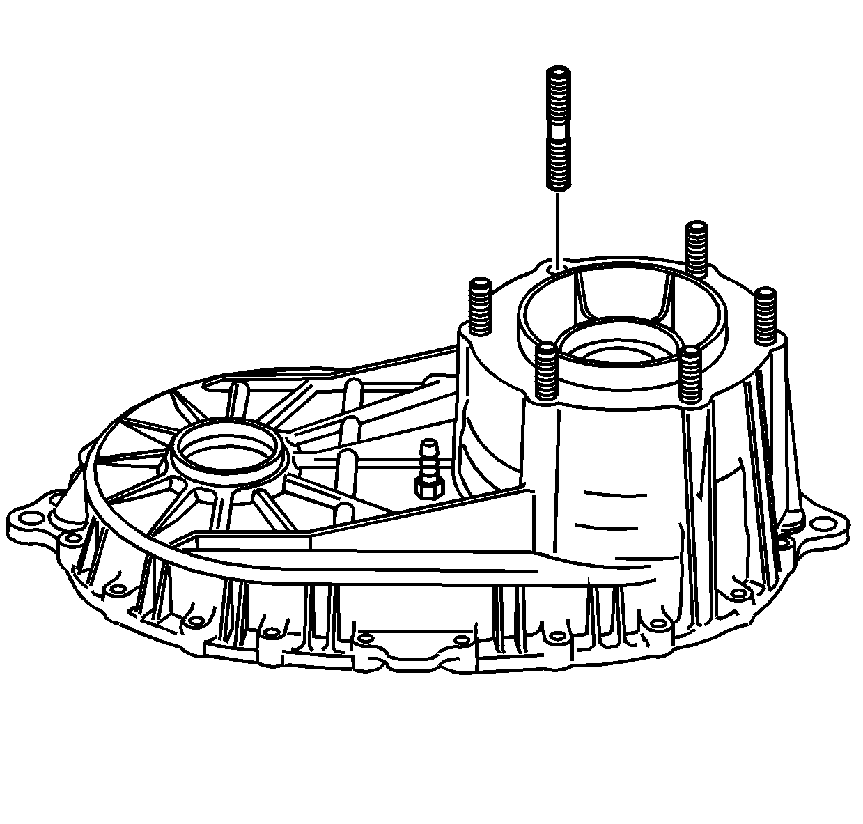
- If removed, install the transfer case mounting studs and tighten the mounting studs to
10 N·m (89 lb in).
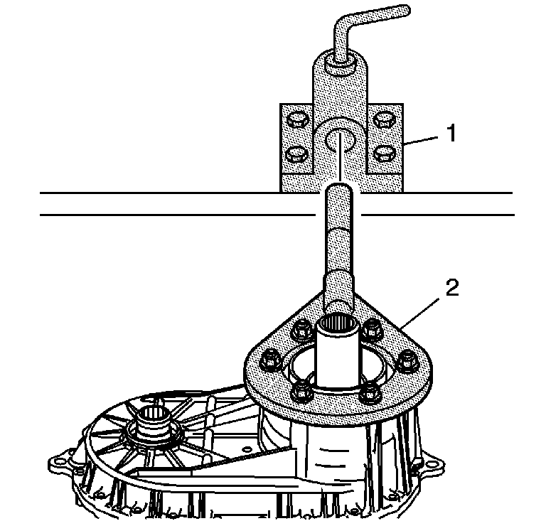
- Attach the
J 45759 assembly fixture
(2) to the front case half using the adapter studs. All of the assembly procedures can be performed with the case mounted to the
J 45759 assembly fixture
(2).
- Install the
J 45759 assembly fixture
(2) into the
J 3289-20 holding fixture
(1)
and secure with pivot pin.
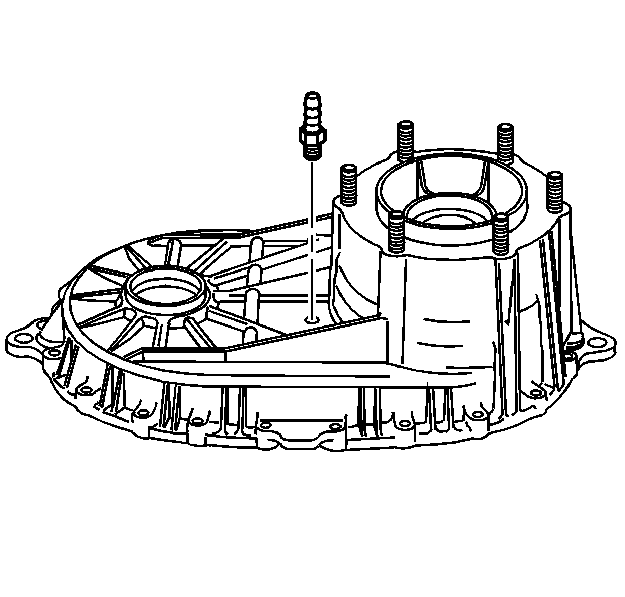
- If removed, apply pipe sealant GM P/N 12346004 (Canadian P/N 10953480)
to the threads on the vent.
- Install the vent and tighten to
6 N·m (53 lb in).
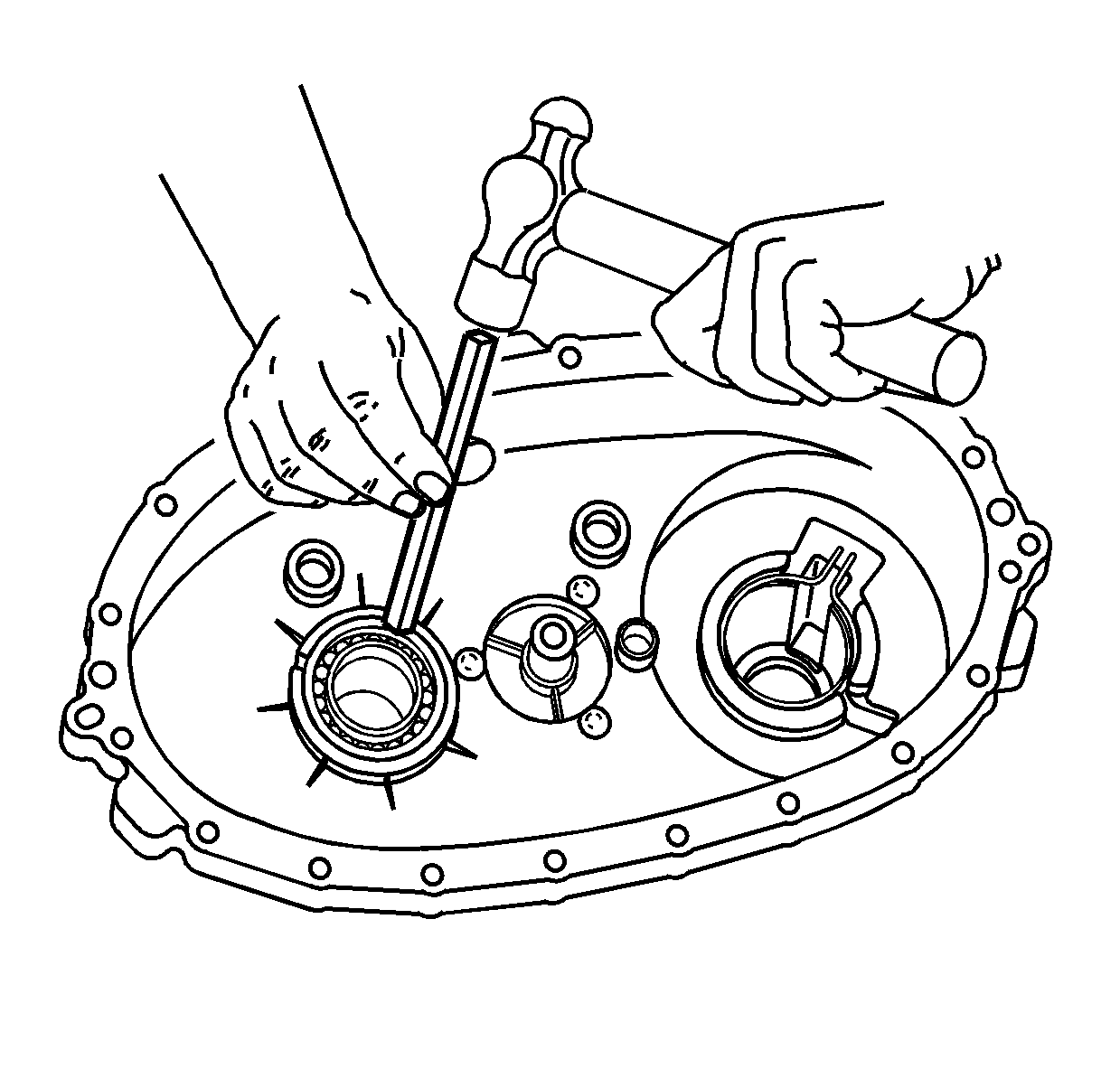
- Install the front output shaft rear
bearing in the rear case half.
| • | Use a hammer and a brass drift only on the outer bearing race. |
| • | Ensure the bearing is kept square to the bore while installing. |
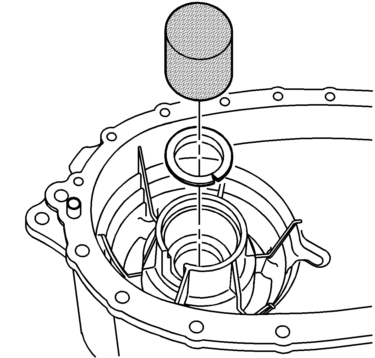
Note: Lubricate all bearings and bearing journals with transfer case fluid during installation.
- Install the input shaft bushing in the front case half using the
J 36373 bearing installer
and a hammer.
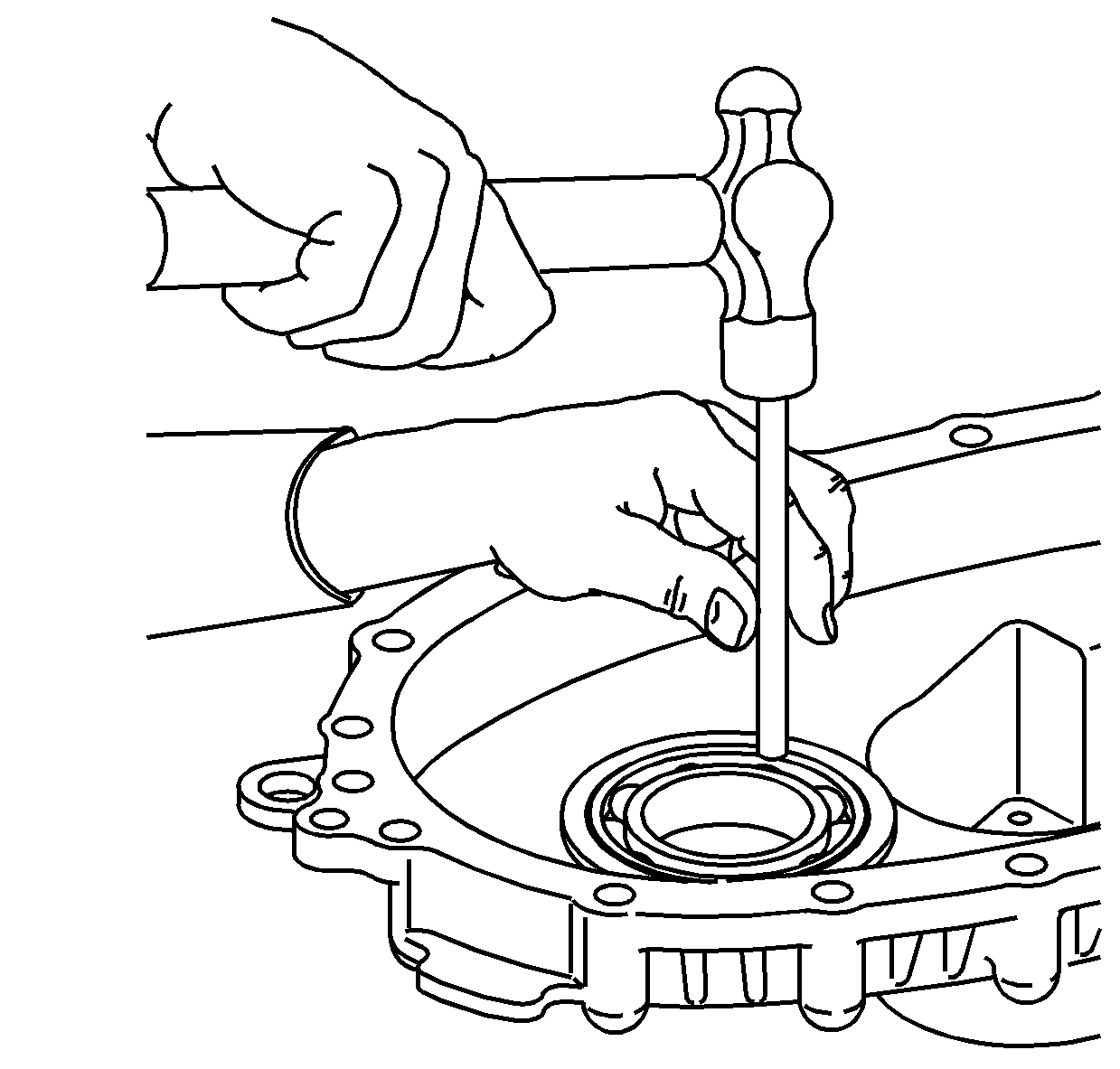
- Install the front bearing for the front
output shaft in the front case half.
| • | Use a hammer and a brass drift only on the outer bearing race. |
| • | Ensure the bearing is kept square to the bore while installing. |
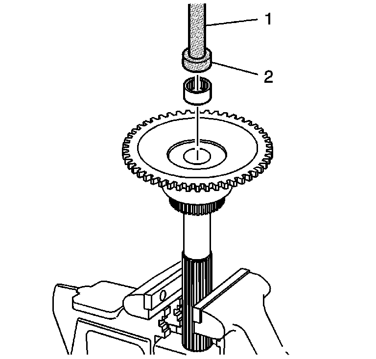
- If removed, install the input shaft
rear support bearing in the rear output shaft using
J 42176 driver handle
(1) and
J 45848 bearing installer
(2).
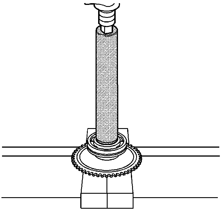
- Using the
J 22828 race installer
and a hydraulic press, install the rear output shaft bearing with the retaining ring groove towards the gear.
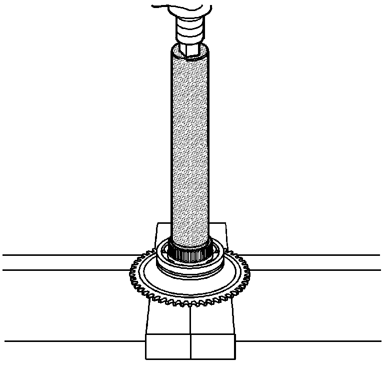
- Using the
J 22828 race installer
and a hydraulic press, install a NEW speed reluctor wheel.
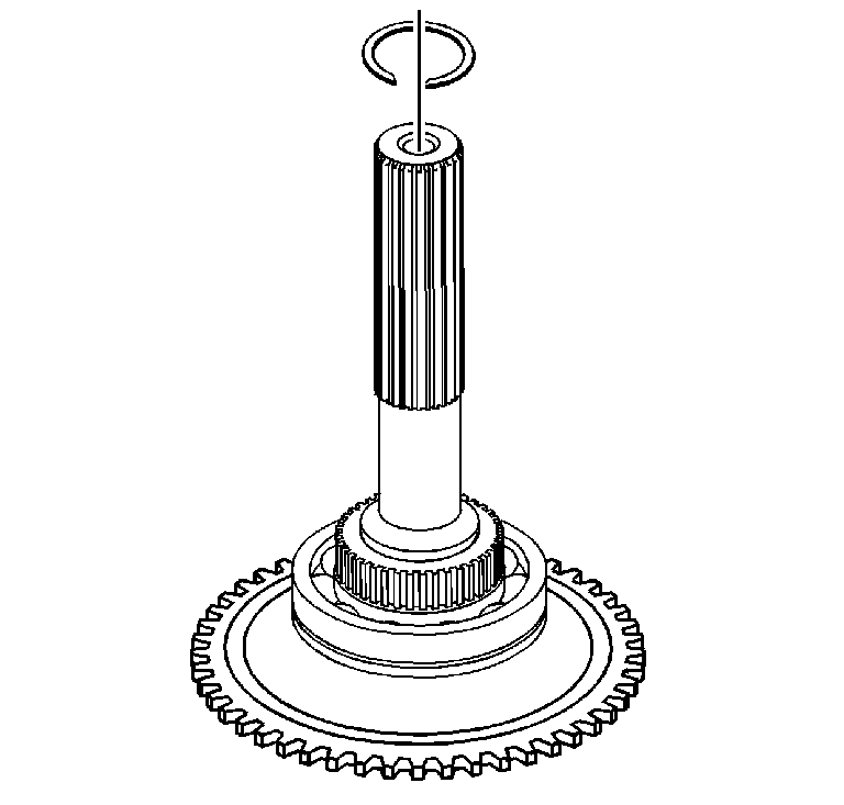
- Install a NEW retaining ring for the
rear output shaft bearing.
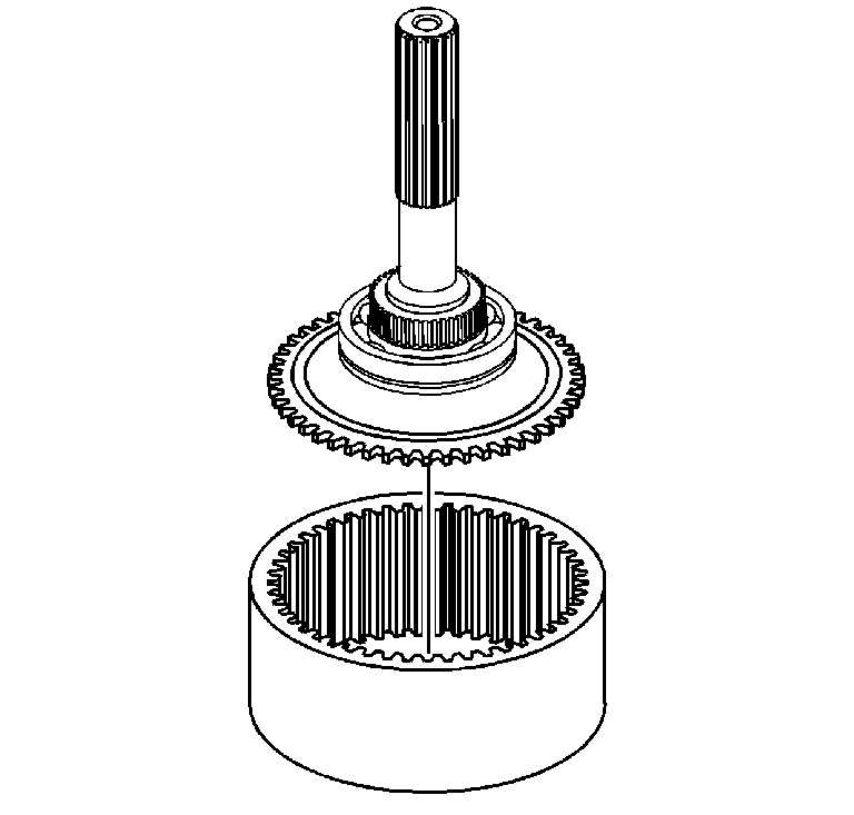
- Install the rear output shaft in the annulus gear.
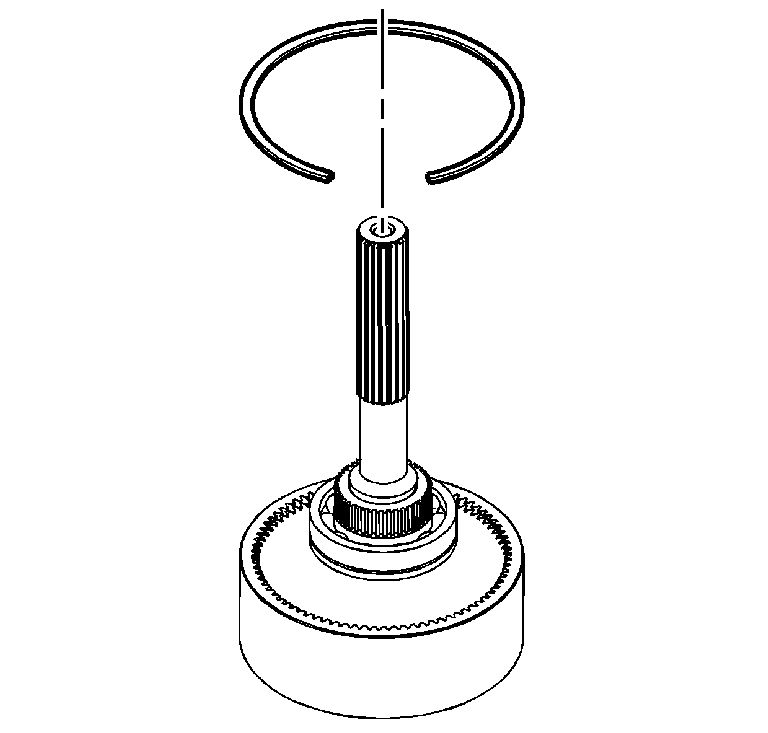
Warning: The vehicle could roll while in park if the annulus gear becomes disengaged from the rear output shaft. Always install a new rear output shaft to annulus gear retaining ring. Ensure the rear
output shaft retaining ring is fully seated in the annulus gear.
Caution: Damage may occur to the viscous coupling if the retaining ring for the rear output shaft to the annulus gear fails or becomes dislodged during vehicle operation. Always install a new rear output
shaft to annulus gear retaining ring. Ensure the rear output shaft retaining ring is fully seated in the annulus gear.
- Install a NEW annulus gear retaining ring.
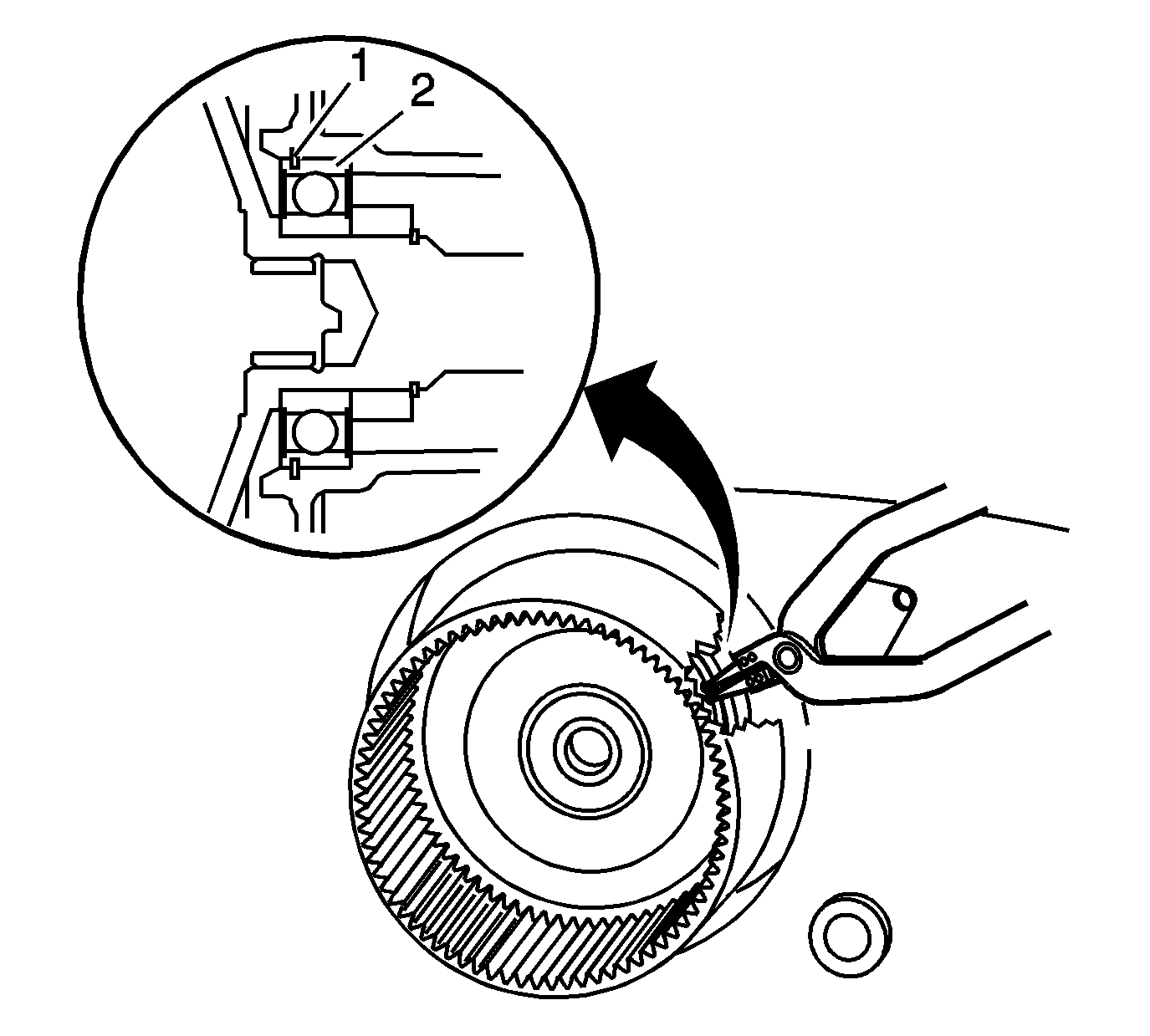
- Install the rear output shaft in the rear case.
| • | Spread the rear output shaft rear bearing outer retaining ring (1). |
| • | Using a soft-face hammer, tap on the rear output shaft. |
- Ensure the retaining ring (1) is installed in the groove of the rear output shaft bearing (2).
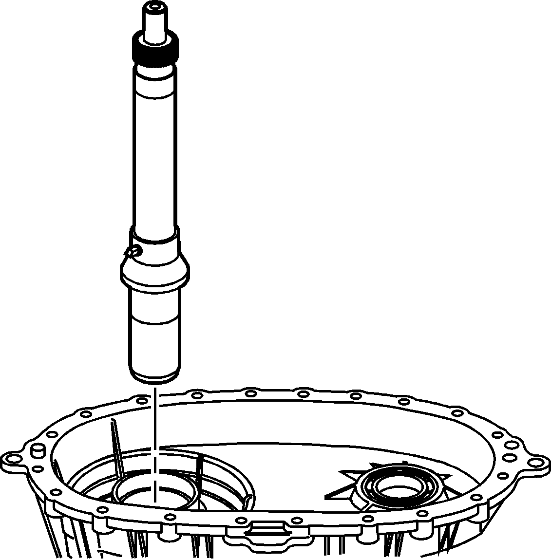
- Install the input shaft in the front case.
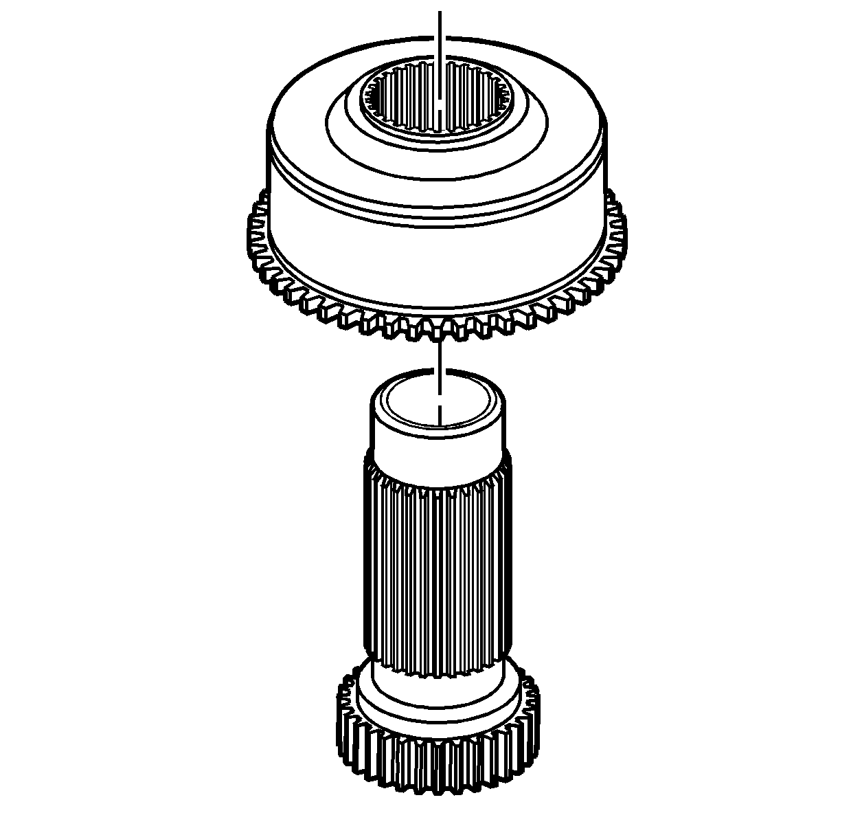
- Install the viscous coupling on the sun gear.
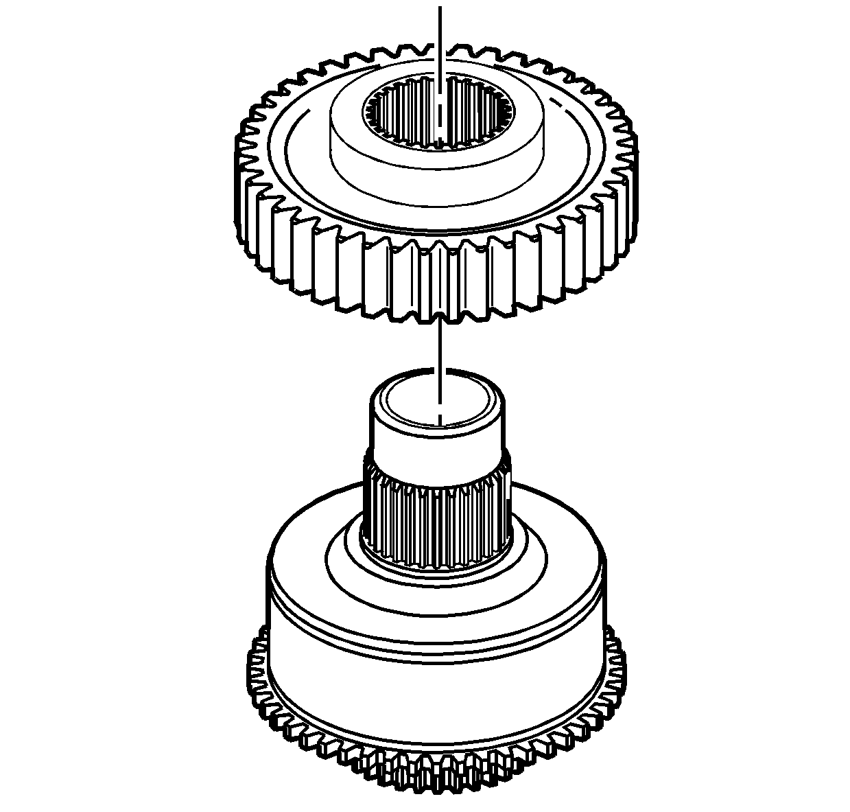
- Install the drive gear on the sun gear.
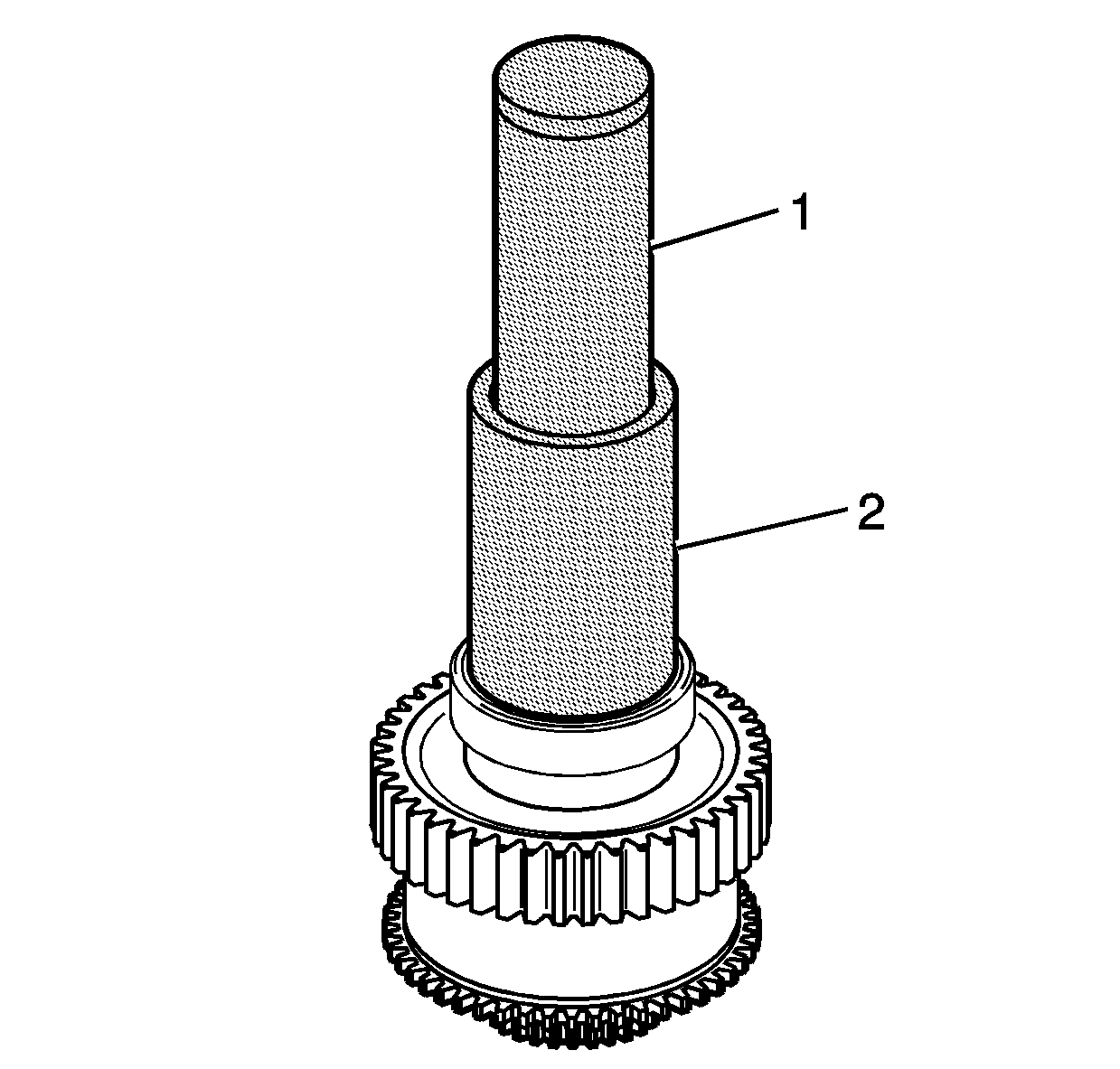
- Using a hammer with the
J 45540 ring/bearing installer
(2) and the
J 5590 driver
(1), install the bearing on the sun gear. Ensure the bearing is fully seated against the drive
gear.
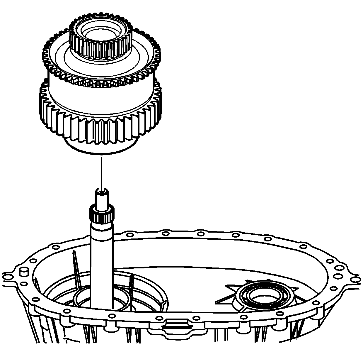
- Install the sun gear, with the drive
gear and the viscous coupling, on the input gear.
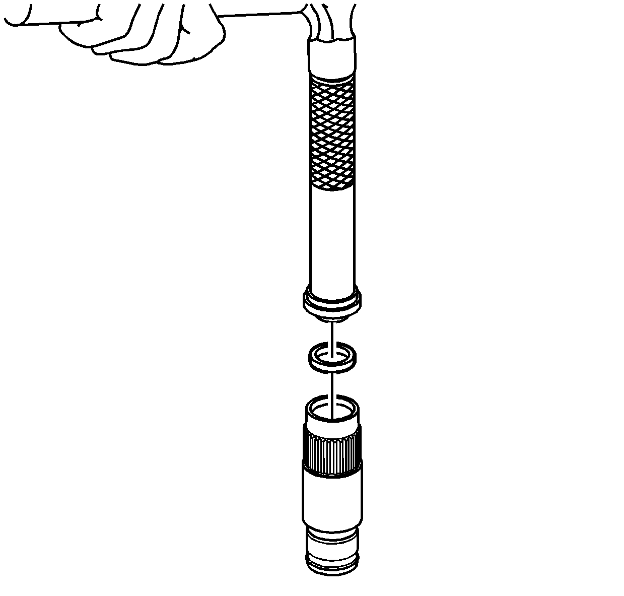
- If it is a new shaft, or if the cup plug was removed,
install the cup plug in the front output shaft using a suitable driver. Install the cup plug 1 mm (0.039 in) from flush with the end of the shaft.

Note: Ensure to align the marks of the drive chain and sprockets, if using the chain and sprockets again.
- Install the drive chain on the drive sprocket.
| • | The blue link on the chain faces up. |
| • | Align the chain, if using it again, with the alignment marks made during disassembly. |
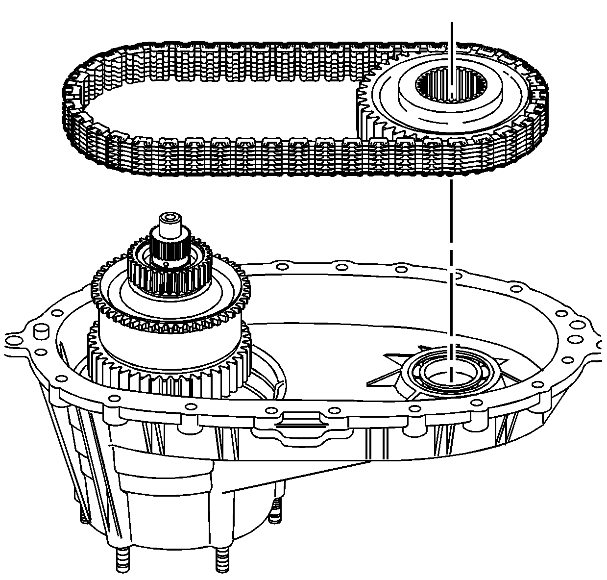
- Install the driven sprocket and the chain.
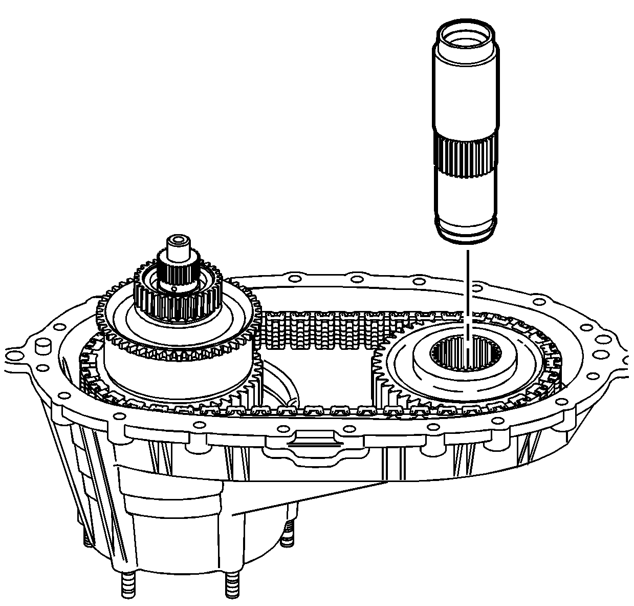
- Install the front output shaft in the driven sprocket and the bearing.
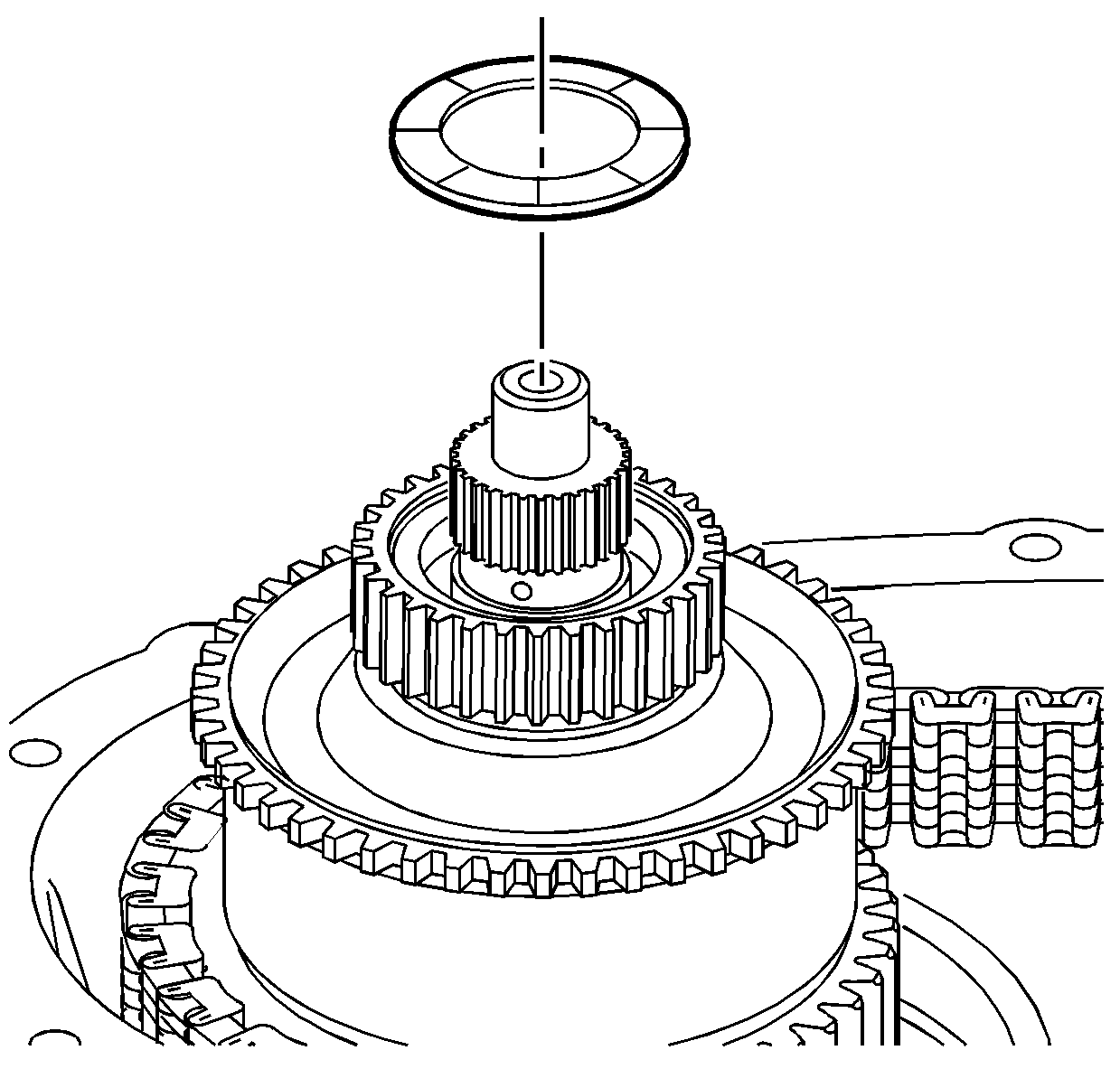
- Lubricate the sun gear thrust washer with
J 36850 lubricant
or equivalent.
- Install the sun gear thrust washer.
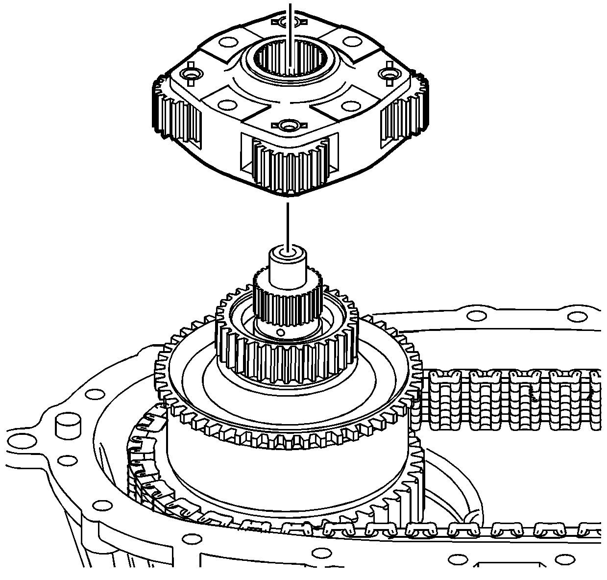
- Install the planetary carrier assembly.
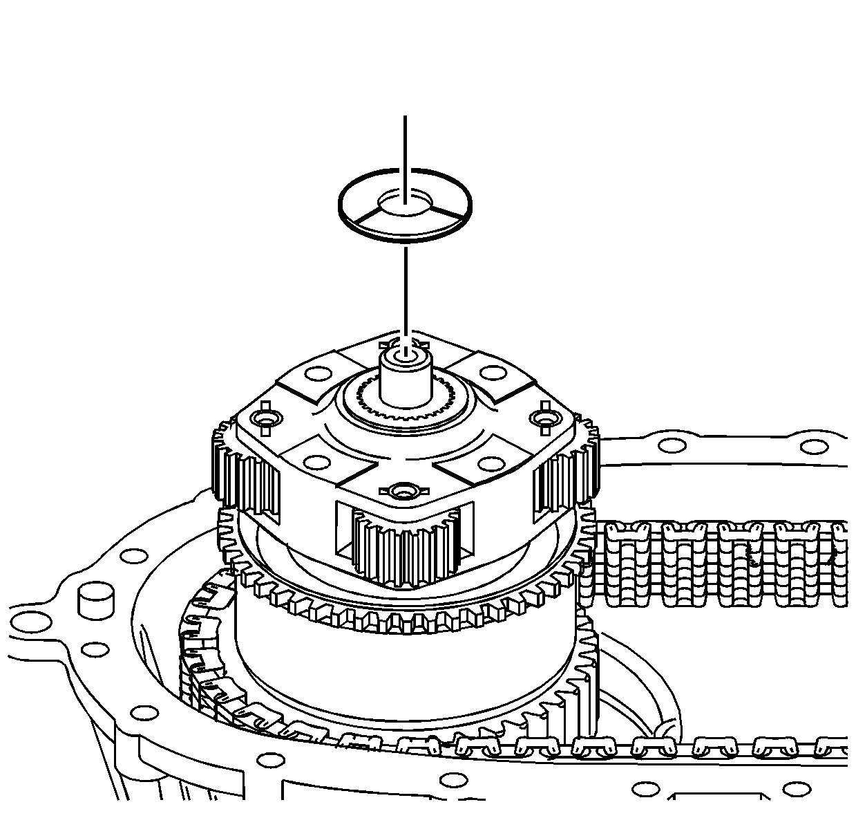
- Lubricate the sun gear thrust washer with
J 36850 lubricant
or equivalent.
- Install the planetary carrier thrust washer.
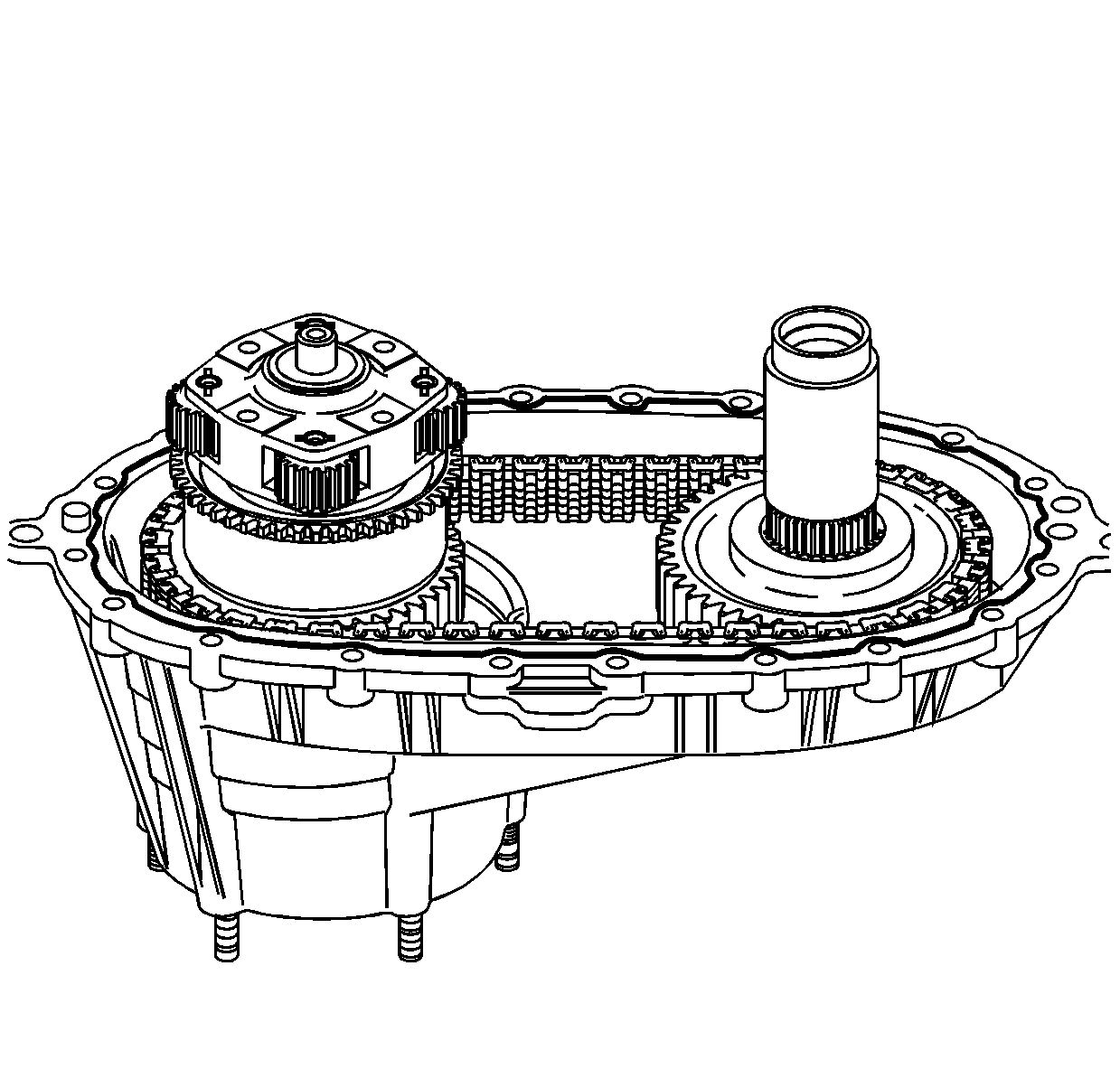
Note:
| • | Ensure that both the sealing surfaces on the front and rear case halves are free of dirt, oil, and cleaning solvent. |
| • | Ensure the locating pins are installed in the front case half. |
- Install the locating pins in the front case, if necessary.
- Apply a 3.175 mm (1/8 in) bead of room temperature vulcanizing (RTV) sealant GM P/N 12345739 (Canadian P/N 10953541) or equivalent to the mating surfaces of the front case half.
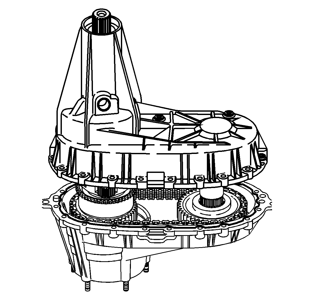
- Lower the rear case half into place.
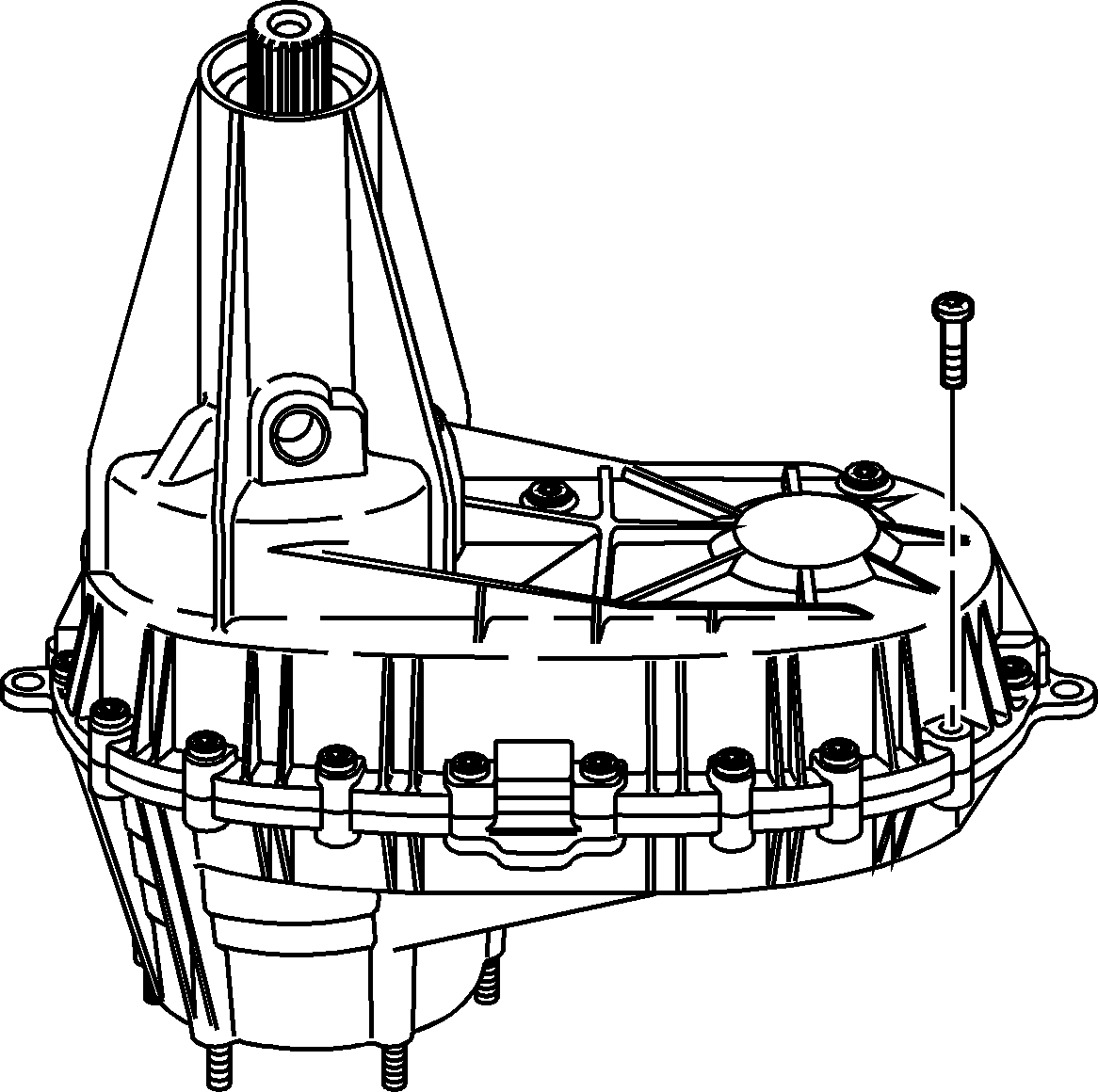
- Install the case bolts, washers, and brackets.
- Tighten the case bolts to
21 N·m (15 lb ft).
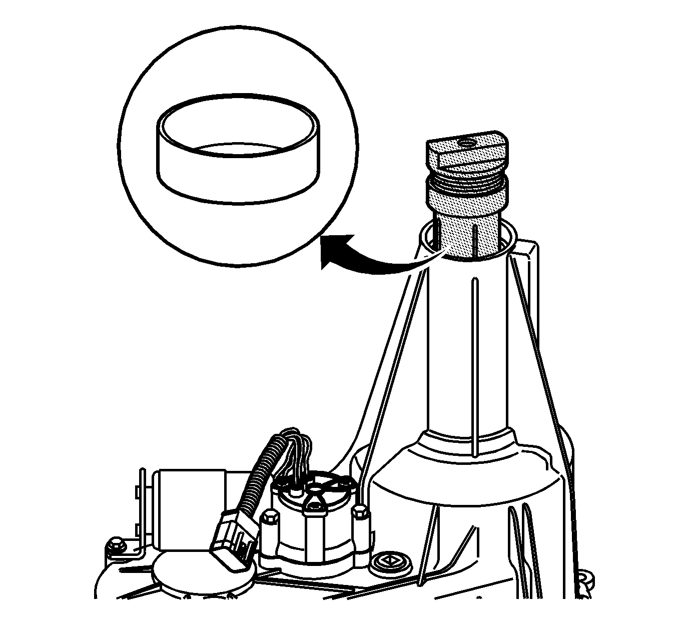
- Using the
J 45380 bushing remover/installer
, install the rear output shaft bushing, if removed or new.
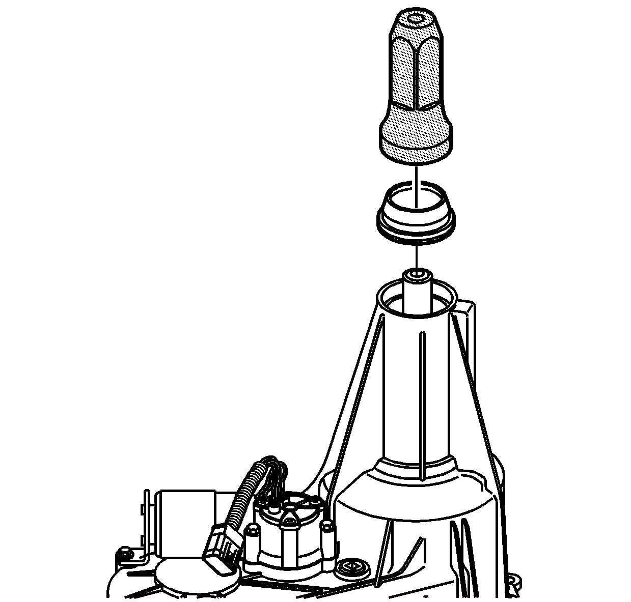
- Using the
J 45756 seal installer
, install the rear output shaft seal.
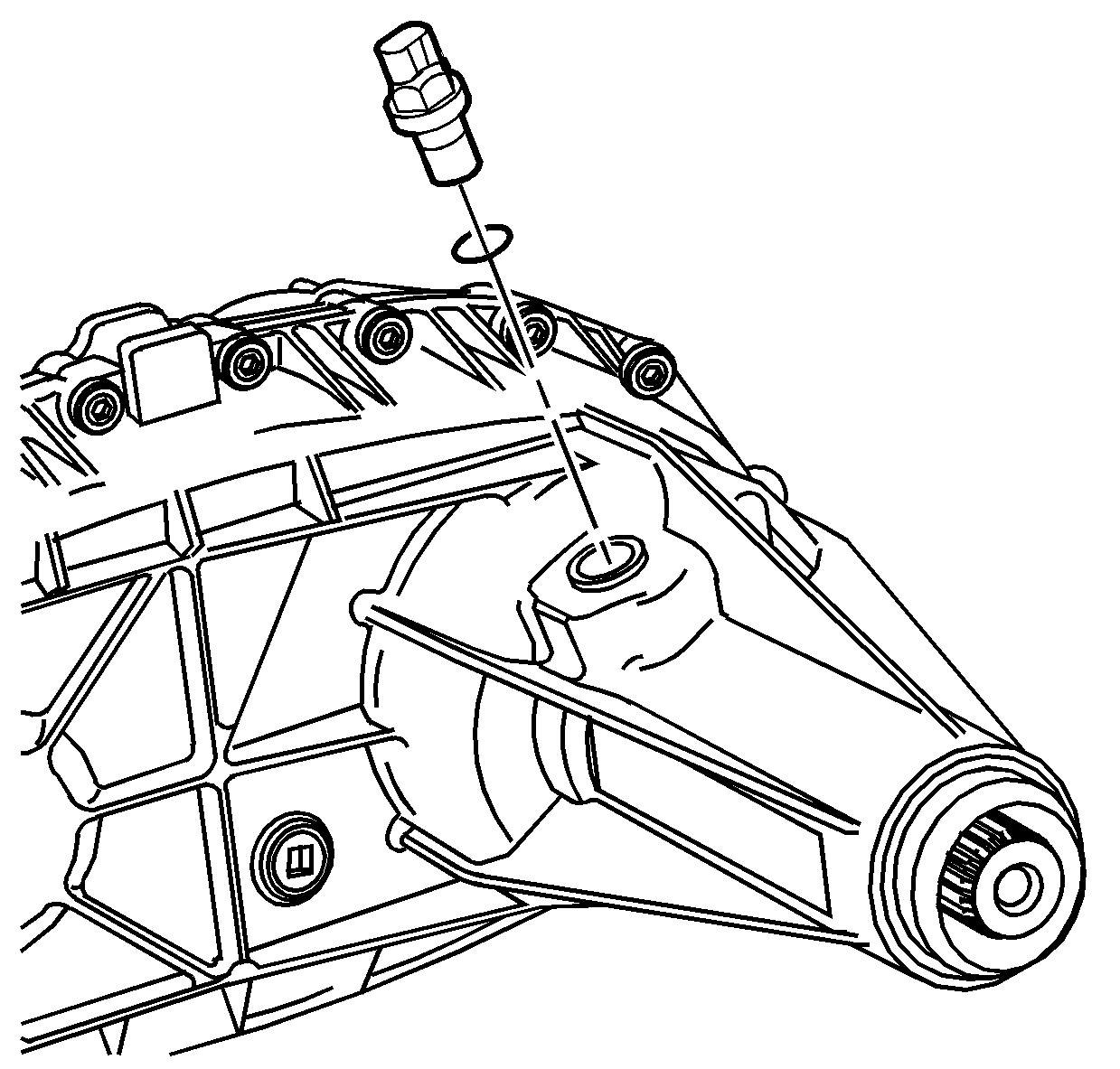
- Install the vehicle speed sensor (VSS) with a NEW O-ring seal.
- Tighten the VSS to
17 N·m (13 lb ft).
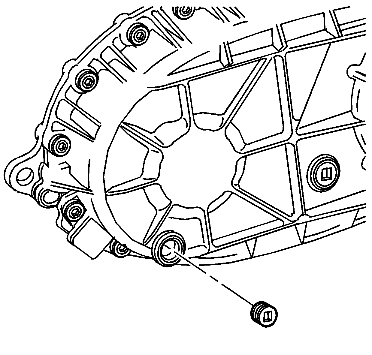
- Apply pipe sealant GM P/N 12346004 (Canadian P/N 10953480) to the threads on the
drain plug and fill plug.
- Install the drain plug and tighten to
25 N·m (18 lb ft).
- Install the fill plug and tighten to
25 N·m (18 lb ft).
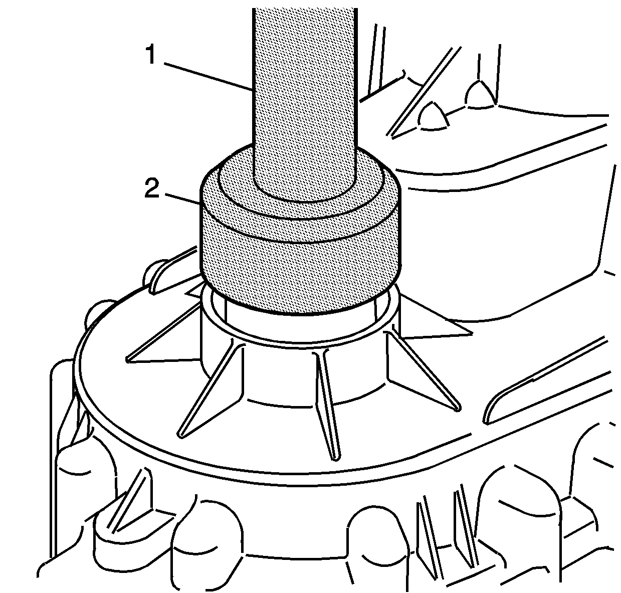
- Using the
J 43484 seal installer
(2) and the
J 8092 driver
(1), install the front output shaft seal.
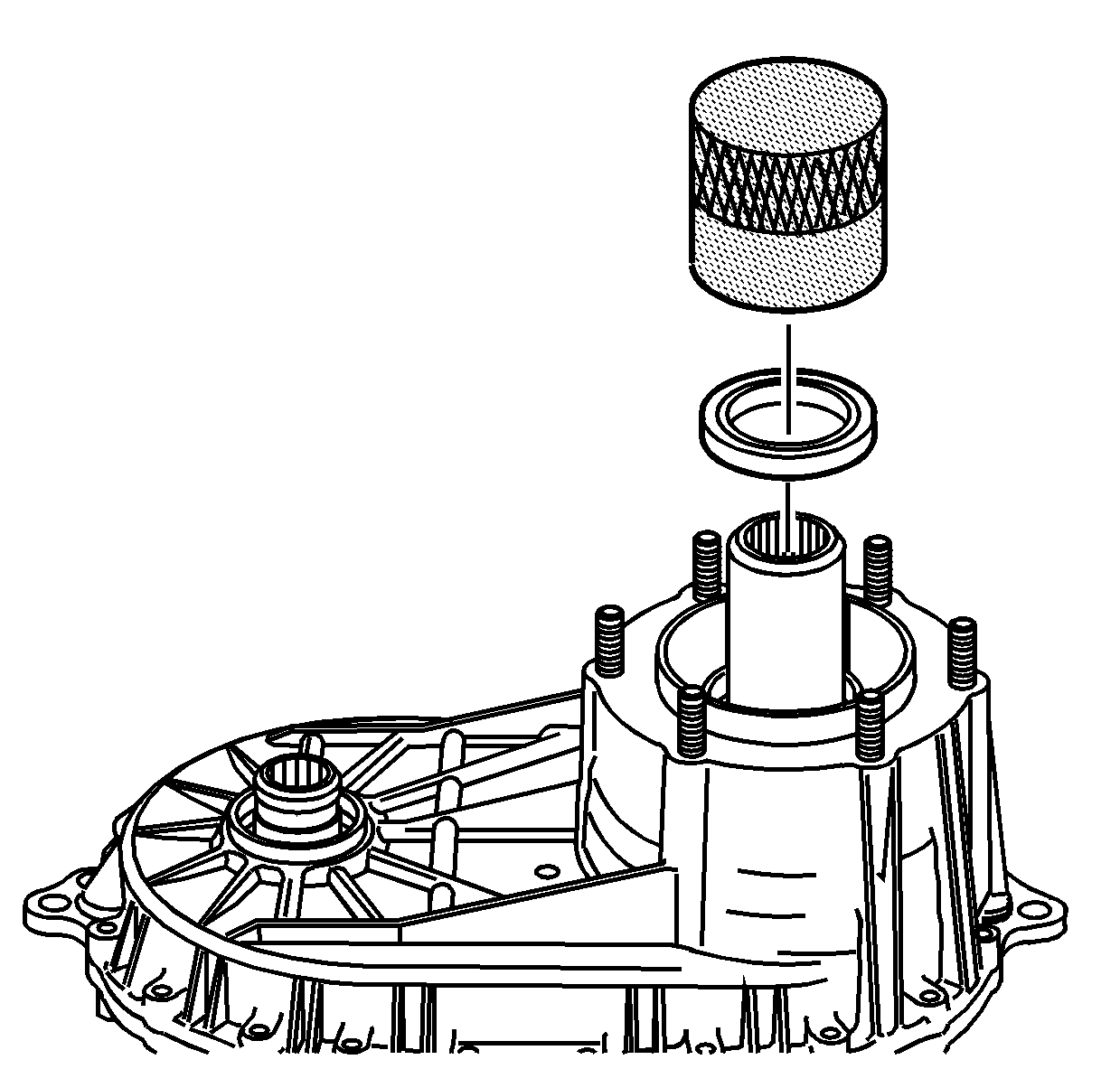
- Using the
J 45758 seal installer
, install the front input shaft seal.
- Remove the transfer case from the
J 45759 assembly fixture
.


