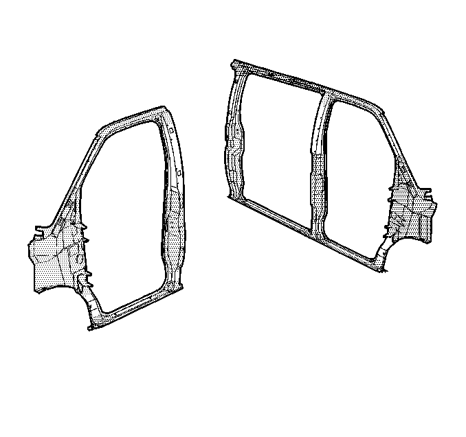
For 1990-2009 cars only
General Sectioning Procedure

Note: Sectioning should take place only in recommended areas. Failure to do so may compromise the structural integrity of the vehicle.
Note: This procedure does not apply to the front hinge pillar. See front hinge pillar sectioning procedures.
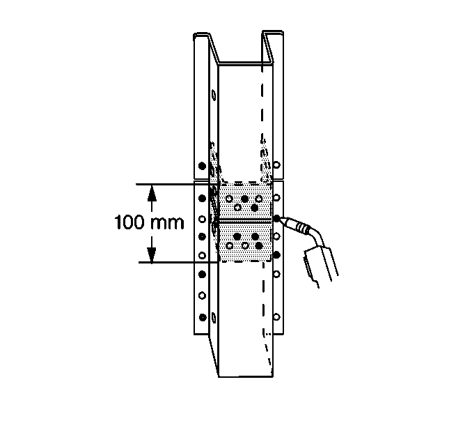
| • | When sectioning the door frame opening in areas where there is no inner reinforcement, a 100 mm (4 in) backing plate must be used behind the joint to ensure a solid and secure weld |
| • | Backing plates can be cut from the unused portion of the door frame opening service part. |
| • | The specific areas to be sectioned are determined by the extent of damage to the vehicle. |
Removal Procedure
- Disable the SIR system. Refer to SIR Disabling and Enabling.
- Disconnect the negative battery cable. Refer to Battery Negative Cable Disconnection and Connection.
- Remove all related panels and components.
- Visually inspect and repair as much of the damage as possible to factory specification.
- Note the location and remove the sealers and anti-corrosion materials from the repair area, as necessary. Refer to Anti-Corrosion Treatment and Repair.
- Measure and compare the service part with the damaged part to choose the areas where sectioning can best be performed.
- Cut the door frame opening where sectioning is to be performed. Do not damage the inner panels or reinforcements.
- Locate, mark, and drill out all factory welds. Note the number and location of welds for installation of the service part.
- Remove the damaged area of the door frame opening.
Warning: Refer to Approved Equipment for Collision Repair Warning in the Preface section.

Warning: Refer to Foam Sound Deadeners Warning in the Preface section.
Note: Do not damage any inner panels or reinforcements.
Installation Procedures
- On the service part, mark a horizontal line to leave a gap of one and one-half times the thickness of the metal at the sectioning joint.
- Cut the outer door frame opening service part along this line.
- Cut a 100 mm (4 in) piece from the unused portion of the service part for a backing plate.
- Remove the flange on each side of the backing plate so that it will fit behind the sectioning joint.
- Drill 8 mm (5/16 in) holes for plug welding in the service part in locations noted from the original panel.
- Drill holes for plug welding along the sectioning cuts on both the service part and the original panel.
- Locate these holes approximately 25 m (1 in) from the edge of the sectioning cuts.
- Prepare mating surfaces and position the backing plates with 50 mm (2 in) of the backing plate exposed, and plug weld.
- Apply GM-approved weld-thru coating or equivalent to all mating surfaces. Refer to Anti-Corrosion Treatment and Repair.
- Position the service part to overlap the exposed 50 mm (2 in) of the backing plate.
- Use three-dimensional measuring equipment to inspect the fit. Refer to Dimensions - Body.
- Plug weld accordingly.
- Stitch weld along the sectioning joint.
- Make 25 mm (1 in) welds along the seam with 25 mm (1 in) gaps between.
- Go back and complete the stitch weld. This will create a solid joint with minimal heat distortion.
- Use frequent measurements to ensure accurate fit and alignment to adjacent panels.
- Clean and prepare welded surfaces.
- Apply the sealers and anti-corrosion materials to the repair area, as necessary. Refer to Anti-Corrosion Treatment and Repair.
- Paint and repair the area. Refer to Basecoat/Clearcoat Paint Systems.
- Install all related panels and components.
- Connect the negative battery cable. Refer to Battery Negative Cable Disconnection and Connection.
- Enable the SIR system. Refer to SIR Disabling and Enabling.

