GM Service Manual Online
For 1990-2009 cars only
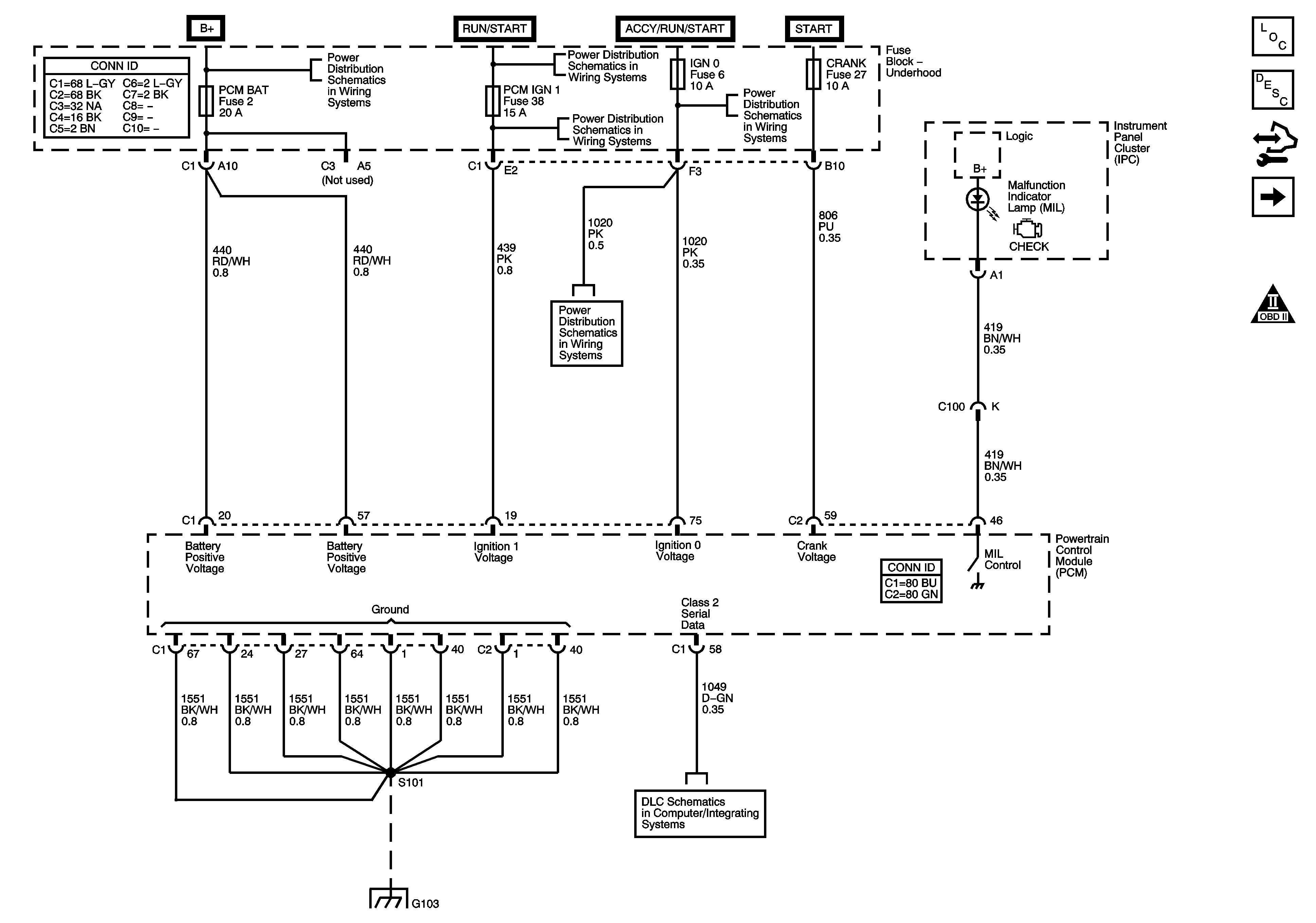
Figure 1:

Module Power, Ground, Serial Data and MIL

Object Number: 1396648  Size: FS
Master Electrical Component List
Powertrain Control Module Description
Control Module References
Engine Data Sensors - 5 Volt and Low Reference
OBD II Symbol Description Notice
B+ Bus - Underhood Fuse Block
Ignition Switch - ACCY/RUN, RUN/START Bus Bars and IGN B Fuse
BTSI, BTSI/BU, O2A, O2B, PCM IGN 1, SPARE and TRLR BU Fuses
BRKS, CRANK, FR WPR, HVAC, IGN 0 and TBC ACC Fuses
G103, G104, G105, G106, G300 and G301
Data Link Connector (DLC) Schematics
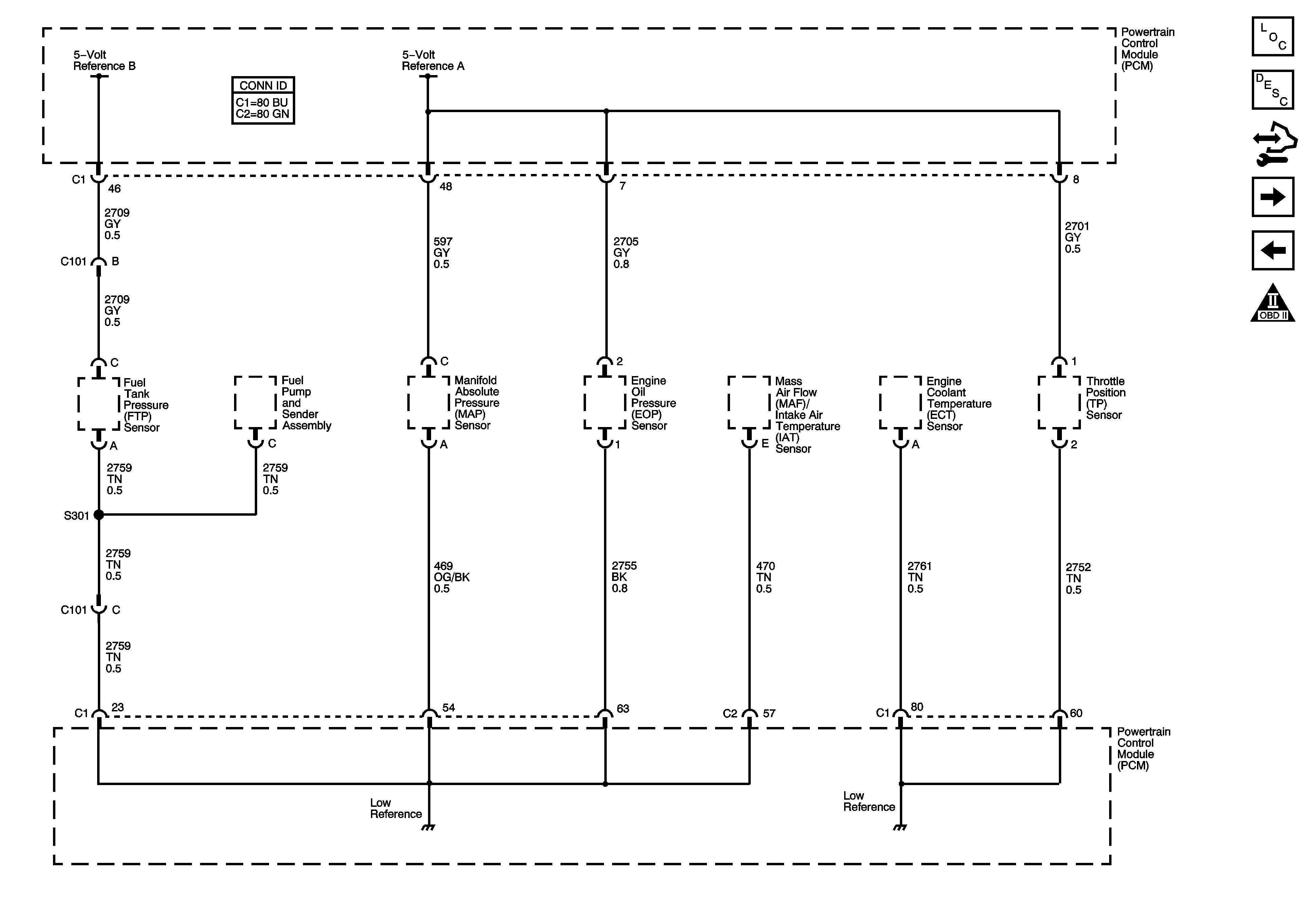
Figure 2:

Engine Data Sensors - 5-Volt and Low Reference

Object Number: 1396651  Size: FS
Master Electrical Component List
Powertrain Control Module Description
Control Module References
Engine Data Sensors - Pressure, Temperature and Position
Module Power, Ground, Serial Data and MIL
OBD II Symbol Description Notice
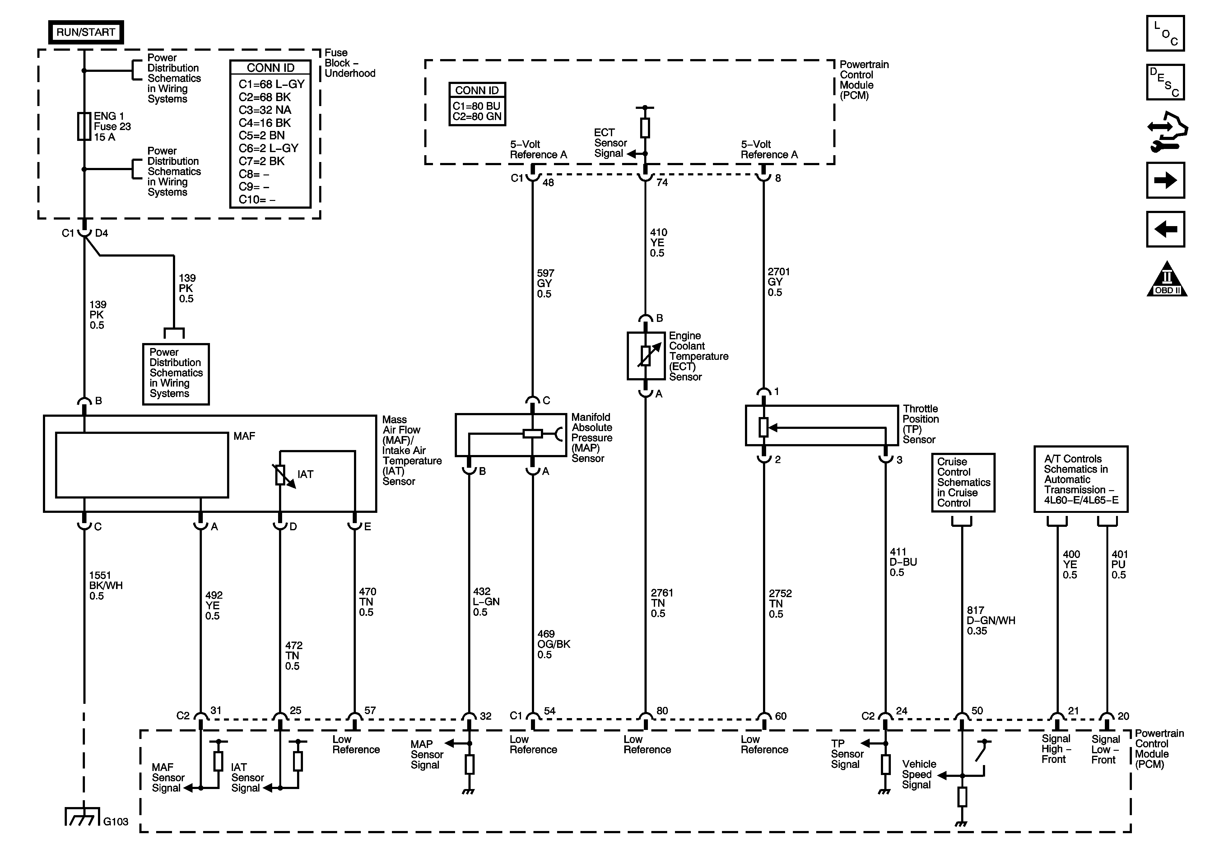
Figure 3:

Engine Data Sensors - Pressure, Temperature and Position


Object Number: 1396654  Size: FS
Master Electrical Component List
Powertrain Control Module Description
Control Module References
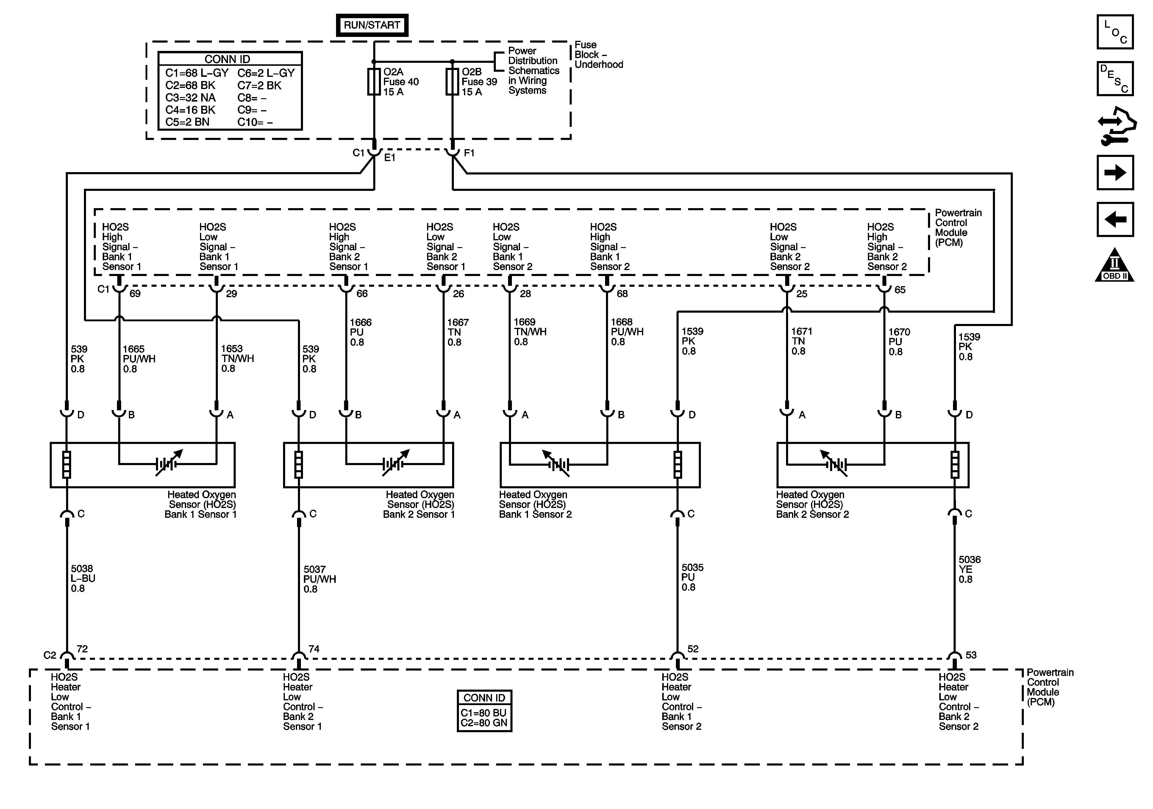
Engine Data Sensors - Oxygen Sensors
Engine Data Sensors - 5 Volt and Low Reference
OBD II Symbol Description Notice
Ignition Switch - ACCY/RUN, RUN/START Bus Bars and IGN B Fuse
ENG 1 and ENG 2 Fuses - 4.3L
w/o JL4
Pressure Controls, Temperature and VSS
G103, G104, G105, G106, G300 and G301
Figure 4:

Engine Data Sensors - Oxygen Sensors


Object Number: 1396657  Size: FS
Master Electrical Component List
Powertrain Control Module Description
Control Module References
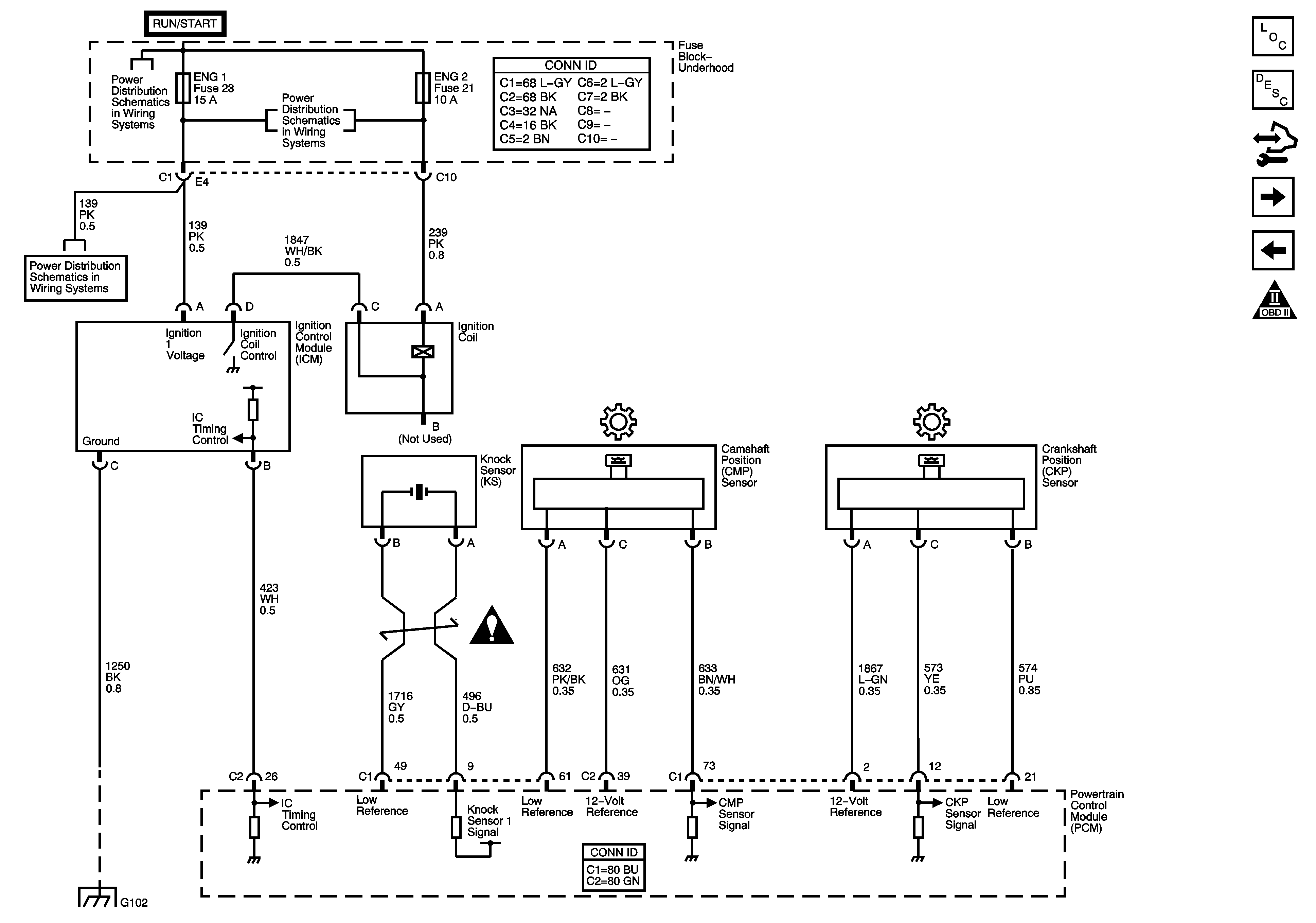
Ignition Controls
Engine Data Sensors - Pressure, Temperature and Position
OBD II Symbol Description Notice
Ignition Switch - ACCY/RUN, RUN/START Bus Bars and IGN B Fuse
Figure 5:

Ignition Controls


Object Number: 1396659  Size: FS
Master Electrical Component List
Powertrain Control Module Description
Control Module References
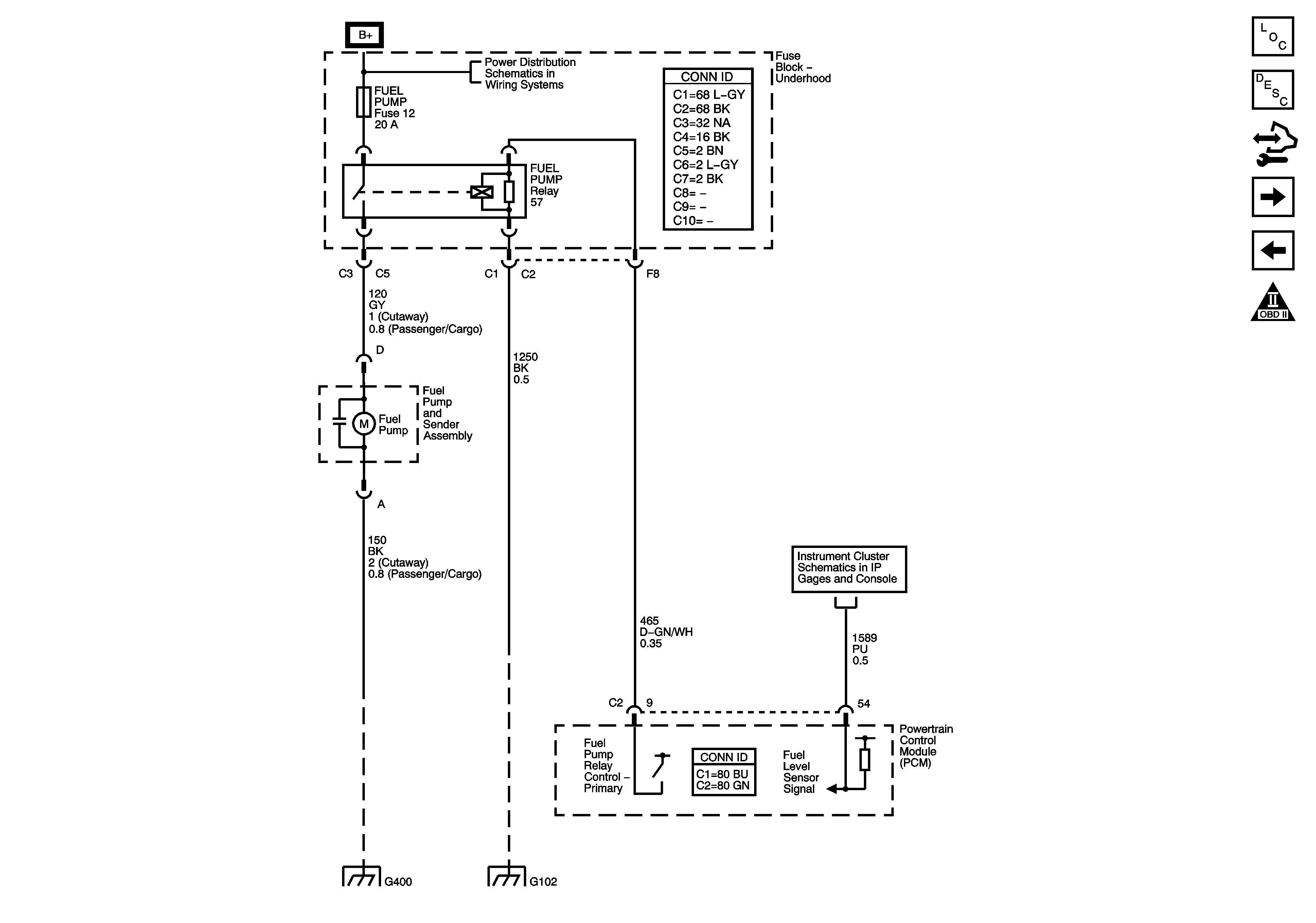
Fuel Controls - Fuel Pump Controls
Engine Data Sensors - Oxygen Sensors
OBD II Symbol Description Notice
Ignition Switch - ACCY/RUN, RUN/START Bus Bars and IGN B Fuse
ENG 1 and ENG 2 Fuses - 4.3L
Engine Controls Schematic Icons
G102
Figure 6:

Fuel Controls - Fuel Pump Controls


Object Number: 1396661  Size: FS
Master Electrical Component List
Powertrain Control Module Description
Control Module References
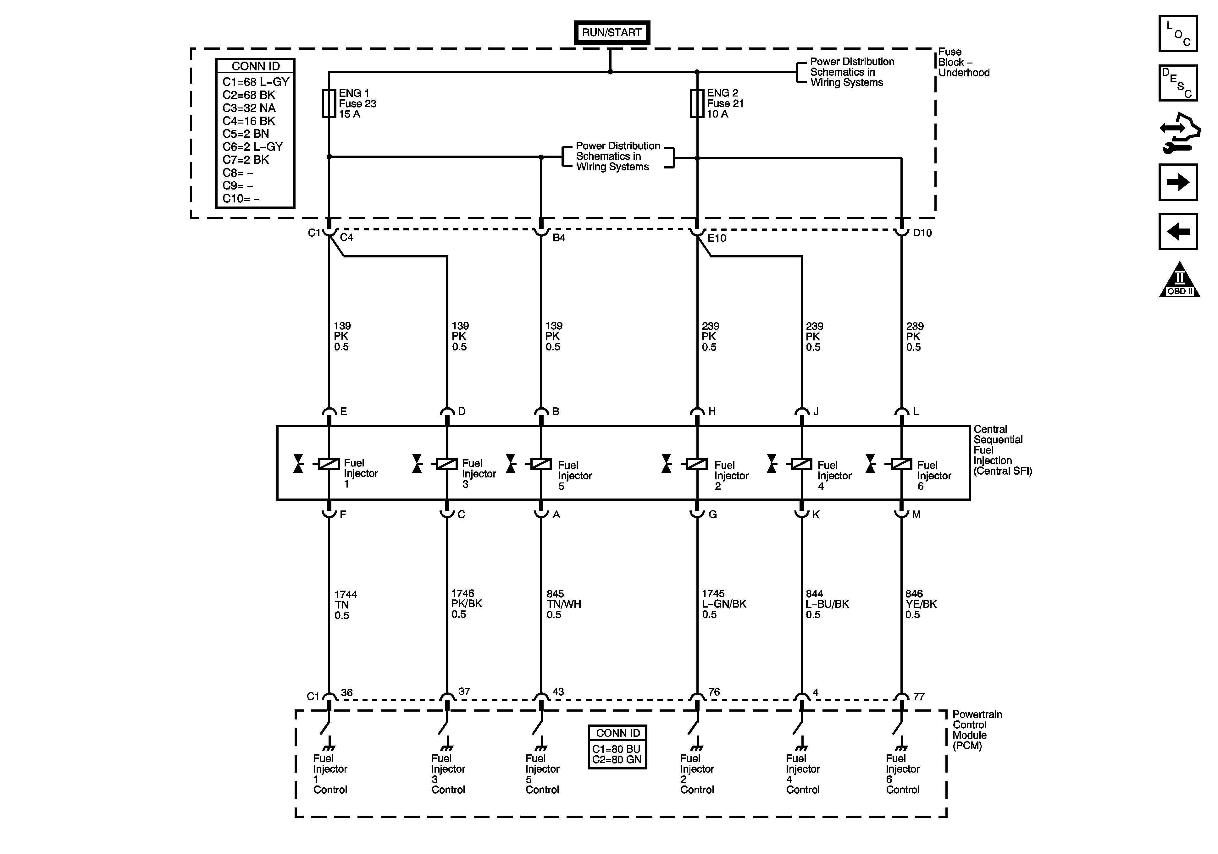
Fuel Controls - Fuel Injectors
Ignition Controls
OBD II Symbol Description Notice
B+ Bus - Underhood Fuse Block
Gages
G400
G102
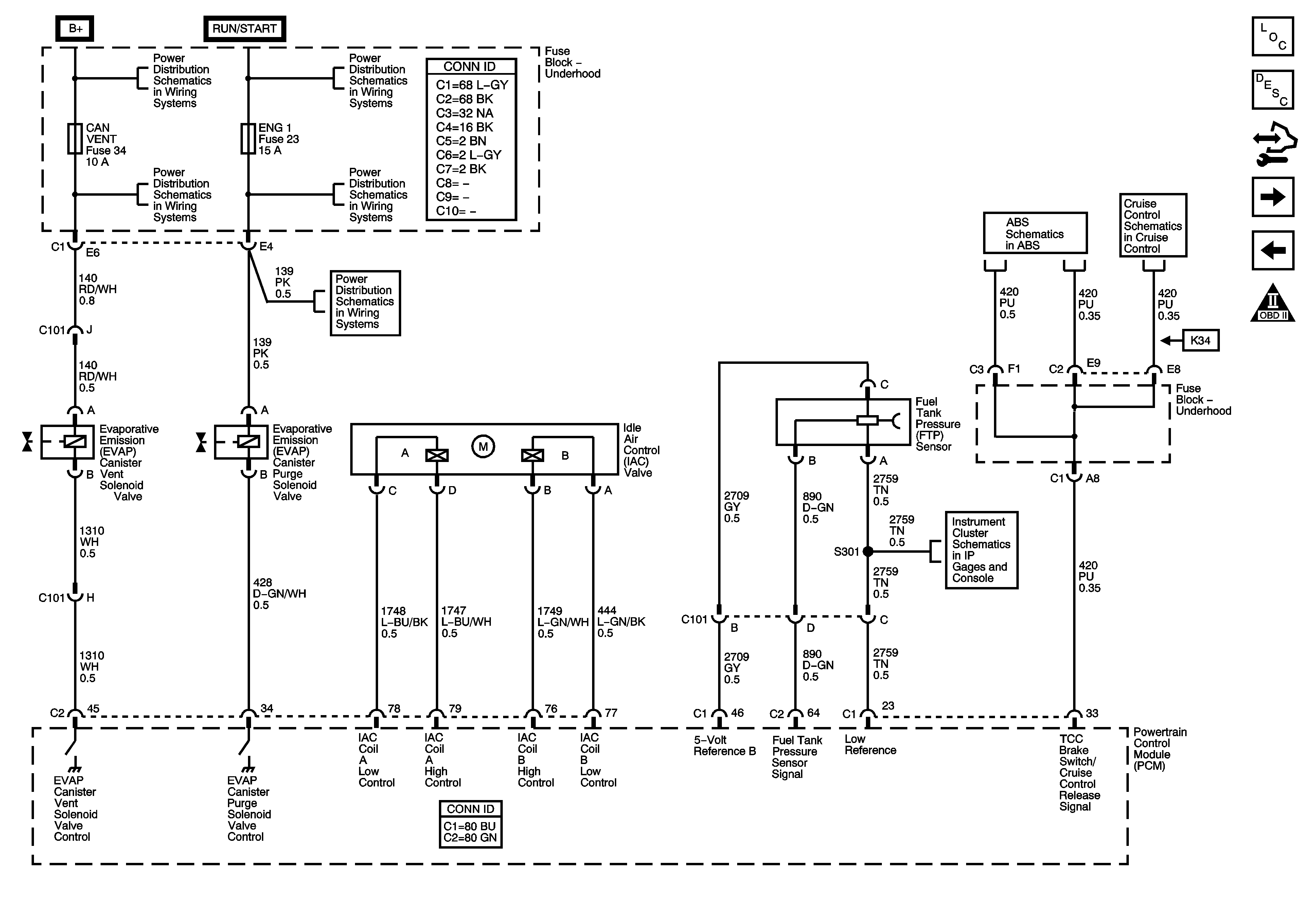
Figure 7:

Fuel Controls - Fuel Injectors


Object Number: 1396664  Size: FS
Master Electrical Component List
Powertrain Control Module Description
Control Module References
Fuel Controls - EVAP and Device Controls
Fuel Controls - Fuel Pump Controls
OBD II Symbol Description Notice
Ignition Switch - ACCY/RUN, RUN/START Bus Bars and IGN B Fuse
ENG 1 and ENG 2 Fuses - 4.3L
Figure 8:

Fuel Controls - EVAP and Device Controls


Object Number: 1396668  Size: FS
Master Electrical Component List
Powertrain Control Module Description
Control Module References
Controlled/Monitored Subsystem and Transmission References
Fuel Controls - Fuel Injectors
OBD II Symbol Description Notice
B+ Bus - Underhood Fuse Block
Ignition Switch - ACCY/RUN, RUN/START Bus Bars and IGN B Fuse
ABS, AUX PWR, BLOW, CAN VENT, CIGAR, IPC, PCM BAT, STOP LP and TRLR Fuses
ENG 1 and ENG 2 Fuses - 4.3L
Gages
Power, Ground, Serial Data, Indicator and Stop lamp Switch - w/o JL4
w/o JL4
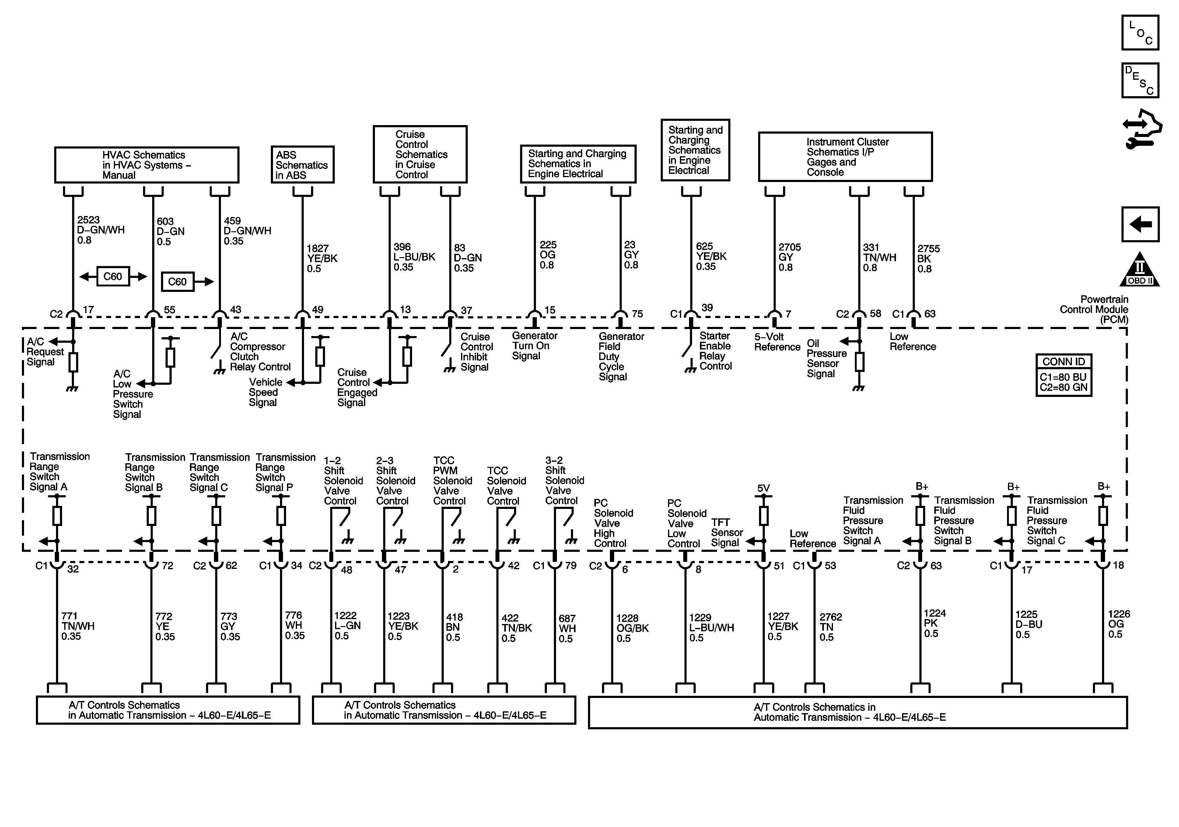
Figure 9:

Controlled/Monitored Subsystem and Transmission References


Object Number: 1396670  Size: FS
Master Electrical Component List
Powertrain Control Module Description
Control Module References
Fuel Controls - EVAP and Device Controls
OBD II Symbol Description Notice
Compressor Controls (C60)
Wheel Speed Sensors and VSS - w/o JL4
w/o JL4
Charging System
Starting System
Gages
PNP Switch, Serial Data and Indicator
Shift Controls and Stop Lamp Switch
Pressure Controls, Temperature and VSS