Turbocharger Coolant Hoses/Pipes Replacement Inlet - LLY, LBZ
Removal Procedure
- Remove the air cleaner outlet duct. Refer to Air Cleaner Outlet Duct Replacement.
- Remove the engine cover. Refer to Engine Cover Replacement.
- Drain the cooling system. Refer to Cooling System Draining and Filling.
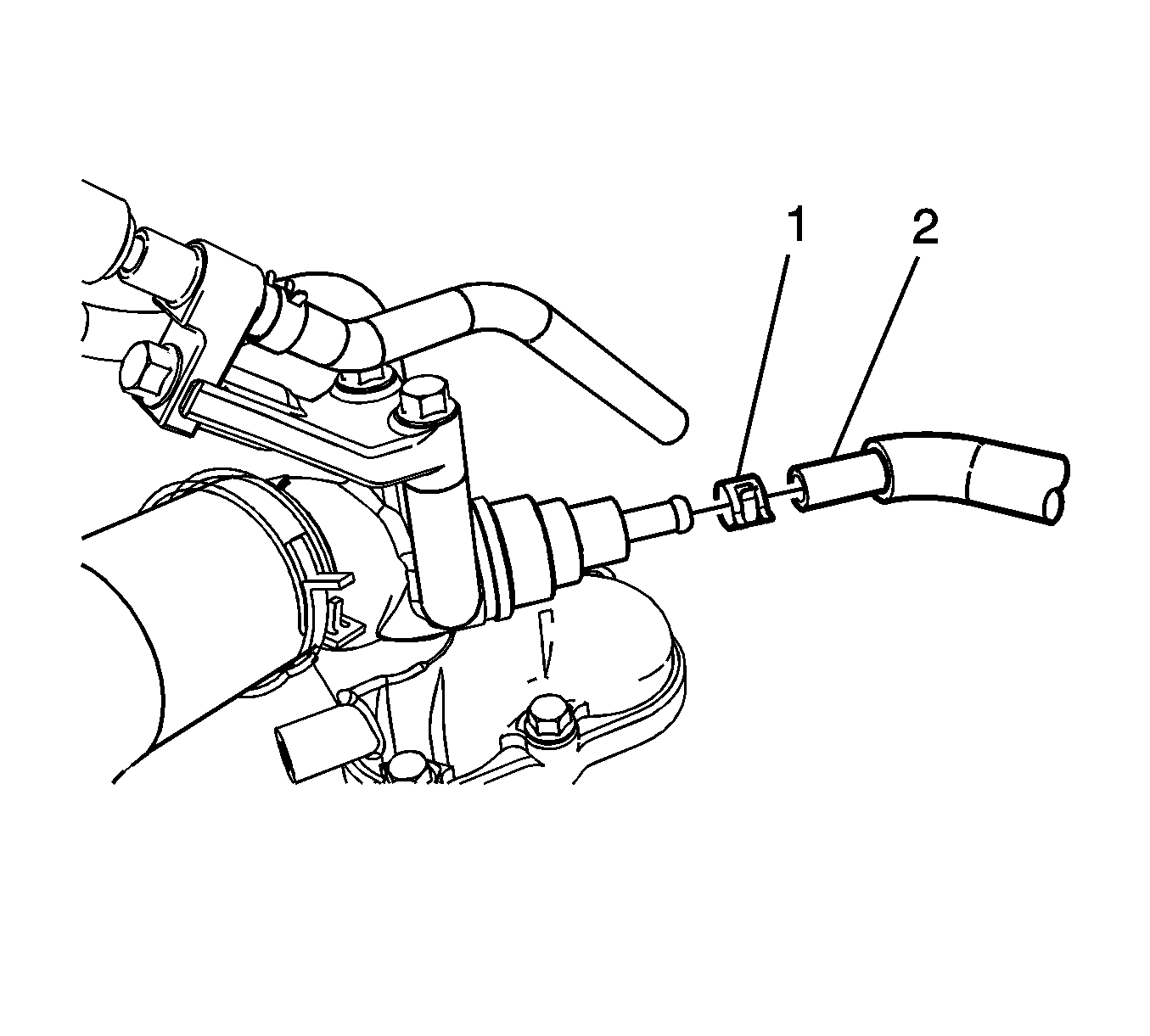
- Compress the clamp (1) and disconnect the turbocharger inlet cooling hose/pipe (2) from the thermostat housing.
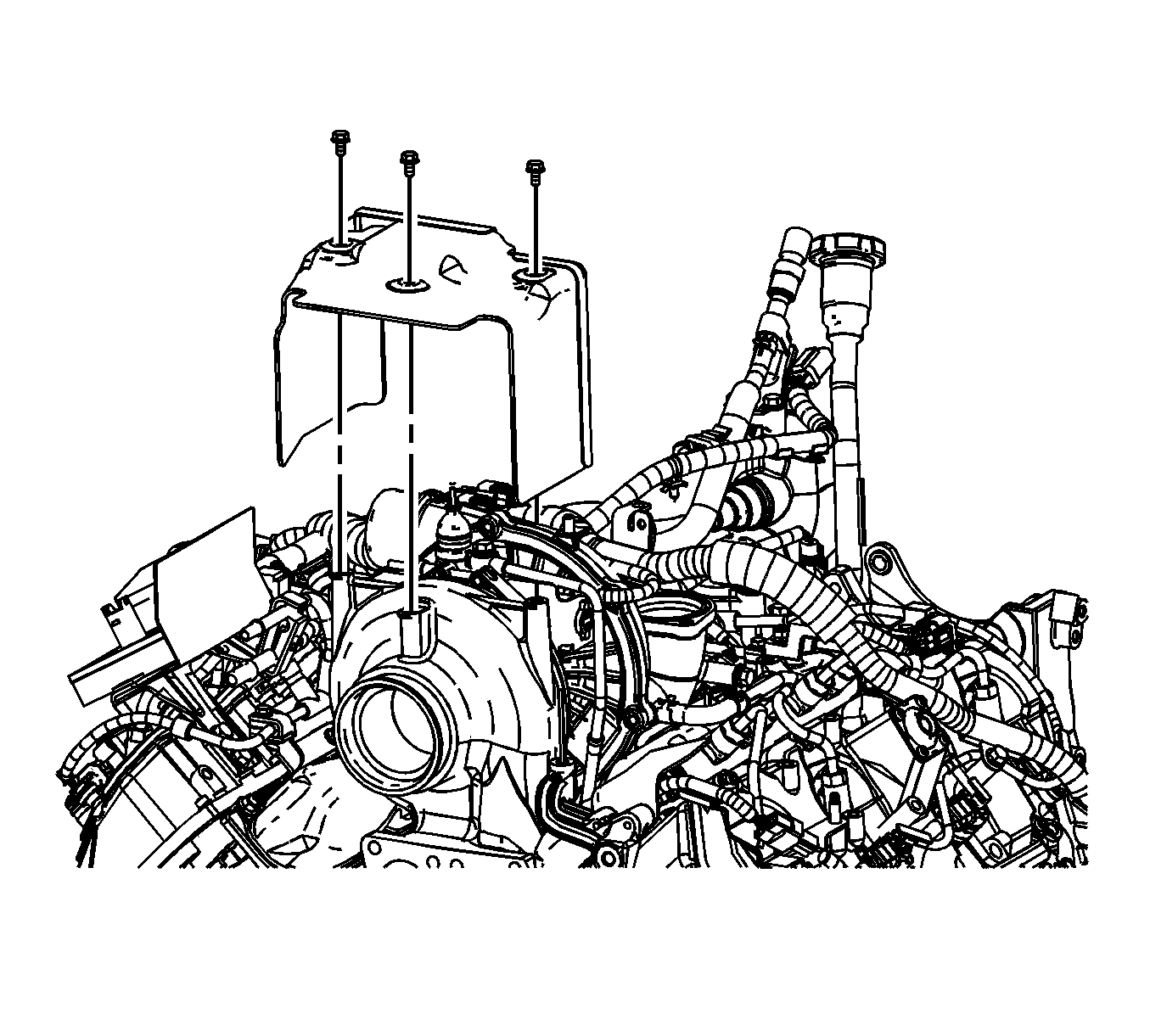
- Remove the 3 bolts and the turbocharger heat shield.
- Remove the left bank fuel return line bracket bolt (1) and the 2 glow plug module bracket bolts (2).
- Remove the left bank fuel line bracket bolt.
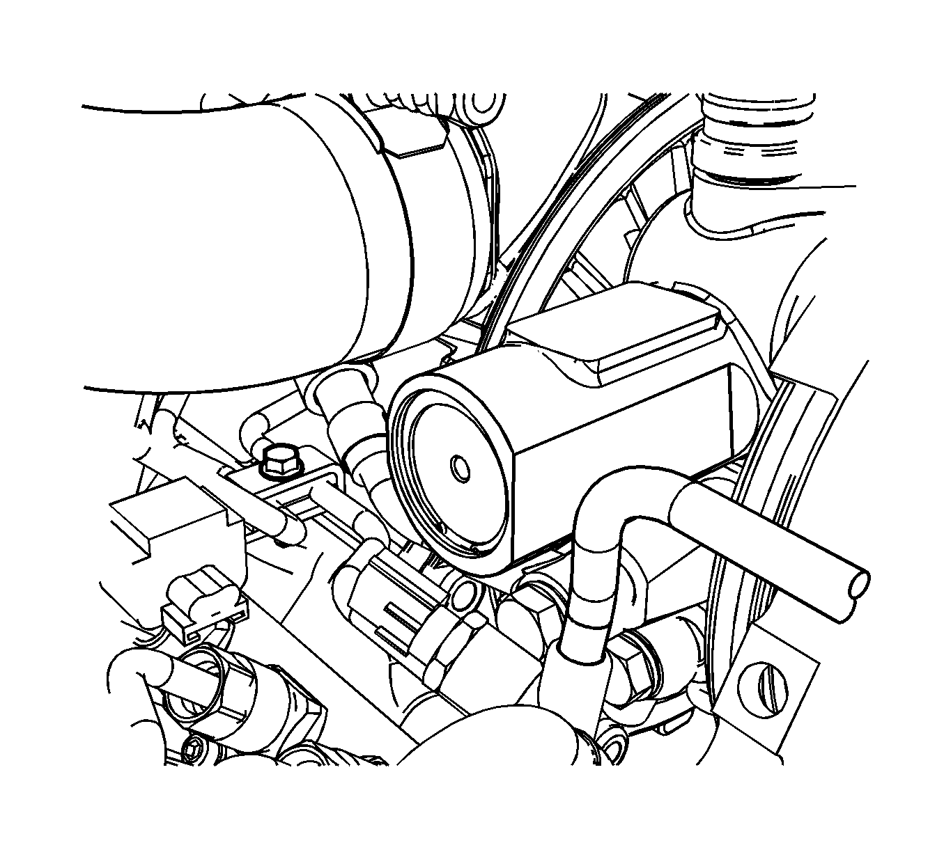
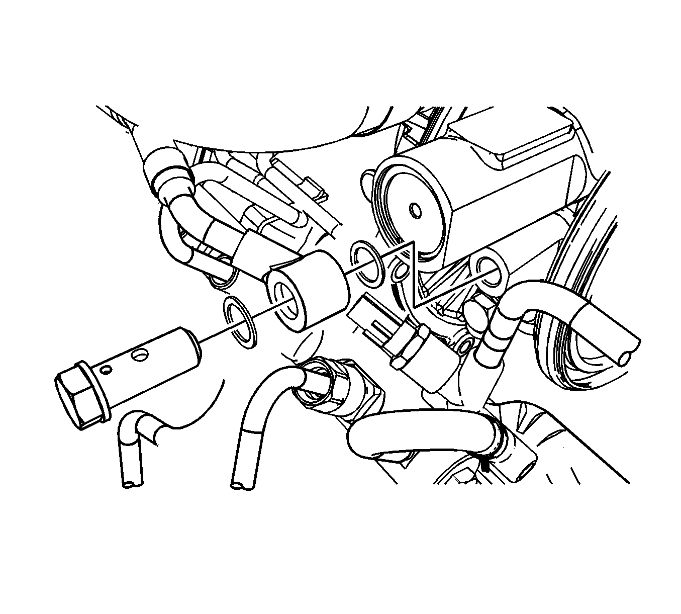
- Remove the turbocharger inlet cooling hose/pipe bolt and remove the inlet hose/pipe.
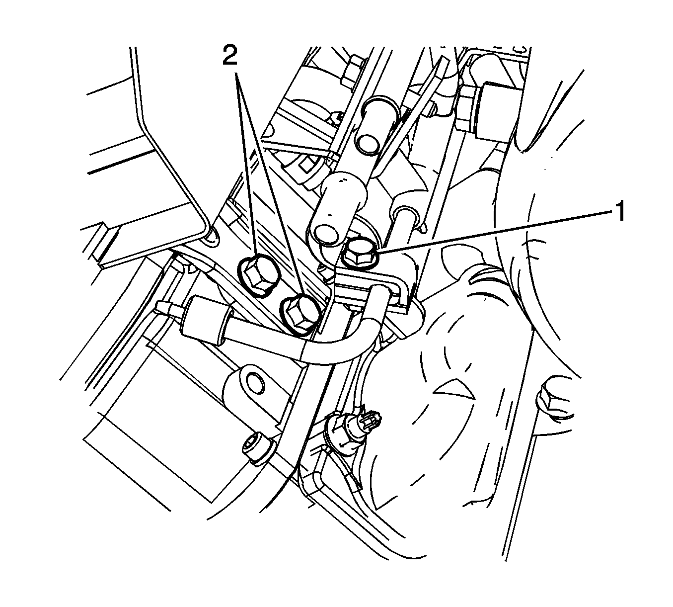
Important: Steps 6 and 7 are to allow for movement of the fuel lines and glow plug bracket to gain access to the turbocharger inlet cooling hose/pipe bolt.
Installation Procedure
- Position the turbocharger inlet cooling hose/pipe to the vehicle.
- Using new brass seals, install the turbocharger inlet cooling hose/pipe.
- Position the left bank fuel line and install the bracket bolt.
- Position the glow module bracket to the valve cover, install the 2 bolts (2) and the remaining left bank fuel line bracket bolt (1).
- Install the turbocharger heat shield and the 3 bolts.
- Position the turbocharger inlet cooling hose/pipe (2) to the thermostat housing and position the compression clamp (1) to secure.
- Fill the cooling system. Refer to Cooling System Draining and Filling.
- Install the engine cover. Refer to Engine Cover Replacement.
- Install the air cleaner outlet duct. Refer to Air Cleaner Outlet Duct Replacement.
Notice: Refer to Fastener Notice in the Preface section.

Tighten
Tighten the turbocharger inlet cooling hose/pipe bolt to 25 N·m (18 lb ft).

Tighten
Tighten the fuel line bolt to 25 N·m (18 lb ft).

Tighten
| • | Tighten the glow plug module bracket bolts to 10 N·m (89 lb in). |
| • | Tighten the fuel line bracket bolt to 25 N·m (18 lb ft). |

Tighten
Tighten the turbocharger heat shield bolts to 10 N·m (89 lb in).

Turbocharger Coolant Hoses/Pipes Replacement Outlet - LLY, LBZ
Removal Procedure
- Remove the engine cover. Refer to Engine Cover Replacement.
- Remove the 3 bolts and the turbocharger heat shield.
- Remove the exhaust gas recirculation (EGR) valve. Refer to Exhaust Gas Recirculation Valve Replacement.
- Remove the EGR cooler tube replacement. Refer to Exhaust Gas Recirculation Valve Cooler Replacement.
- Remove the center intake manifold. Refer to Center Intake Manifold Replacement.
- Remove the thermostat housing crossover. Refer to Thermostat Housing Crossover Replacement.
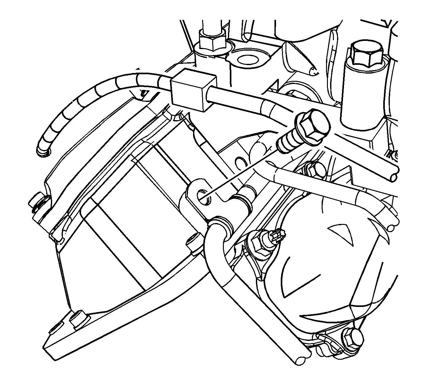
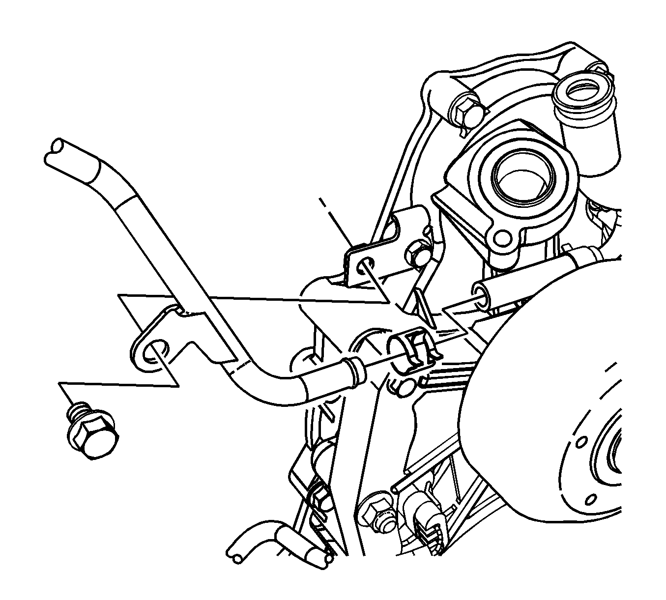
- Remove the turbocharger outlet cooling hose/pipe bolt from the valve cover.
- Remove the turbocharger outlet cooling hose/pipe bolt.
- Compress the clamp and disconnect the turbocharger cooling hose/pipe from the thermostat bypass pipe.
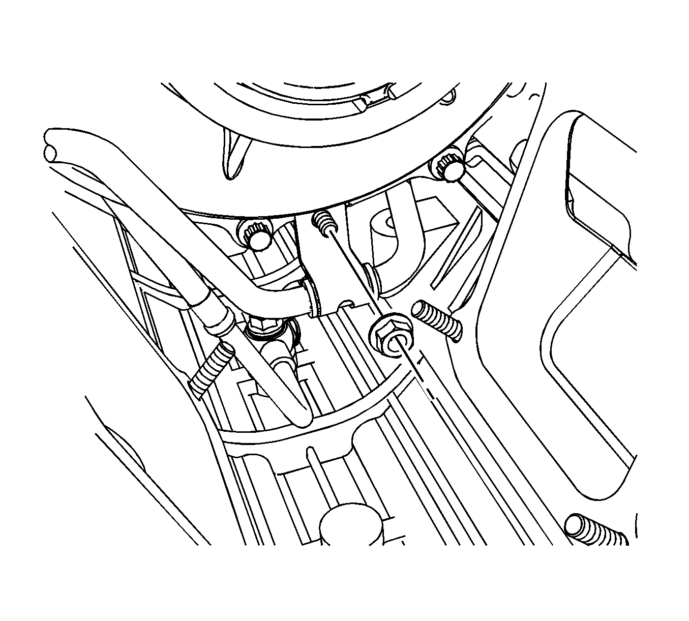
- Remove the turbocharger outlet cooler pipe to turbocharger nut.
- Remove the left bank fuel return line bracket bolt (1) and the two glow plug module bracket bolts (2).
- Remove the left bank fuel line bracket bolt.
- Remove the turbocharger outlet cooling hose/pipe to turbocharger bolt and remove the inlet hose/pipe.


Important: Steps 11 and 12 are to allow movement of the fuel lines and glow plug bracket to gain access to the turbocharger inlet cooling hose/pipe bolt.

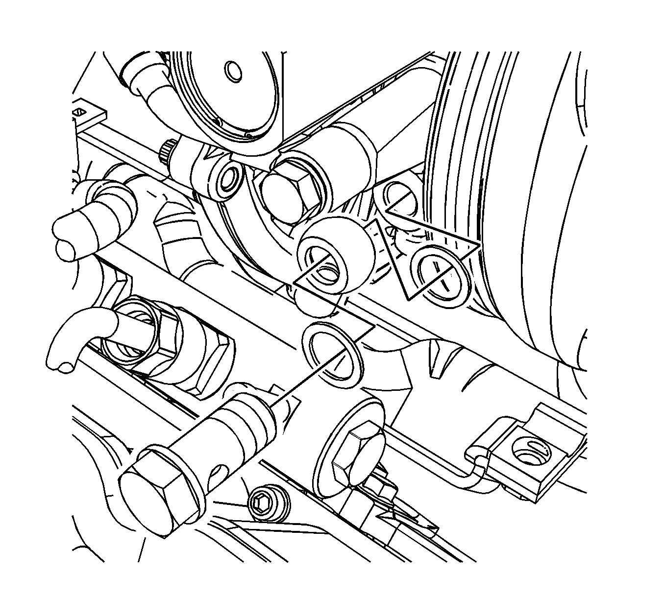
Installation Procedure
- Position the turbocharger inlet cooling hose/pipe to the vehicle.
- Using new brass seals, install the turbocharger inlet cooling hose/pipe bolt.
- Position the left bank fuel line and install the bracket bolt.
- Position the glow module bracket to the valve cover, install the two bolts (2) and the remaining left bank fuel line bracket bolt (1).
- Tighten the glow plug module bracket bolts to 10 N·m (89 lb in).
- Tighten the fuel line bracket bolt to 25 N·m (18 lb ft).
- Install the turbocharger heat shield and the 3 bolts.
- Install the turbocharger outlet cooler pipe to the turbocharger nut.
- Compress the clamp and connect the turbocharger cooling hose/pipe to the thermostat bypass pipe.
- Install the turbocharger outlet cooling hose/pipe to the valve cover.
- Install the turbocharger outlet cooling hose/pipe bolt.
- Install the thermostat housing crossover . Refer to Thermostat Housing Crossover Replacement.
- Install the center intake manifold. Refer to Center Intake Manifold Replacement.
- Install the EGR cooler tube replacement. Refer to Exhaust Gas Recirculation Valve Cooler Replacement.
- Install the EGR valve. Refer to Exhaust Gas Recirculation Valve Replacement.
- Install the engine cover. Refer to Engine Cover Replacement.
Notice: Refer to Fastener Notice in the Preface section.

Tighten
Tighten the turbocharger inlet cooling hose/pipe bolt to 25 N·m (18 lb ft).

Tighten
Tighten the fuel line bracket bolt to 25 N·m (18 lb ft).

Tighten

Tighten
Tighten the turbocharger heat shield bolts to 10 N·m (89 lb in).

Tighten
Tighten the turbocharger outlet pipe nut to 9 N·m (80 lb in).


Tighten
Tighten the turbocharger outlet pipe bolt to 9 N·m (80 lb in).
Tighten
Tighten the turbocharger outlet cooling hose/pipe bolt to 9 N·m (80 lb in).
