Inspection Procedure
Perform the following before disassembling the axle:
- Remove the fill plug from the axle.
- Remove the drain plug from the axle.
- Drain the axle lubricant.
- Inspect the oil and the case for metal chips.
Determine the source of the metal chips, such as a broken gear or bearing cage.
- Measure the rotating torque of the drive pinion and differential case assembly using an inch-pound torque wrench, if possible. Record the measurement.
- Check the drive pinion to ring gear backlash, if possible.
This information can be used in order to determine the cause of the axle problem. The information will also help when setting up and preloading the differential case.
Determine the cause of the axle problem before disassembly, if possible.
Disassembly Procedure
Tools Required
| • | J 45232
Differential Bearing Adjuster Needle Bearing Installer - LH |
| • | J 45228
Pinion Bearing Cup Remover/Installer |
| • | J 45234
Pinion Remover - 7.25 in Axle |
| • | J 45850
Front Axle Bushing Remover/Installer |
| • | J 8092
Universal Driver Handle - ¾ in - 10 |
- Remove the inner housing to differential carrier assembly bolts.
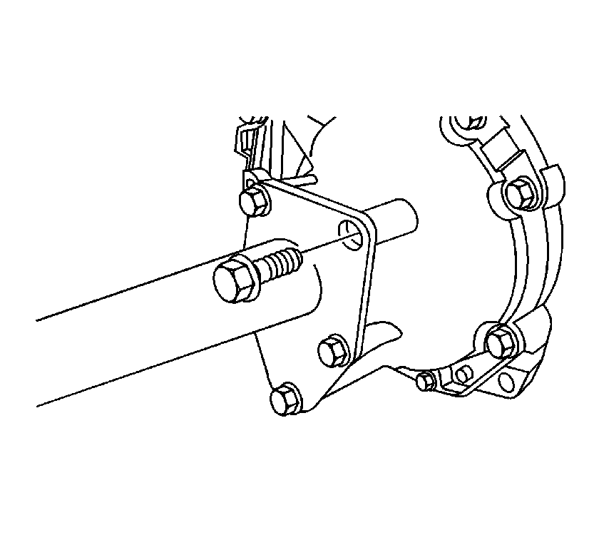
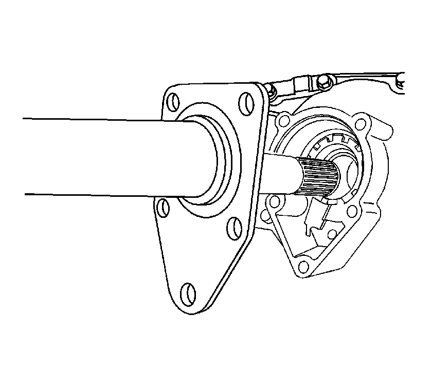
- Remove the inner housing and inner shaft from the differential
carrier assembly.
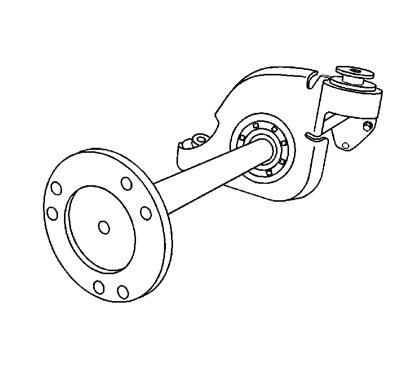
- Remove the inner shaft.
- Install the inner shaft housing into a vise.
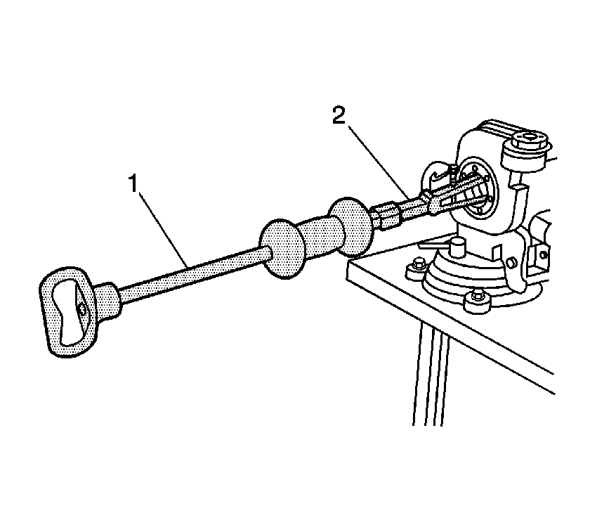
- Install the
J 29369-1
(2)
and the
J 2619-01
(1) behind the inner shaft bearing.
- Remove the inner shaft bearing and inner shaft seal using the
J 2619-01
.
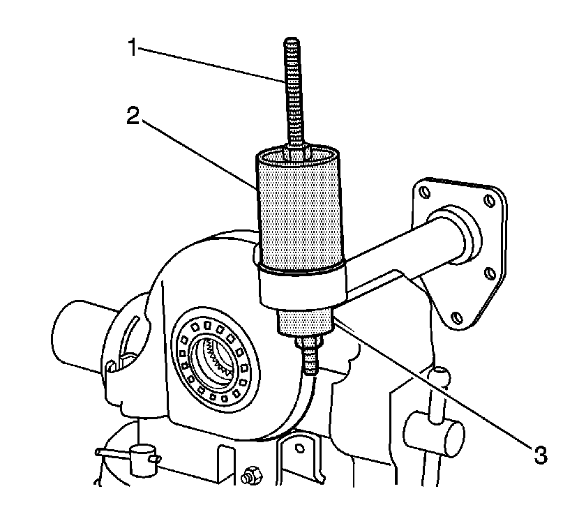
- Install the J 45850-2 (2), J 45850-3 (1), the forcing
screw, bearing, washers and nuts (1) over the upper inner shaft housing bushing as shown.
- Remove the upper inner shaft housing bushing using the
J 45850
.
- Remove the inner shaft housing from the vise.
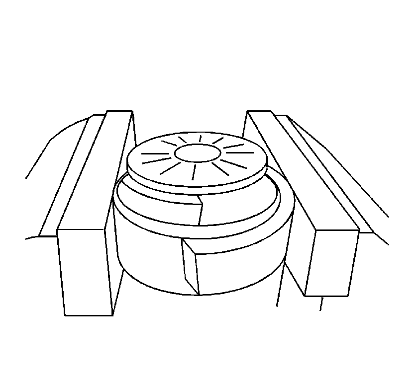
- Install the inner shaft housing into a vise so that the lower inner shaft bushing
bore is flush with the jaws of the vise.
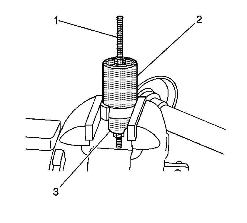
- Install the J 45850-2 (2), J 45850-3 (1), the forcing
screw, bearing, washers and nuts (1) over the lower inner shaft housing bushing as shown.
- Remove the lower inner shaft housing bushing using the
J 45850
.
- Remove the inner shaft housing from the vise.
- Install the differential carrier assembly into a vise.
Clamp only on the mounting flange of the differential carrier assembly case.
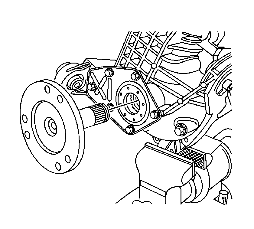
- Remove the left inner shaft using a hammer and a brass drift.
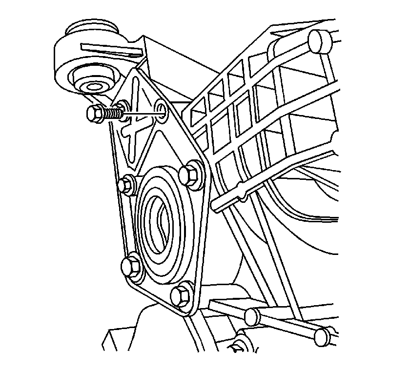
- Remove the inner shaft seal cover bolts.
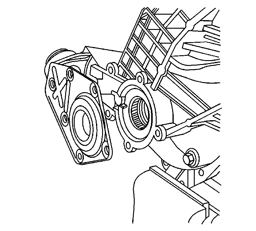
- Remove the inner shaft seal cover.
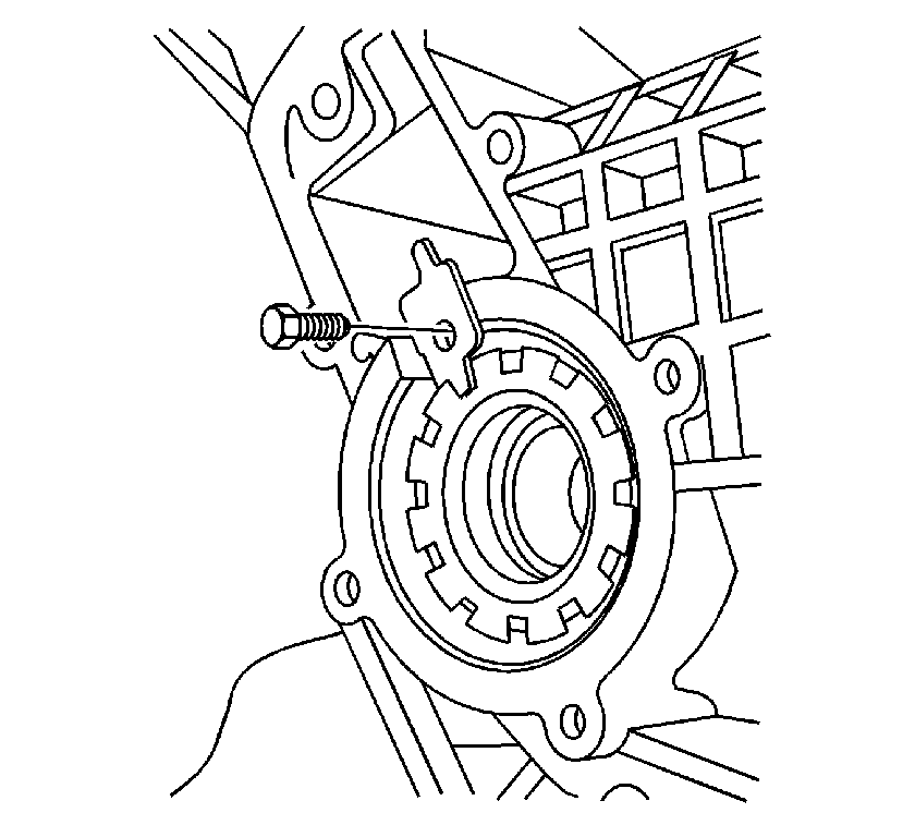
- Remove the left side differential bearing adjuster lock bolt.
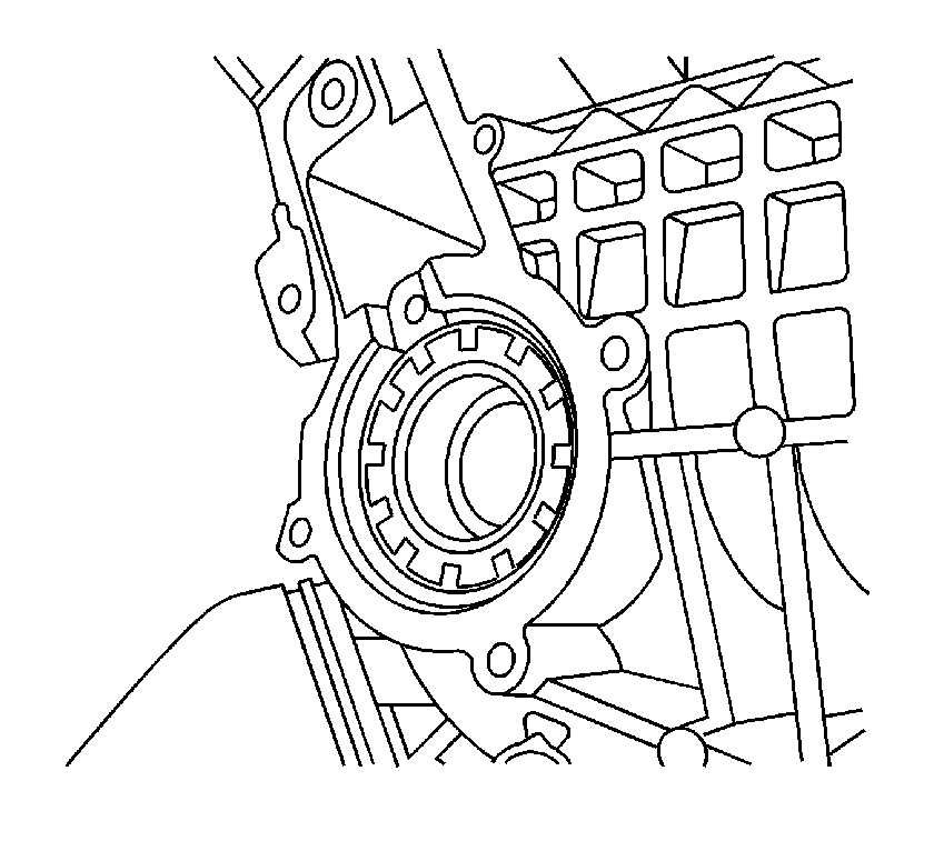
- Remove the left side differential bearing adjuster lock.
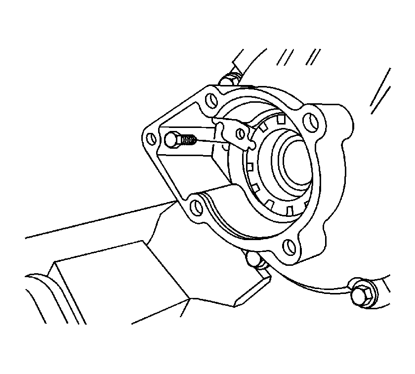
- Remove the right side differential bearing adjuster lock bolt.
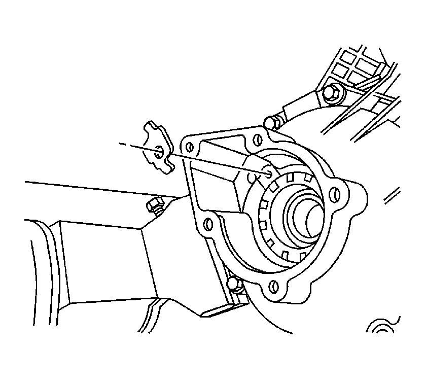
- Remove the right side differential bearing adjuster lock.
- Remove the differential carrier assembly from the vise.
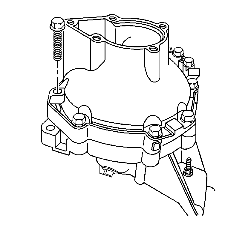
- Remove the differential carrier assembly bolts.
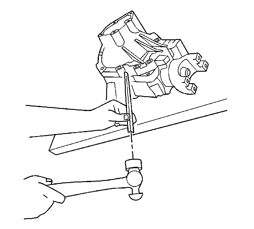
- Separate the right carrier case half from the left carrier case half by tapping on the carrier case using a
hammer and a brass drift.
- Remove the differential case assembly.
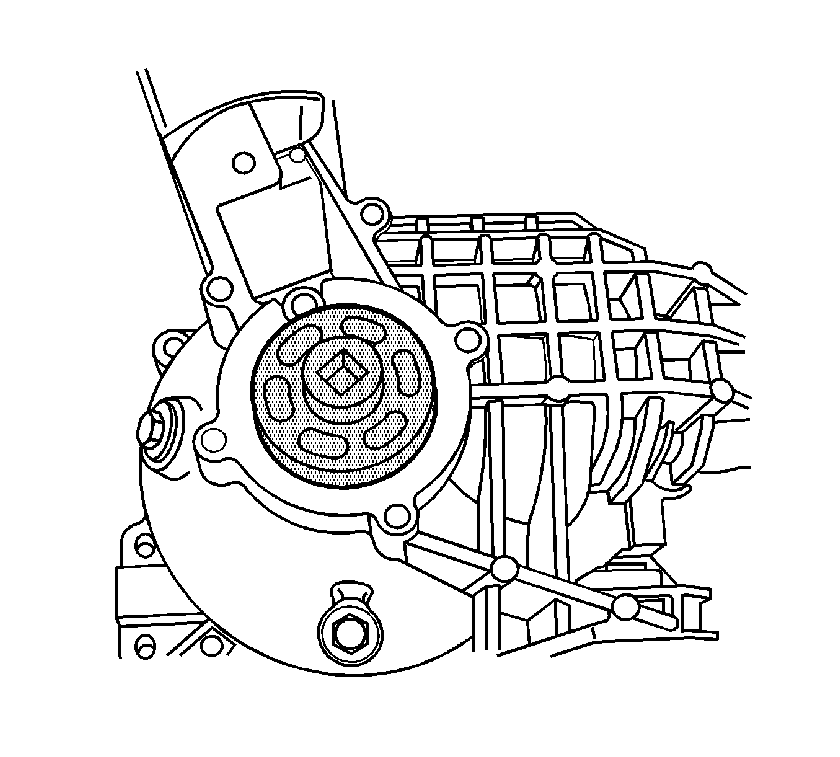
- Remove the left differential bearing adjuster by doing the following:
| 26.1. | Install the
J 45224
onto the differential bearing adjuster. |
| 26.2. | Turn the
J 45224
counterclockwise in order to remove the differential bearing adjuster. |
- Remove the differential bearing cup.
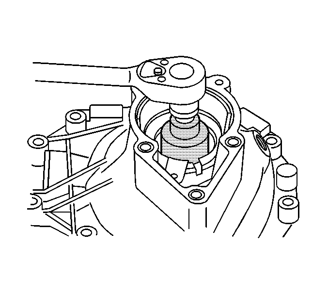
- Remove the right differential bearing
adjuster by doing the following:
| 28.1. | Install the
J 45224
onto the differential bearing adjuster. |
| 28.2. | Turn the
J 45224
counterclockwise in order to remove the differential bearing adjuster. |
- Remove the differential bearing cup.
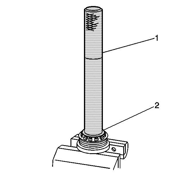
- Remove the left inner shaft bearing using the
J 45232
(2)
and the
J 8092
(1).
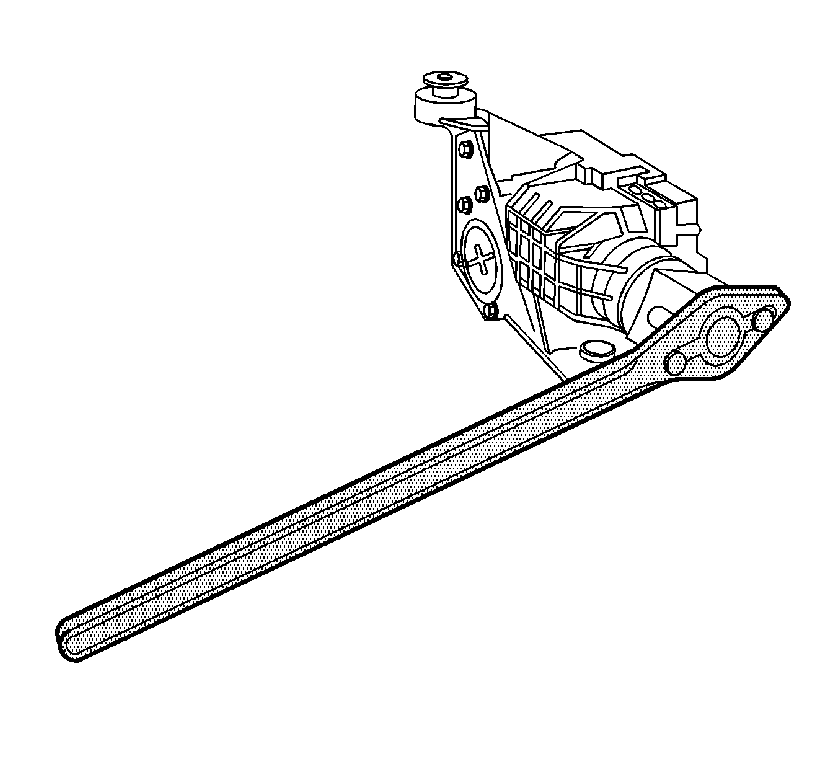
- Install the
J 8614-01
onto
the pinion yoke as shown.
Remove the pinion nut while holding the
J 8614-01
.
- Remove the washer.
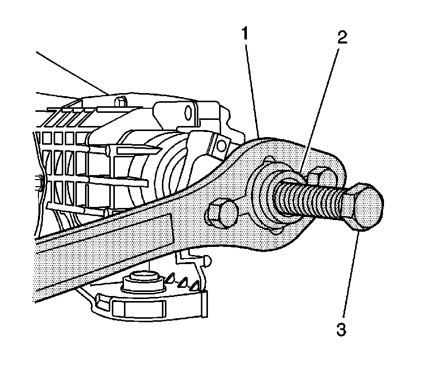
- Install the J 8614-2 (2) and the J 8614-3 (3)
into the
J 8614-01
(1) as shown.
- Remove the pinion yoke by turning the J 8614-3 (3) clockwise while holding the
J 8614-01
(1).
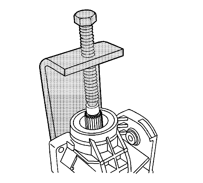
- Install the
J 45234
onto the left differential carrier
case and over the drive pinion as shown.
- Remove the drive pinion by turning the forcing screw of the
J 45234
clockwise.
- Remove the pinion oil seal using a suitable seal removal tool.
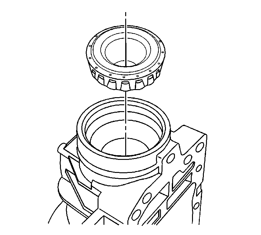
- Remove the outer pinion bearing.
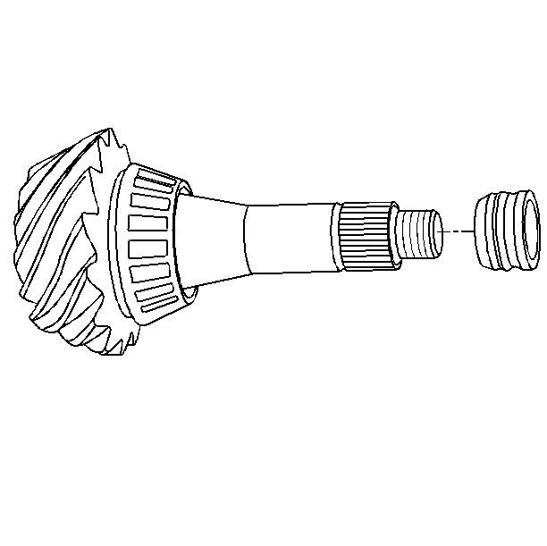
- Remove the collapsible spacer from the pinion.
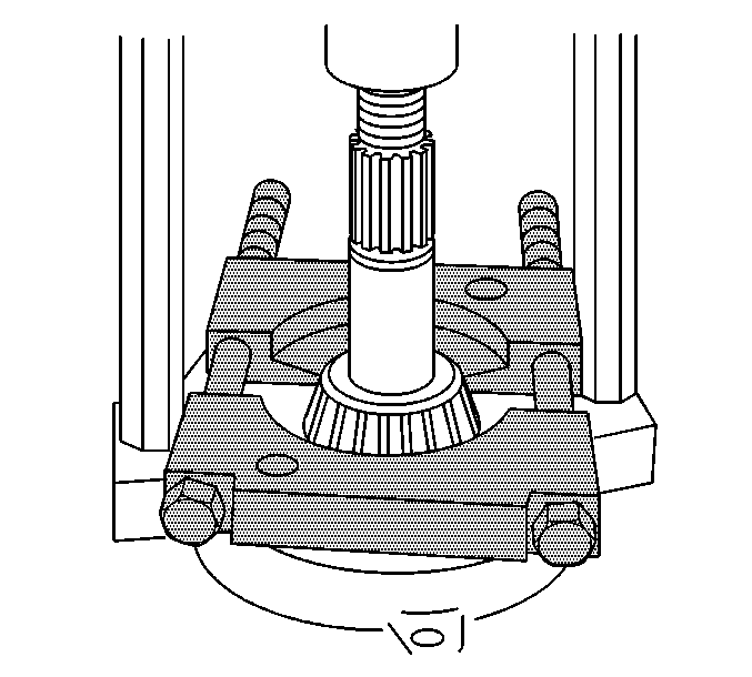
- Remove the inner pinion bearing by installing the
J 22912-B
between the pinion bearing and the pinion gear and pressing the bearing off the pinion.
- Remove the pinion gear selectable shim.
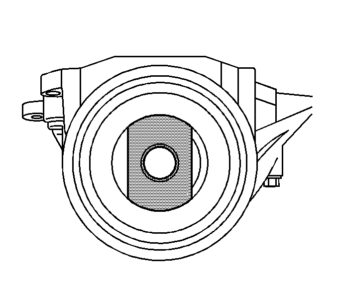
- Install the J 45228-4 to the outer pinion bearing cup as shown.
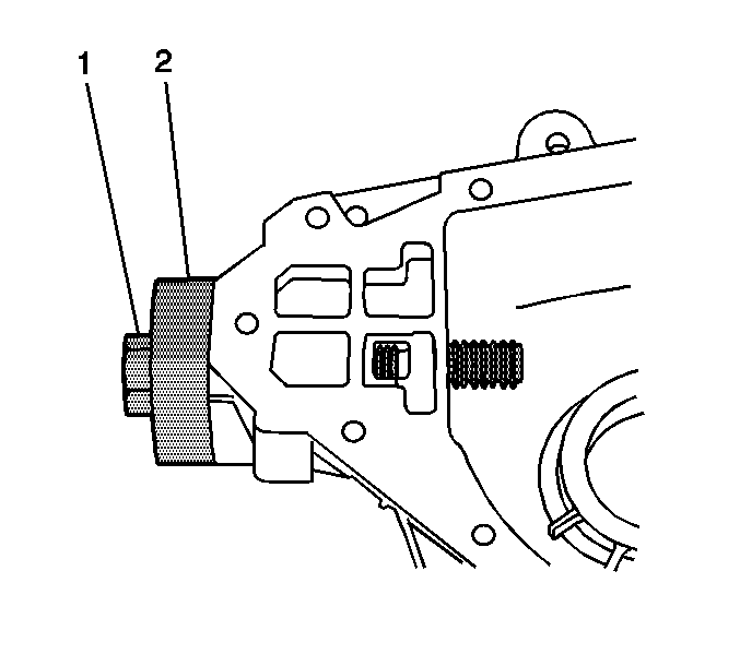
- Install the J 45228-1 (2) and the J 45228-5 (1) to the J 45228-4.
Seat the ridge of the J 45228-1 (2) into the outer pinion bearing cup bore.
- Remove the outer pinion bearing cup by turning the J 45228-5 (1) clockwise.
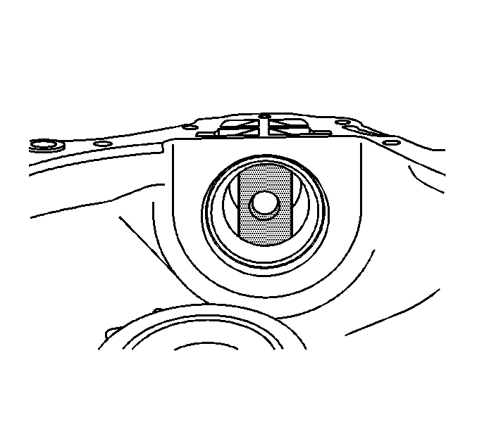
- Install the J 45228-4 to the inner pinion bearing cup as shown.
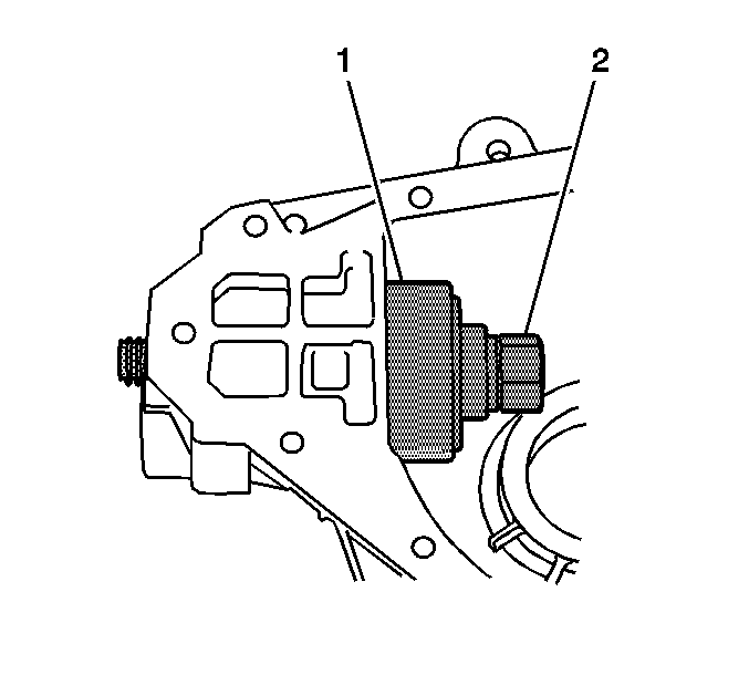
- Install the J 45228-1 (1) and the J 45228-5 (2) to the J 45228-4.
- Remove the outer pinion bearing cup by turning the J 45228-5 (2) clockwise.
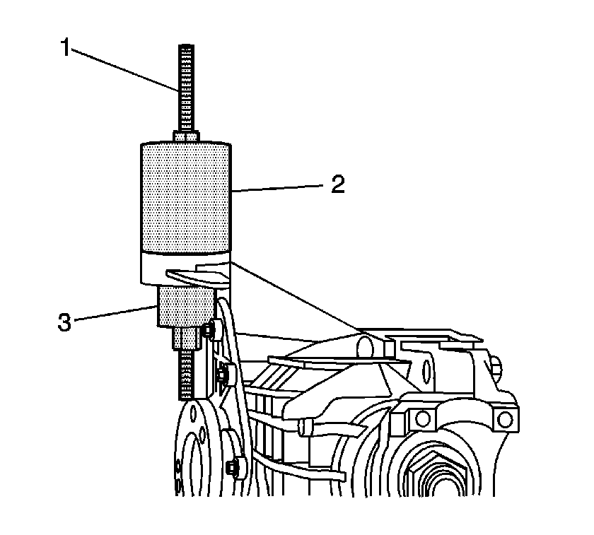
- Remove the upper differential carrier assembly bushing by performing the following
steps:
| 48.1. | Install the J 45850-2 (2), the J 45850-3 (3), the forcing screw, the thrust bearing, the washers, and the nuts (1) over the differential carrier assembly bushing as shown. |
| 48.2. | Remove the upper differential carrier assembly bushing by holding the lower nut and tightening the upper nut of the
J 45850
. |
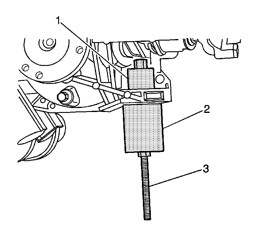
- Remove the lower differential carrier assembly bushing by performing the following
steps:
| 49.1. | Install the J 45850-2 (2), the J 45850-3 (1), the forcing screw, the thrust bearing, and the nuts (3) over the differential carrier assembly bushing as shown. |
| 49.2. | Remove the lower differential carrier assembly bushing by holding the upper nut and tightening the lower nut of the
J 45850
. |


