For 1990-2009 cars only
Tools Required
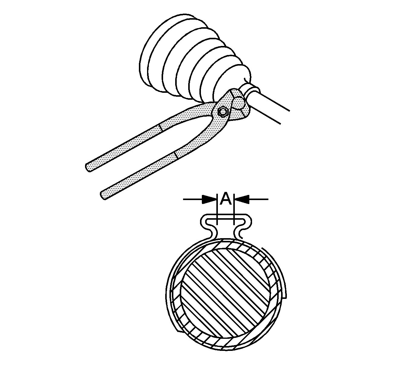
J 43218 Clamp Pliers - Narrow Jaw
Removal Procedure
- Remove the wheel drive shaft. Refer to Wheel Drive Shaft Replacement .
- Wrap a shop towel around the axle shaft.
- Place the wheel drive shaft horizontally in the bench vise.
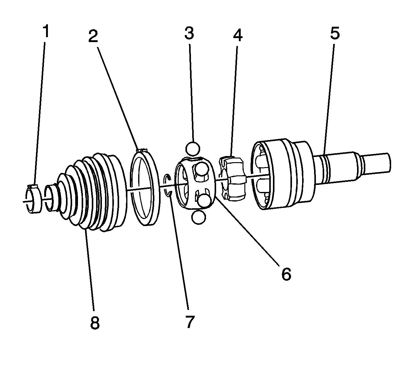
- Remove the large seal clamp (2) and the small seal clamp (1). Use a side cutter or other suitable tool and discard the clamp.
- Separate the seal (8) from the joint (5) outer race at the large end.
- Position the seal behind the joint face.
- Wipe the grease from the face of the joint inner race, cage, balls, etc.
- Remove the outer joint from the wheel drive shaft bar.
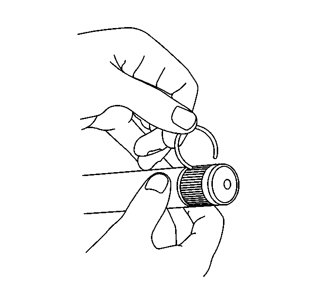
- Remove the retaining ring from the wheel drive shaft bar.
- Remove the seal from the wheel drive shaft bar.
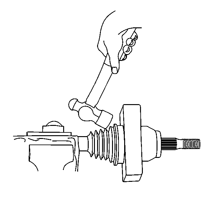

| 8.1. | Have an assistant hold the joint housing. |
| 8.2. | Position a wood block between the seal and the joint (along the joint face). |
| 8.3. | Strike the wood block with a hammer to compress the axle shaft retaining ring. |
| 8.4. | Continue to strike the wood block to remove the outer joint from the wheel drive shaft bar. |
Installation Procedure
- Install the large clamp (2) and the small clamp (1) onto the seal (8).
- Install the seal onto the wheel drive shaft bar.
- Install the retaining ring onto the wheel drive shaft bar.
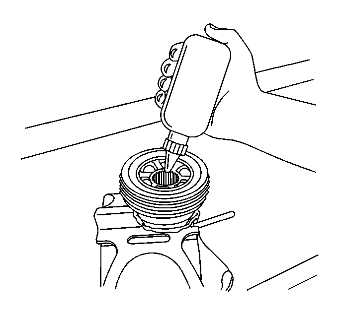
- Insert the grease from the service kit into the outer joint.
- Position the outer joint horizontally.
- Engage the inner race splines onto the axle shaft splines.
- Compress the axle shaft retaining ring.
- Install the outer joint to the wheel drive shaft bar.
- Position the small end of the seal (8) over the mating groove in the wheel drive shaft bar.
- Compress the small clamp using the J 43218 or equivalent, until dimension (A) is 0.5-1.6 mm (0.02-0.06 in).
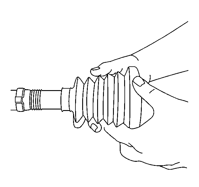
- Vent the joint to relieve excess trapped air.
- Compress the large clamp using the J 43218 or equivalent, until dimension (A) is 0.5-1.6 mm (0.02-0.06 in).
- Install the wheel drive shaft. Refer to Wheel Drive Shaft Replacement .


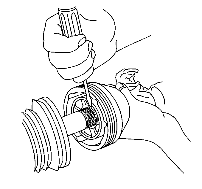
| 7.1. | Press one end of the retaining ring, using a flat-bladed screwdriver or equivalent tool, into the wheel drive shaft bar groove while firmly pressing the outer joint onto the axle shaft. |
| 7.2. | Continue to work around the retaining ring until it is compressed. |
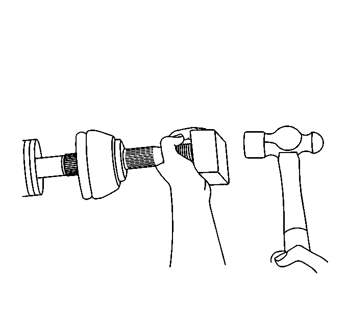
| 8.1. | Position a wood block squarely over the end of the outer joint threaded shaft. |
| 8.2. | Use a hammer to drive the outer joint onto the bar. |
| 8.3. | Continue to drive the outer joint until you feel the outer joint seat fully onto the wheel drive shaft bar. |
| 8.4. | Inspect to be sure that the axle shaft and the inner race stepped surfaces are fully seated to each other. |

